6
General Information
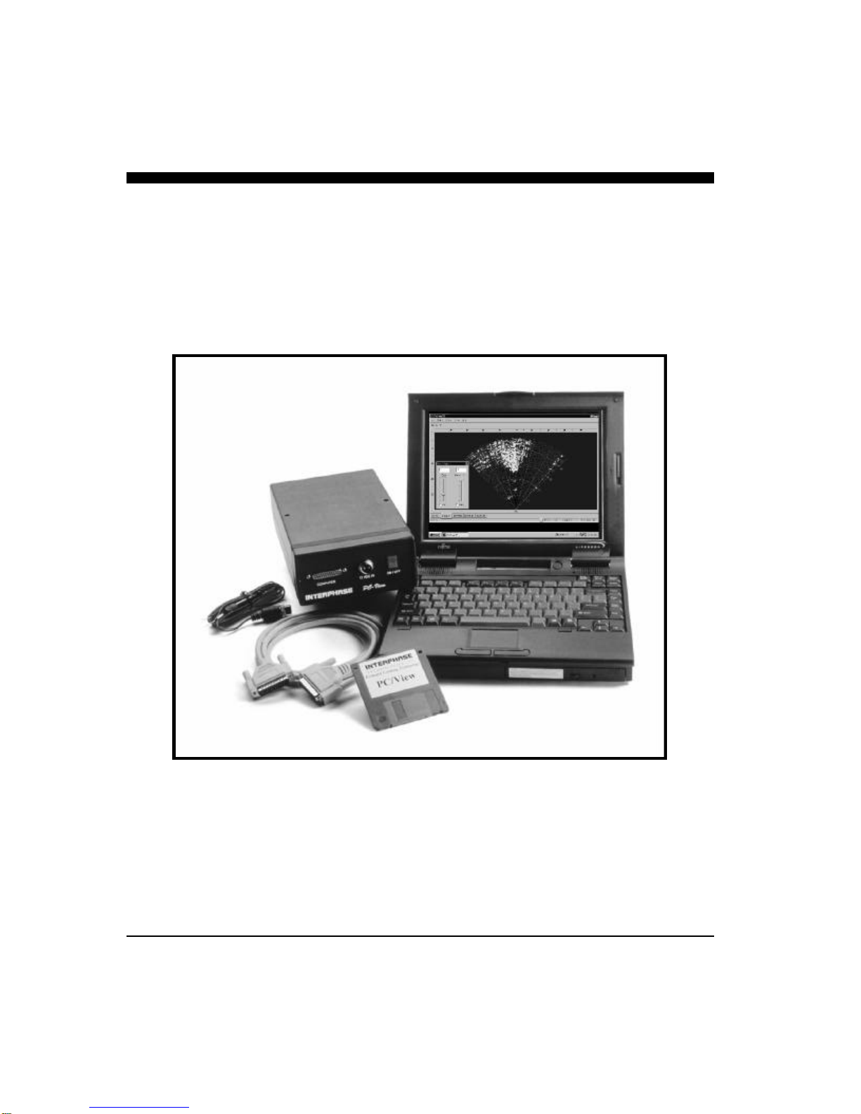
Thank you for choosing the Interphase PC/View
Dual-Axis Forward Scanning Sonar. The PC/View
has been designed to work with your on-board PC
and will display water depth, bottom conditions, fish
and other submerged objects and debris, all on your
computer’s high resolution color display. If you al-
ready have an Interphase scanning transducer in-
stalled on your vessel, you can order a PC/View
without a transducer (see page 50).
To insure that you receive the maximum benefits
available from the outstanding features of the Inter-
phase PC/View, this manual includes a detailed
guide to the use and interpretation of the system’s
modes and displays. An instructive demonstration
mode has been designed into the PC/View to famil-
iarize you with the unit’s features. In addition, the
Quick Start chapter gives you the necessary informa-
tion to get your system up and running as quickly as
possible. Please read the Installation chapter care-
fully before attempting to install PC/View on your
vessel.
Warranty Information
Interphase provides a Limited Warranty on the PC/
View Forward Scanning Sonar. Please read this
warranty (reprinted at the back of this manual) and
closely follow its terms and conditions should your
PC/View require repair. It is highly recommended
that you save all packing materials so that, in the
unlikely event that you must return your PC/View for
repair, it can be fully protected.
Should you experience a problem with your PC/
View, first refer to the Troubleshooting section (Page
48) of this manual. Most common problems and
their solutions are described here. If problems per-
NAVIGATION WARNING
Nautical navigation is a critical element in
the safety and success of each open-water
boating experience and should only be
performed by experienced navigators.
While the PC/View product is a useful
navigation aid, it should never be relied
upon as the only means of navigation. It is
prudent to use more than one proven
instrument and more than one accepted
method in support of navigation decisions.
1 Introduction
Award Winning
Technology
For its pioneering work in developing
Phased Array Scanning Sonar,
Interphase Technologies won the
prestigious IMTEC INNOVATION
AWARD.
The PC/View Forward Looking
Scanning Sonar is based on this same
award-winning technology.