Interphase PC/180 User manual

INTERPHASEINTERPHASE
PC/180™
OPERATION
MANUAL

2
To Our Customer:
Thank you for choosing the Interphase PC/180 Forward Scanning Sonar. Throughout
the development of this fine product, we have been primarily concerned with creating a
unit that offers the best possible value for your money. Selection of features, ease of use,
superior performance and outstanding reliability were the benchmarks upon which all
important design decisions were made. We are proud of the PC/180 Forward Scanning
Sonar and your satisfaction is very important to us. We welcome any comments or
suggestions that you might have about this equipment.
It is very important that you complete and return the WARRANTY REGISTRATION
CARD within 15 days of purchase so that your unit may be protected under the warranty.
Thank You Again,
INTERPHASE TECHNOLOGIES, INC.
©1999 Interphase Technologies, Inc.
Interphase PC/View™ and PC/180™ are trademarks of Interphase Technologies, Inc.
Other brands or products are the trademarks or registered trademarks of their respective holders and
should be treated as such.
Publication # = PC/180 1.0 990531 (P/N 25-1050-000)

3
1Introduction 6
General Information 6
Warranty Information 6
Unpacking and Inspection 7
2Installing PC/180 8
Transducer Installation 9
The Transducers 9
Forward Direction 10
Selecting the Best Location 10
Using the Fairing Blocks 11
Thru-hull Mounting 12
Acoustic Interface Module Installation 14
Software Installation 16
3Quick Start 18
Running PC/180 18
Defaults 18
Demo Mode 19
Beam Width 19
4Basic Operation 20
Getting Started 20
The Toolbar 20
The Status Bar 21
Operating Modes 21
Demo Mode 21
Real-Time Mode 21
Setting System Parameters 22
Parallel Port Address 22
Transducer Mount Corrections 22
Level Adjustment 22
Align Adjustment 23
Keel Offset 23
Contents

4
Displays 24
Setting Color and Units 24
VERT: Vertical Scan Display 26
HORZ180: Horizontal Scan Display 26
DOWN: Downlooker Display 26
VSPLIT: Vertical Split-Screen Display 27
HSPLIT180: Horizontal Split-Screen Display 27
Depth Window 28
Adjusting the Gain and Range 28
Gain Adjustment 28
Range Adjustment 29
Using the Alarm 30
Adjusting the Viewing Area 30
Sector Width and Steer 30
Scan Mode and Method 31
Vertical Scan 31
Horizontal Scan 32
Zoom 32
Adjusting the Depth Tracker 33
Surface Masking 33
Threshold 33
Saving Data with Screen Capture 35
5Advanced Operation 36
Working with NMEA Navigation 36
Logging Depth 37
Using PC/180 Diagnostics 39
6Interpreting Displays 40
Principles 40
Interpreting the Vertical Display 40
Forward Imaging Capabilities 40
Transducer Sidelobe Effects 41
Interpreting the Horizontal Display 42
Imaging the Bottom 42
Special Situations 43
Forward Imaging Capabilities 43

5
7Reference 44
Theory of Operation 44
Sonar Basics 44
Phased Array Technology 45
Maintenance 47
Troubleshooting Guide 48
Interference Problems 49
Specifications 50
How To Obtain Service 51
Index 52
Warranty 55

6
General Information
Thank you for choosing the Interphase PC/180
Dual-Axis Forward Scanning Sonar. The PC/180
has been designed to work with your on-board PC
and will display water depth, bottom conditions, fish
and other submerged objects and debris, all on your
computer’s high resolution color display.
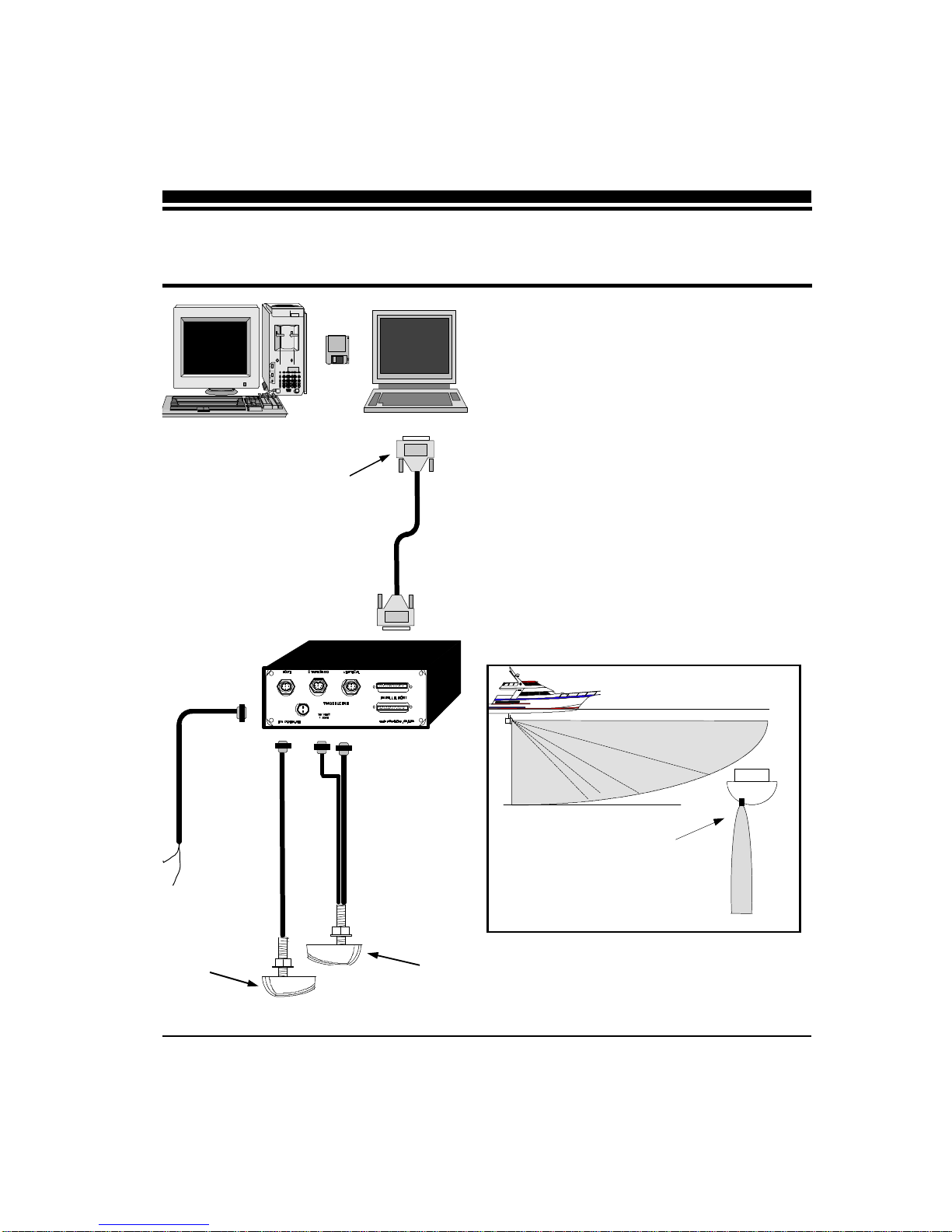
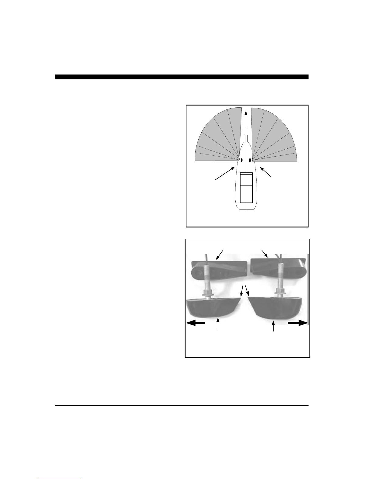
The PC/180 combines a 90-degree vertical scanning
sector with a horizontal scanning sector that covers
the full 180 degrees in front of your vessel. PC/
180’s two-transducer configuration has the added
advantage of avoiding any potential acoustic shadow-
ing created by a deep keel. This is because the port
half of the horizontal scan is accomplished using a
transducer mounted on the port side of the keel while
the starboard half of the horizontal scan is accom-
plished using a transducer mounted on the starboard
side of the keel.
To insure that you receive the maximum benefits
available from the outstanding features of the Inter-
phase PC/180, this manual includes a detailed guide
to the use and interpretation of the system’s modes
and displays. An instructive demonstration mode has
been designed into the PC/180 to familiarize you
with the unit’s features. In addition, the Quick Start
chapter gives you the necessary information to get
PC/180 software up and running as quickly as possi-
ble. Please read the Installation chapter carefully
before attempting to install PC/180 on your vessel.
Warranty Information
Interphase provides a Limited Warranty on the PC/
180 Forward Scanning Sonar. Please read this war-
ranty (reprinted at the back of this manual) and
closely follow its terms and conditions should your
PC/180 require repair. It is highly recommended
NAVIGATION WARNING
Nautical navigation is a critical element in
the safety and success of each open-water
boating experience and should only be
performed by experienced navigators.
While the PC/180 product is a useful
navigation aid, it should never be relied
upon as the only means of navigation. It is
prudent to use more than one proven
instrument and more than one accepted
method in support of navigation decisions.
1 Introduction
Award Winning
Technology
For its pioneering work in developing
Phased Array Scanning Sonar,
Interphase Technologies won the
prestigious IMTEC INNOVATION
AWARD.
The PC/180 Forward Looking
Scanning Sonar is based on this same
award-winning technology.

7
that you save all packing materials so that, in the un-
likely event that you must return your PC/180 for re-
pair, it can be fully protected.
Should you experience a problem with your PC/180,
first refer to the Troubleshooting section (p. 48) of this
manual. Most common problems and their solutions
are described here. If problems persist, call Inter-
phase Technical Service at (831) 477-4944. We will
be happy to assist you, and if required, we will give
you instructions on how to quickly get your unit re-
paired.
The enclosed warranty registration card must be com-
pleted and returned to Interphase within 15 days of
purchase so that your unit may be protected under the
warranty. Failure to return the warranty card may
cause unnecessary delays in processing your unit for
warranty repair.
Unpacking and Inspection
When unpacking your PC/180, the following items
should be found in the package. Please notify your
Interphase dealer immediately if any items are missing.
Standard Equipment
Description Part Number
Acoustic Interface Module X1-VIEW-180
Parallel Cable, 10’ length 04-1035-000
12VDC Power Supply Cable 04-0001-008
PC/180 Software Diskettes(2) 52-1003-001
PC/180 Operation Manual 25-1050-000
Transcucers:
200 kHz Horizontal/Vertical Scan
(starboard) T1-0200-034
200 kHz Horizontal Scan (port) T1-0200-033
IMPORTANT NOTICE
Please fill out and return the Warranty
Registration Card immediately. This is our
only method of contacting you should new
features and enhancements become
available for your PC/180.
During the first year of your warranty, any
software upgrades will be free of charge,
and after the warranty period has expired,
software upgrades will be available for a
nominal charge.
Acoustic Interface
Module
PC/180 Software
12 VDC Power Cable
10’ Long Parallel Cable

8
Intsallation of the PC/180 can be divided into three
separate tasks, described in three sections in this
chapter:
1) Location and Installation of the Transducers
2) Installation of the Acoustic Interface Module
3) Installation of the PC/180 Software.
The schematic diagram at left shows a typical instal-
lation of the PC/180 using an on-board desktop or
laptop PC.
2 Installing PC/180
Vertical Scan Pattern
Scan pattern
viewed from
the bow
To Computer’s
Parallel Port
12 VDC
PORT Trans-
ducer with ONE
cable. (HORZ) STBD Transducer with
TWO cables. (HORZ
AND VERT)
Acoustic Interface Module

9
Transducer Installation
The PC/180 uses three 8-element phased transducer
arrays (a total of 24 elements) configured in two sep-
arate through-the-hull (thru-hull) transducers. The
port side transducer includes a single horizontally
scanning array and the starboard side transducer in-
cludes a horizontally scanning array and a vertically
scanning array. The arrays are “potted” in a smooth-
surfaced plastic material that is acoustically transpar-
ent. DO NOT allow any solvents (i.e. gasoline,
acetone) to come in contact with the transducers
as this may dissolve the plastic housing.
Proper performance of your PC/180 is very depen-
dent on a good transducer installation and normally,
thru-hull installations are performed by a profes-
sional in a boat haul-out facility. We strongly sug-
gest you seek professional assistance before attempt-
ing to mount these thru-hull transducers.
The Transducers
The two PC/180 transducers are designed to be
mounted on opposite sides of the vessel’s keel. Al-
though similar in appearance, the two transducers
operate differently and it is important that they be
mounted on the proper side of the vessel’s keel.
Mount the Port-Side transducer on the port side of
the keel (the left side of the hull, looking forward
from the stern), and mount the Starboard-Side
transducer on the starboard side of the keel (the right
side of the hull, looking forward from the stern).
The Port and Starboard transducers can be identified,
as shown in the diagram at right, by the fact that the
Starboard-side transducer is slightly larger and has
two cables compared to the Port-side transducer’s
single cable. In addition, each cable has a small la-
bel approx. 6” from the connector which identifies it
as the PORT HORZ, STBD HORZ or STBD VERT.
(Horz stands for Horizontal direction and Vert stands
for vertical direction.)
Port-Side
Transducer Starboard-Side
Transducer
180 Degree Horizontal Scan Pattern
Vessel
Starboard Side
Transducer with
TWO 33’ cables.
Port Side
Transducer with
ONE 33’ cable.
Aft Ends
Fairing Blocks

10
Forward Direction
The orientation of the mounted transducers is critical
to the performance of the PC/180. Note that the
more blunt, rounded end of each transducer should
be pointed forward. The angled, more narrow ends
should be pointed aft as shown in the figure at left.
Selecting the Best Location
The best location to mount the thru-hull transducer
will vary with the type of boat. In order to simplify
the installation, attempt to find a location with a
small dead-rise angle.
a. On displacement hulls (sailboats, trawlers, etc.)
locate the transducer about 1/3 aft along the wa-
terline. Generally this provides the best compro-
mise between obtaining aeration-free water and
minimizing propeller noise. Water near the bow
and near the keel can be quite aerated. Since the
PC/180’s transducer can not see through aerated
water, it is best to mount the transducer midway
between these two areas.
b. On planing powerboat hulls, the transducer
should be mounted well aft and close to the keel
to insure that the transducer is in contact with the
water at higher boat speeds. Unfortunately,
mounting the transducers well aft limits the max-
imum forward range in front of the vessel’s bow.
However, the transducers must be in the water to
work and if they are mounted too far forward on a
planing hull they will often lose contact with the
water. In this situation, the PC/180 can only be
used at slower vessel speeds which do not result
in planing operation.
DO NOT install a bronze transducer housing di-
rectly into an aluminum or steel hull because elec-
trolytic corrosion will occur.
Transducer cables will need to be routed to the
Acoustic Interface Module. If you need transducer
cable lengths greater than the standard 30’ length,
order three 30’ extension cables (Interphase Part #
04-0014-008).
FORWARD
Fairing Block
Transducer
Typical Thru-Hull Transducer Locations
Full Keel Sailboat
Displacement Power
Vessel Hull
L = Length of Waterline
~ 1/4 to 1/3 L
L = Length of Waterline
~ 1/4 to 1/3 L
Transducer
Transducers

11
Using the Fairing Blocks
Nearly all vessels have some dead-rise angle at the
transducer mounting location. If the thru-hull trans-
ducers were mounted directly to the hull, the sound
beam from the transducer would be tilted off the ver-
tical at the same angle as the dead-rise and would
cause errors in the interpretation of the displayed
picture. To correct this situation, most thru-hull
installations will require the use of fairing blocks to
insure that the transducer is mounted in the proper
orientation..
Two custom-molded fairing blocks for the PC/180
transducers have been included with your system to
make installation as simple as possible.
Measure the dead-rise angle of the hull at the se-
lected mounting location and cut the block to a shape
that fits the exact contour of the hull. After cutting
the fairing block, trial-fit the block to the hull. The
upper part of the block should be inside the hull and
the lower part of the block should be outside the hull
to clamp the assembly in place as shown in the dia-
gram at right.
It is very important that the flat top surface of the
transducer be parallel to the water. Because of the
equipment and skill required, we suggest that your
professional boatyard cut the fairing blocks and in-
stall the transducers.
One of two trans-
ducer fairing blocks
included with your
PC/180 system.
Threaded
Bronze Stem
Boat’s Hull
Fairing Block
(bottom)
Transducer Body
Fairing Block
(top)

12
Thru-hull Mounting
Take the following steps to mount each thru-hull
transducer:
1) Drill a 1/8” pilot hole from inside the hull to
assure access to tighten the housing nut and
clearance for the transducer cables. If there is
any hull irregularity near the selected mount-
ing location, it may be desirable to drill from
the outside.
2) Use a 1” hole saw and drill the hole from the
outside of the hull. Sand or clean the area
around the hole, inside and outside to insure
that the sealing compound will adhere prop-
erly to the hull. Select a marine grade bed-
ding/caulking compound and use according to
the instructions.
3) Remove the bronze hex nut from the housing
and cables.
4) Uncoil the two transducer cables and thread
them through the hole to the inside of the hull.
Apply a 1/8” thick layer of sealant on the up-
per flat surface of the bronze housing and fair-
ing block (if used).
5) From the outside of the hull, push the cables
and housing into the 1” hole. Twist the hous-
ing slightly to squeeze out excess sealant.
Carefully confirm that the transducer is
aligned so that the blunt rounded end (the
front) is pointed directly toward the front
of the boat.
**WARNING**
Do not cut or splice your phased-array
transducer cables or remove the 9-pin
connectors. Doing so will seriously
degrade the performance of your PC/180
and VOID YOUR WARRANTY.
Tools Required for Transducer
Installation:
♦ Variable speed electric drill with a chuck
capacity of 10 mm (3/8”) or larger.
♦ Hole saw or spade bit 19 mm (7/8”) for
transom hole to route cable and connector
♦ Chamfer bit or 6 mm (1/4”) drill bit
♦ Drill bit No. 28 or 4 mm (9/64”)
♦ Drill bit 3 mm (7/64”)
♦ Marine bedding/sealing compound
Note: Make sure your tooling is sharp and of
the correct diameter before proceeding.
WARNING
DO NOT apply tension to the transducer
cables as this may sever internal connections.

13
6) Install and tighten bronze hex nut (allow for
swelling in wooden hulls). Do not over-tighten
nut.
7) Remove excess sealant from the outside to as-
sure smooth water flow over the transducer.
8) Route the cables back to the PC/180 Acoustic
Interface Box. If possible, avoid running the
cables alongside of antenna cables or other sen-
sitive wiring.
If you need longer transducer cable lengths,
purchase the optional 30’ extension cables
(Interphase Part #04-0014-008). Three exten-
sion cables will be required.
WARNING
Wood hulls will expand after the boat is put
back into the water, so it is important that, if
you have a wood hull, the transducer be only
hand-tightened until the wood fully expands.
Otherwise the wood fairing block may crack.
WARNING
Be sure to check for leaks when the boat is
placed in the water. Allow at least 24 hours
after installation for any leak to appear.
IMPORTANT NOTE
If the boat is kept in saltwater it is
recommended that the transducer be coated
with an anti-fouling paint. USE ONLY
WATER BASED ANTI-FOULING PAINT.
DO NOT USE KETONE-BASED PAINTS.
Ketone-based anti-fouling paint will attack the
plastic materials used in the transducer.
Completed Installation
View From Front of Vessel Looking Aft.
Vessel’s Hull

14
Acoustic Interface
Module Installation
The black box that came with your PC/180 is called
the Acoustic Interface Module. It houses the trans-
mitters and receivers that communicate with the
transducers. The Acoustic Interface Module must be
connected to the parallel port of the on-board com-
puter, to the transducers and to a source of 12 VDC
power.
1) Select a location to mount the Acoustic Interface
Module. Keep in mind that the unit must be
protected from from moisture and extreme tem-
peratures. Also, you will need to route the 10’
computer parallel cable, the power cord and
transducer cables to the location that you
choose.
2) Connect the two-pin plug on the end of the
power supply cable to the power supply jack on
the back panel of the Acoustic Interface Module.
To minimize electrical interference, carefully
route the power cable so that it does not run
parallel to, or close to the transducer cable, en-
gine, refrigeration, bilge pump or any other criti-
cal wiring.
Connect the red wire to the positive terminal
and the black wire to the negative terminal of
your boat’s 12 VDC battery.
3) Connect one end of the parallel cable to the con-
nector labeled PARALLEL PORT on the back
panel of the Acoustic Interface Unit. Connect
the other end of the parallel cable to the parallel
port on your computer.
WARNING
Signals transmitted through adjacent cables
can interfere with one another. Thus, it is
advisable, where possible, to route sensitive
cables and antennas so that they do not run
adjacent to or parallel to one another.
PORT STARBOARD VERTICAL
PARALLEL PORT
12 VDC
1 AMP
P/N X1-VIEW-180 made in Santa Cruz, CA, USA
Power Supply Jack
Transducer Connectors
Parallel Ports
(use either one)
Acoustic Interface Module
Back Panel

15
4) Connect the three transducer cables to the
matching ports on the back panel of the Acous-
tic Interface Module:
Cable label Panel label
PORT HORZ PORT
STBD HORZ STARBOARD
STBD VERT VERTICAL

16
Software Installation
The PC/180 software includes a group of program
files and a demonstration data set. These files will
all be automatically copied to your computer’s hard
disk during installation.
The total size of the PC/180 installation is about 3
MegaBytes. We recommend that you make sure that
there is at least 10 MegaBytes of free space on your
hard drive before you begin the installation. If you
plan to save screen-captured images, you will need
additional space. We recommend beginning with a
minimum of 20 MegaBytes of free space.
PC/180 will run only on a computer with Microsoft
Windows 95, 98 or NT. This is because PC/180 is a
32-bit program which uses true multi-tasking and,
thus, requires a 32-bit operating system.
Take the following steps to install PC/180 on your
Windows 95, 98 or NT computer:
1) Exit all programs that are currently running.
2) Insert the PC/180 Disk 1 into your computer’s A
drive (or B drive).
3) From the Start Bar, select Run. Browse to find
Setup.exe on the A: (or B:) drive or type A:\setup
(or B:\setup). Click on the OK button to begin
the installation.
4) Follow the Setup instructions in each dialog box
that is displayed. Click the Next button to ac-
cept the defaults.
The second dialog box will prompt you to accept
the default destination folder for the PC/180
files or select a different folder. The default
destination folder is:
C:/Program Files/Interphase/Pc180
The third dialog box will prompt you to select a
destination for the PC/180 icon in your Win-
dows Start Bar.
NOTE
PC/180 is not available in a DOS version.
If you are not running Windows 95, 98 or
NT on your computer but instead are using
Windows 3.1 or a version of DOS (6.0 or
greater), you need PC/View for DOS. PC/
View requires a different transducer set
which scans 90 degrees in the horizontal
direction.
PC/180’s Operating Software is located
on the two 3.5” diskettes that are in-
cluded with your system.
INTERPHASE
PC/180™
Operating Software
Disk 1

17
5) When you are prompted by the Setup program,
as shown below, remove Disk 1 from your
floppy drive and insert Disk 2.
6) The Setup program will prompt you to restart
your computer after it has completed the instal-
lation. You do not have to restart your computer
immediately but you must restart it before you
can run PC/180.

18
Running PC/180
To start the PC/180 system, turn the Acoustic Inter-
face Module power switch ON. Then run PC/180 by
clicking on the Windows Start Bar. Select Programs
and PCView, then click on the PCView icon. Alter-
natively you can click on the Windows Start Bar,
select Run... and type in the path and name of the
PC/180 program (C:\Program
Files\Interphase\Pc180\Pc180.exe).
Each time you run PC/180, you will be prompted to
agree with the Warranty Terms and acknowledge
that you have read the Navigation Warning. After
you have read this agreement once, the appearance of
the box will serve as a reminder of the limitations of
navigation aids. Use the scroll bar to move through
the text then click on the I Agree button to run PC/
180.
If all components have been installed and all cables
are connected, and the Acoustic Interface Module is
on, PC/180 will immediately begin to collect and
display data. Take the following steps to adjust PC/
180 for basic operation:
1) Set defaults as described below. Be sure that
Auto Gain and Auto Range are off.
2) Select a display (see p.24).
3) Select a range setting that is slightly greater
than your current water depth (see p.29).
4) Adjust the gain by first turning it down until no
imagery is visible on the display. Increase the
gain until you begin to see noise, then decrease
the setting by one (see p.28).
Defaults
The default settings for many of the PC/180 features
are shown in the table at left. Hard defaults are al-
3 Quick Start
Parameter Menu Default Type
Auto-Screen Capture File Off Hard
Color Setup Normal Soft
Units Setup Feet Soft
Surface Masking Setup Off Hard
Depth Threshold Setup Normal Hard
Auto Gain Adjust Off Hard
Gain Adjust 32 Soft
Auto Range Adjust Off Hard
Range Adjust 25 Feet Soft
Alarm Adjust Off Hard
Sector Width Adjust 180 Degrees Soft
Sector Steer Adjust 90 Degrees Soft
Scan Mode Adjust Normal Soft
Scan Method Adjust Swept Soft
Zoom Adjust Off Soft

19
ways reset when you exit the program. Soft defaults
are recommended settings for general operation.
If you are running PC/180 for the first time, it will
start with the default settings as shown at left.
Change the settings by selecting the appropriate com-
mand from the specified menu.
Demo Mode
PC/180 includes a built-in Demo mode which will
display the stored data that was installed with the
software. Demo mode will automatically be started
if the Acoustic Interface Module is not on or it is
disconnected from the computer during start-up.
Running in DEMO mode will allow you to practice
and to get a feeling for the PC/180’s many features
before actually using the system in real situations on
the water.
Beam Width
The PC/180’s Beam Width is approximately 12 de-
grees in both the vertical and horizontal scan modes.
The diagrams at right and below show the approxi-
mate width of the vertical and horizontal scanning
beams at different distances from the boat. The PC/
180 will generally image features within the shaded
areas.
The PC/180 horizontal scan is oriented approxi-
mately ten degrees down from horizontal (see the
diagram below). Thus, the depth to the center of the
beam is approximately 18 percent of the distance
from the boat.
Width of Acoustic Beam
Vertical Scan
250
500
750
1000 210
158
105
53
Distance
Forward
or Below
Boat
PC/View can
see targets
within this
area.
12º Beam
Width
TIP
The width of the 12-degree main beam is
approximately 1/5 of the distance from the
boat
25 50 100
4.59
18
10 Degrees
7
29
Distance Forward 12º Beam
Width
Depth
Width of Acoustic Beam
Horizontal Scan
PC/View can
see targets
within this
area.

20
Getting Started
This chapter will help you to learn the modes of opera-
tion and the basic features of the PC/180 system. For
more experienced users, this chapter can be used as a
reference. Read Chapter 3 Quick Start to learn how to
start the PC/180 software.
PC/180 is a Windows application with a standard Win-
dows menu structure. The PC/180 screen includes a
data display window as well as the Toolbar and the
Status Bar.
The Toolbar and Status Bar can be toggled on or off
via the View Menu.
The Toolbar
The Toolbar enables quick access to features which are
used often including:
•Screen Capture, which saves the current screen to
the hard disk (see p.35),
•About PC/180, which displays the software ver-
sion number, and
•Alarm Reset, which turns off the depth alarm after
it has been triggered (see p.30).
The Toolbar also includes two digital data displays
including:
•Depth beneath the transducer calculated by PC/
180 with the current units, and
•Vessel Position information if it is available (e.g.
38º 58.95N 121º 58.49W; refer to the discussion
of NMEA navigation input in Chapter 5 Advanced
Operation).
The Status Bar
The Status Bar displays current information about PC/
180 operation including:
•Status Message,
•Ping Light, which alternates between red and
green on consecutive pings,
4 Basic Operation
Screen Capture Alarm Reset
Toolbar
About PC/View
Longitude
Latitude
Water Depth
Units
Vessel Position
Other manuals for PC/180
1
Table of contents
Other Interphase Sonar manuals

Interphase
Interphase Color Twinscope User manual

Interphase
Interphase Advantage User manual

Interphase
Interphase Sonar Engine SE-200 User manual

Interphase
Interphase iScan V90 User manual

Interphase
Interphase Color Twinscope User manual

Interphase
Interphase Outlook User manual

Interphase
Interphase Sea Scout User manual

Interphase
Interphase 180 User manual

Interphase
Interphase Spectra User manual

Interphase
Interphase Proble User manual