Intertec Data Systems EFD145DLFR000 Series Owner's manual

Contents
A. Duct Support Installation 3
B. Application Information 3
C. Door Operation 4
D. Installation Guidelines 5
Upow Furnace and Upow Air Handler Installation
5
Downow Air Handler Installation 5
Downow Furnace Installation 6
Side Return Furnace Installation 7
E. Electrical Connections 8
Electrical Connections to a COM Sys Air Handler in
Conventional 24 V Mode 10
Electrical Connections to a COM Sys Air Handler 11
Electrical Connections to a COM Sys Furnace
in 24 V Mode 12
Electrical Connections to a COM Sys Furnace 13
Electrical Connections to an Oil Furnace 14
Electrical Connections for Dual Whole House
Air Cleaners 15
F. Air Cleaner Operation 17
G. SET-UP Mode 17
Installer Set-Up Mode 17
Pre-Filter Setting 17
Cell Cleaning Setting 18
Field Charger Power Level 18
Field Charger Power Level Setting 18
H. Maintenance 18
Cleaning 18
I. Outline Drawings 23
J. Pressure Drop Information 26
Whole House Air Cleaner
ALL phases of this installation must comply with NATIONAL, STATE AND LOCAL CODES
IMPORTANT — This Document is customer property and is to remain with this unit.
Please return to service information pack upon completion of work.
Installation
Operation
Maintenance
Upow Furnace
Models
EFD145DLFR000**
EFD175DLFR000**
EFD210DLFR000**
EFD245DLFR000**
ssWARNING
!
This information is for use by individuals having adequate
backgrounds of electrical and mechanical experience.
Any attempt to repair a central air conditioning product
may result in personal injury and/or property damage.
The manufacturer or seller cannot be responsible for the
interpretation of this information, nor can it assume any
liability in connection with its use.
Downow Furnace
Models
EFD17DDLFR000**
EFD21DDLFR000**
Air Handler
Models
EFD175DLAH000**
EFD215DLAH000**
EFD235DLAH000**
EFD260DLAH000**
s
sWARNING
!
RISK OF ELECTRIC SHOCK: These servicing instructions
are for use by qualied personnel only. To reduce the risk
of electric shock, do not perform any servicing other than
that contained in these operating instructions unless you
are qualied to do so.
50 Hz Air Handler
Models
TFD215CLAH005E
TFD235CLAH005E
TFD260CLAH005E
18-HE122D1-1-EN

2 Numbers in [brackets] are for 50 Hz international systems. Pub. No. 18-HE122D1-1-EN
Installer’s Guide
Unpack the Air Cleaner and check to make sure all
components are included. They consist of:
1) PRE-FILTER - traps large particles such as hair
and lint before they can enter the cell section.
2) FIELD CHARGER - Charges the contaminants.
Only to be removed, cleaned or serviced by a quali-
ed technician.
3) COLLECTION CELL (2) - removes and collects
very small impurities from the air.
4) CABINET - mounts between the furnace/air han-
dler and return air ductwork and houses the COL-
LECTION CELLS, FIELD CHARGER and PRE-
FILTER.
5) POWER DOOR - the solid state power supply compo-
nents that convert the 24 Volt AC to the high-voltage,
direct current required to power the FIELD CHARGER
and COLLECTION CELLS. Allows access to the
Figure 1 Components of the Air Cleaner
COLLECTION CELLS, FIELD CHARGER and PRE-
FILTER.
6) TRANSFORMER - supplies 24 Volts to the indoor unit
and air cleaner (not included with 50 Hz units)
7) 24 VOLT POWER/CONTROL CABLE
8) GASKET, LITERATURE AND HARDWARE
PACKET
Check carefully for any shipping damage. This must
be reported to and claims made against the trans-
portation company immediately. Check to be sure all
major components are in the unit. Any missing parts
should be reported to your supplier at once, and
replaced with authorized parts only.
NOTE: International (50 Hz) Timings:
Due to dierences in electrical systems outside
the United States, customers with 50 Hz electrical
systems will need to be aware of minor dierences
in the timings shown in this guide. 50 Hz timings
will appear in [brackets] following the standard 60
hz timings.
The whole house air cleaner can be installed either as
part of a Communicating heating and air conditioning
system or as part of a traditional 24 volt system.
When installed as part of a Communicating System
in which the indoor unit, outdoor unit, and 900 series
comfort control are equipped with our exclusive
Communicating technology, this system performs a
continuous loop of system diagnostics and data output.
The Communicating System monitors itself and quickly
identies any operational faults, automatically issuing a
service alert if needed.
The whole house air cleaner can also be installed as
part of a traditional 24 volt heating and air conditioning
system.
ཱི
ི
ུ
ི
ཱ
ཱུ
ྲྀཷ
ཱི

Pub. No. 18-HE122D1-1-EN Numbers in [brackets] are for 50 Hz international systems. 3
Installer’s Guide
Step 1: Review the gures below and determine which
one looks like your application.
Step 2: To prevent racking of the air cleaner, support
duct per the illustration.
A. DUCT SUPPORT INSTALLATION
Figure 2
Figure 3
Figure 4
B. APPLICATION INFORMATION
NOTE: Do NOT install the air lter in the discharge
air stream of either the air handler or furnace.
s
s
CAUTION
!
Do NOT install air cleaner where the lter can be
exposed to UV light. UV light can cause the plastic
material to deteriorate, which may lead to lter
damage.
This air cleaner cabinet must be mounted in the return air
duct of a central forced-air Furnace/Air Handler.
Figure 6 Mounting Location of Air Cleaner
Left or Right Side Mounting
(Furnace ONLY)
Bottom Return
(Furnace / Air Handler)
Airflow
Airflow
Airflow
Top Return
(Furnace / Air Handler)
Fig-7
When attaching the air cleaner to air
handler, furnace, or ductwork, please keep
screws out of the circled areas. The door
attaches to the slots in the location.
Figure 7 Avoiding Screw Interference
Supply
Plenum
Furnace
or
air handler
Air Cleaner
Return
Air
Air cleaner cabinet
must align with
furnace or air handler
cabinet to prevent air
cleaner cabinet deflection
Joist or Rafter
Supply
Coil
Furnace
R/A Duct
Air
Cleaner
Return Air Duct must
be supported from
building structure to
prevent air cleaner
cabinet deflection.
Use either a support
from the ceiling or
support from the floor.
ONLY
Supply
Plenum
Furnace or
Air Handler
Air
Cleaner
Return
Plenum
Return Air Plenum must
be supported from building
structure to prevent air cleaner
cabinet deflection
Joist or Flooring
s
s
CAUTION
!
SAFETY HAZARD
Sharp Edge Hazard. Be careful of sharp edges on equip-
ment or any cuts made on sheet metal while installing or
servicing. Personal injury may result.
Figure 5
Rafter or Joist
Supply
Plenum
Furnace or
Air Handler
Air
Cleaner
Return
Plenum
Return Air Plenum must be
supported from building structure
to prevent air cleaner cabinet deflection

4 Numbers in [brackets] are for 50 Hz international systems. Pub. No. 18-HE122D1-1-EN
Installer’s Guide
C. DOOR OPERATION
The air cleaner comes with the Power Door installed on
the unit. The Power Door and the internal components
will need to be removed before installation. Follow
these guidelines for removing and reinstalling the door:
REMOVING THE POWER DOOR:
Step 1: Remove the Door Assembly from Whole Home
Air Cleaner by pulling away from the unit assembly.
Place on the at and clean working surface with interior
components facing up. See Figure 10.
Figure 9 Turning Vanes
4. Install the air cleaner such that the airow direc-
tion arrow on the cabinet always points towards the
furnace/ air handler. See Figure 8.
5. The PRE-FILTER must be on the entering airstream
side of the air cleaner cabinet. The mounting ange
on this side of the cabinet has the single row of
holes for attaching ductwork.
6. On side return furnace applications, the air cleaner
may be installed on either side of the cabinet or both
sides of the furnace if two air cleaners are required
to reduce system static.
Position the PRE-FILTER on the side away from
the furnace. The COLLECTION CELL guide key,
installed in the cabinet will only allow the cells to
be installed in the proper direction. Airow direction
must agree with airow arrows on the cabinet.
7. It is recommended that sheet metal turning vanes
be installed inside an elbow on ductwork attached
to the entering airstream side of the air cleaner. This
improves the air distribution over the COLLECTION
CELLS. See Figure 9.
8. Use transition ttings where return air duct dimen-
sions do not match the air cleaners opening dimen-
sions. Gradual transitions are preferred for greatest
eciency. Four inches per linear foot (approximately
20° angle) should be allowed, space permitting.
9. Seal all joints in the return air system to prevent
dust from entering the air stream.
NOTE: Do NOT use a silicon based sealant. This
causes a coating on the FIELD CHARGER pins that
ill decrease the eciency of the air cleaner.
Figure 8 Airow Direction
Airow
Direction
Arrow
Select a location that meets the following:
1. The face of the cell must be at a right angle to the
air stream.
2. Allow a minimum of 28 inches clearance in front
of the air cleaner to permit removal of cells and
Pre-Filter.
3. Flow-through Bypass Humidiers
Excessive bypass air may cause water blow-o,
which will adversely aect system operation and air
cleaner performance. To verify bypass airow, follow
the Bypass Humidier Pre-Installation Checkout and
Set-Up Procedures available through your local dis-
tributor. Ask for publication number 18-CH37D1-*.
Steam and Flow-through Fan Power Duct-mounted
Humidiers
Follow the Humidier installation instructions. These
should only be installed on the supply air side of the
system.
Other Duct Mounted Humidiers
Not recommended for installation with the air cleaner.
Hazardous Voltage!
Disconnect all electric power, including remote
disconnects before servicing. Follow proper lockout/
tagout procedures to ensure the power can not be
inadvertently energized. Failure to disconnect power
before servicing could result in death or serious injury.
ssWARNING
!
Airflow Tu rning
Vanes
Air Cleaner
Cabinet
ssCAUTION
!
Handle the door only by using the handles on the front of
the door. Grasp the door by the handles as depicted in
Figure 10 to remove and replace the door. Do not handle
the door on the edges. Metal edges may be sharp and
could result in injury if the door is not handled properly.
Figure 10 Removing Door Assembly

Pub. No. 18-HE122D1-1-EN Numbers in [brackets] are for 50 Hz international systems. 5
Installer’s Guide
Step 2: Remove the Door Assembly from Whole Home
Air Cleaner by pulling away from the unit assembly.
Place on the at and clean working surface with interior
components facing up See Figure 11.
Figure 11 Door Removal
REINSTALLING THE POWER DOOR:
Step 1: To reinstall the Door Assembly, align door with
unit assembly and push towards the unit. See Figure 12.
Step 2:
Replace the power door onto the air Cleaner.
See Figure 13.
Figure 12 Door Install
Figure 13 Reinstalling Power Door
Figure 14 Installation Details
D. INSTALLATION GUIDELINES
UPFLOW FURNACE AND UPFLOW AIR
HANDLER INSTALLATION
DOWNFLOW AIR HANDLER INSTALLA-
TION
1. See Door Operation Section C. Remove the PRE-
FILTER, FIELD CHARGER, and both COLLECTION
CELLS. Set the components aside until the cabinet
is installed and the indoor unit is in place.
2. Install the self-adhesive gasket material on the
side of the air cleaner cabinet ange that will mate
with the indoor unit. This ange has a double set of
holes. See Figure 14.
3. On a protective pad, lay the indoor unit on its side.
4. Position the air cleaner on the return opening of
the indoor unit with the air cleaner cabinet gasket
against the indoor unit. Check that the front of the
air cleaner cabinet is facing the front of the indoor
unit.
5. Align the rear of the air cleaner ush with the rear of
the indoor unit.
6. Align the sides of the cabinet with the sides of the
unit.
7. The front of the cabinet will NOT align ush with the
front of the unit.
8. Securely fasten the unit using the self-tapping
sheet metal screws provided. See Figures 14.
ཱ
ཱ
Use inner double
set of mounting
holes.
Install gasket material.
Cut to length required.

6 Numbers in [brackets] are for 50 Hz international systems. Pub. No. 18-HE122D1-1-EN
Installer’s Guide
DOWNFLOW FURNACE INSTALLATION
NOTE: On 90% Downow Furnaces, the intake and
exhaust (ue) are located on top. A eld supplied
transition is needed between the furnace and the
air cleaner. The transition must be long enough
to avoid any interference between the intake and
exhaust pipe routing and the door of the air cleaner.
The door and internal components must be remov-
able for servicing.
NOTE: Optional Side Vent Kit BAYVENT500A may
be used if a 90% downow furnace is installed
with a whole house air cleaner. This optional side
venting kit allows access to the front door of the
whole house air cleaner for easy lter cleaning and
maintenance. This kit eliminates the need for the
transition between the furnace and air cleaner.
1. See door operation Section C. Remove the PRE-
FILTER, FIELD CHARGER, and both COLLECTION
CELLS. Set the components aside until the cabinet
is installed and the indoor unit is in place.
NOTE: Cut the front duct ange 2" from each side
and fold at to clear the Power Door latches. Some
applications may require a transition for piping
clearances. See Figure 17.
NOTE: Remove lter rack from downow Furnace
and discard.
2. Bend the 4 mounting tabs down on the two sides of
the air cleaner cabinet. These can be used to attach
the air cleaner cabinet to the furnace. See Figure
18.
3. Install the self-adhesive gasket material on the side
of the air cleaner cabinet ange that will mate with
the indoor unit. This ange has a double set of
holes. See Figure 14.
UPFLOW AIR HANDLER APPLICATIONS ONLY
9.
Position the bae onto the air cleaner as indi-
cated in Figure 15. The bae should be posi-
tioned on the leaving air side of the air cleaner
cabinet opposite the power door. Ensure that
the bracket is located correctly inside the air
cleaner enclosure so that the bae or screws
do not interfere with the lter cell installation.
(See Figure 15 inset.)
NOTE: The upow air handler bae is re-
quired to protect the air cleaner in the event of
a drain pan overow. This bae is required
for all upow air handler installations.
10. Install unit in place and secure.
11. Reinstall the FIELD CHARGER and lock into place
by bending one locking tab on the cabinet. See
Figure 16.
12. Reinstall the PRE-FILTER and COLLECTION
CELLS.
13.
Each cell must be oriented with handles toward the
front.
14. The door can be installed in either direction. See
Door Operation Section C.
15. Remove stickers (two stickers both are 5.5" x 7.5")
from packet and attach to furnace, air handler, or
ductwork in a location visible to the homeowner.
16. Demonstrate Maintenance (Section H) and Door
Operation (Section C) to the homeowner.
Figure 18 Mounting Tabs
Figure 17 Duct Flanges
Figure 16 Locking Tab
Attach upflow air
handler baffle to air
cleaner and air
handler using the
self-tapping sheet
metal screws
provided.
Be sure tab at end
of baffle is INSIDE
the channel before
attaching.
AIRFLOW
Figure 15 Upow Air Handler Bae Installation Details
Field Charger Locking Ta b
Actuator Tab for
Interlock Switch

Pub. No. 18-HE122D1-1-EN Numbers in [brackets] are for 50 Hz international systems. 7
Installer’s Guide
4.
Apply transitions or spacer as required to clear ue
piping and to ensure the opening of the air cleaner
matches the opening in the furnace.
Position the air cleaner on the return opening of the
furnace with the air cleaner cabinet gasket against the
furnace. Check that the front of the air cleaner cabinet
is facing the front of the furnace.
5. Align the rear of the air cleaner ush with the rear of
the indoor unit.
6. Align the sides of the cabinet with the sides of the unit.
7. The front of the cabinet will NOT align ush with the
front of the unit.
8. Securely fasten the unit using the self-tapping sheet
metal screws provided. See Figure 14.
9. Reinstall the FIELD CHARGER and lock into place by
bending one locking tab on the cabinet. See Figure
16.
10. Reinstall the PRE-FILTER and COLLECTION CELLS.
11. Each COLLECTION CELL must be oriented with the
handles toward the front.
12.
The door can be installed in either direction. See
Door Operation Section C.
.
NOTE: The door has a safety switch to ensure power
is interrupted when the door is removed. This switch
is open when the door is removed from the cabinet.
When the door is properly installed, an actuator tab
located in the cabinet will close the switch, allowing
power to the electronics.
13. Remove stickers (two stickers both are 5.5" x 7.5")
from the packet and attach to furnace, air handler, or
ductwork in a location visible to the homeowner.
14. Demonstrate Maintenance (Section H) and Door
Operation (Section C) to the homeowner.
SIDE RETURN FURNACE INSTALLATION
14.5" & 17.5" MODELS ONLY
NOTE: The 21" and 24 1/2" air cleaner cabinet
heights require a transition between the air cleaner
cabinet and the Furnace in side return applications.
NOTE: Do not install the air cleaner cabinet on the
side of an air handler.
NOTE: It is recommended that sheet metal turn-
ing vanes be installed inside an elbow on ductwork
attached to the entering airstream side of the air
cleaner. See Figure 9 on Page 4.
1. See door operation Section C. Remove the PRE-
FILTER, FIELD CHARGER, and both COLLECTION
CELLS. Set the components aside until the cabinet
is installed and the indoor unit is in place.
2. Install the self-adhesive gasket material on the
side of the air cleaner cabinet ange that will mate
with the indoor unit. This ange has a double set of
holes. See Figure 19.
3. On a protective pad, lay the indoor unit on its side.
Position the furnace with the return air side of the
cabinet facing up.
4. Align the bottom of the air cleaner cabinet 1/4"
ABOVE the bottom of the furnace and ush with the
rear of the furnace.
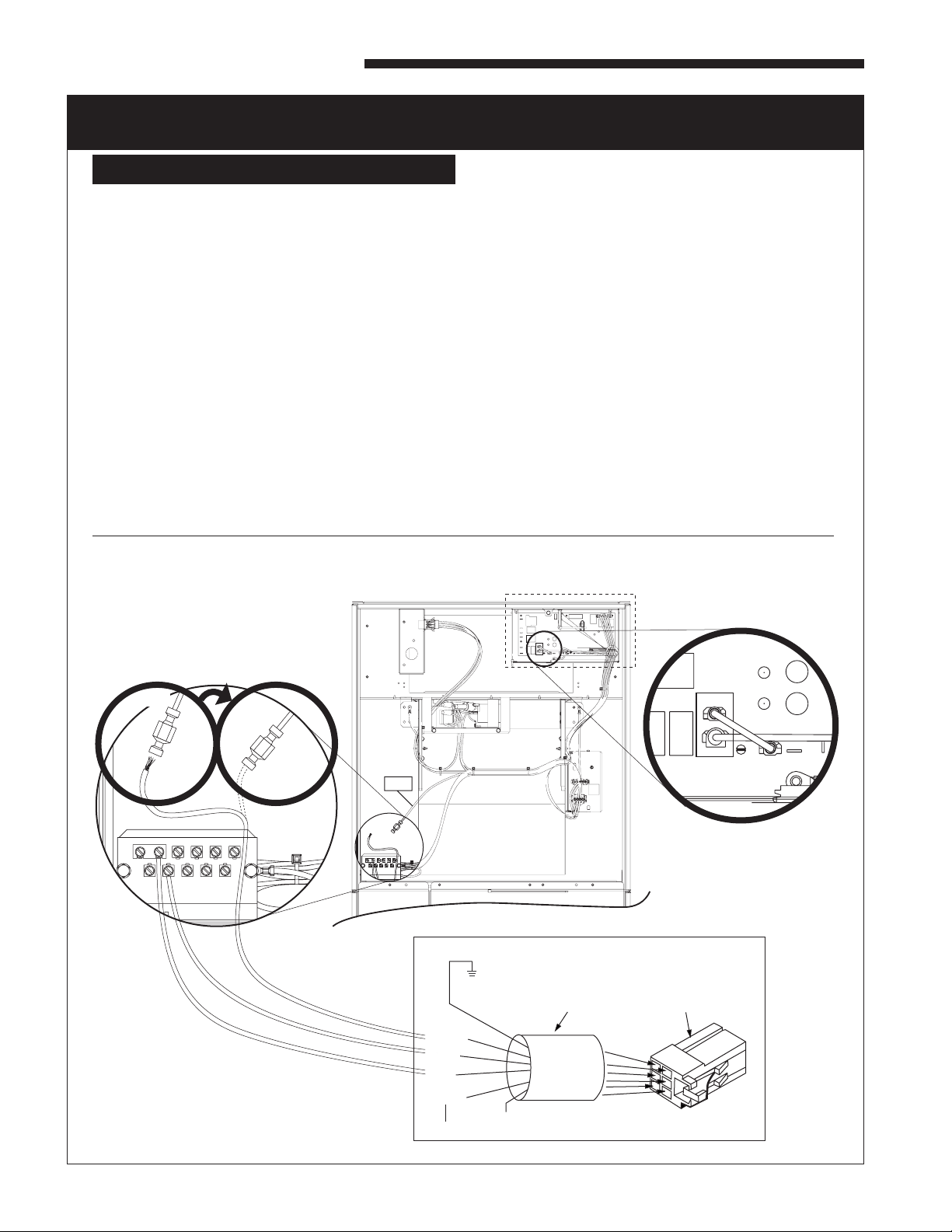
Figure 19 Side Installation Details
5. Mark the inside of the opening in the air cleaner
cabinet on the side of the furnace using the inside
edge of the air cleaner cabinet as a guide. Remove
the cabinet and cut the opening in the side of the
furnace.
NOTE: Do not use the standard furnace
indents for the
opening. The opening for the air cleaner must be larger
than the standard furnace opening. Install transition as
required for air cleaner opening to match furnace opening
as described below.
6. Position the air cleaner on the return opening of the in-
door unit with the air cleaner cabinet gasket against the
indoor unit. Check that the front of the air cleaner cabinet
is facing the front of the indoor unit.
7. Align the rear of the air cleaner ush with the rear of the
indoor unit.
8. Align the sides of the cabinet with the sides of the unit.
9. The front of the cabinet will NOT align ush with the front
of the unit.
10. Securely fasten the unit using the self-tapping sheet
metal screws provided. See Figure 19.
11. Reinstall the FIELD CHARGER and lock into place by
bending one locking tab on the cabinet. See Figure 16.
12. Reinstall the PRE-FILTER and COLLECTION CELLS.
13. Each cell must be oriented with the handles toward the
front.
14.
The door can be installed in either direction. See
Door Operation Section C.
NOTE: The door has a safety switch to ensure
power is interrupted when the door is removed.
This switch is open when the door is removed from
the cabinet. When the door is properly installed,
an actuator tab located in the cabinet will close the
switch, allowing power to the electronics.
15. Remove stickers (two stickers both are 5.5" x 7.5")
from the packet and attach to the furnace, air han-
dler, or ductwork in a location visible to the home-
owner.
16. Demonstrate Maintenance (Section H) and Door
Operation (Section C) to the homeowner.
Use inner
mounting holes
for Side Installation
Install gasket material.
Cut to length required.

8 Numbers in [brackets] are for 50 Hz international systems. Pub. No. 18-HE122D1-1-EN
Installer’s Guide
E. ELECTRICAL CONNECTIONS
The air cleaner requires 24 VAC power and indoor fan
signal to operate. A transformer adequately sized to
power both the system and air cleaner is provided with
the air cleaner. Remove the transformer in the indoor
unit and replace with the transformer provided.
NOTE:
- A 50 VA transformer is required for Trane/
American Standard Heating & Air Conditioning
furnace applications.
- For Trane/American Standard Heating & Air
Conditioning air handler applications, a 75 VA
transformer is required. Replacement of the fuse
is also needed. Remove the quick blow 5 Amp fuse
and connect the supplied 3.2 Amp slow blow fuse
assembly in its place.
NOTE: WHEN MORE THAN ONE WHOLE HOUSE
AIR CLEANER is used, the 24 volt transformer
which supplies power to the air cleaner will need to
be increased by 25 VA for each additional air cleaner
added.
NOTE: Trane/American Standard Heating & Air
Conditioning dual circuited air handlers matched
with heat pumps and Trane/American Standard
Heating & Air Conditioning oil furnaces will require
an accessory Transformer KIT# BAYTRANS12024◆
to power the air cleaner. Do NOT replace air handler
transformer with the transformer supplied with the
air cleaner.
NOTE: Provide adequate strain relief for the low
voltage cable at the indoor unit.
s
s
CAUTION
!
DO NOT attach the power/control cable to a 120 Volt
EAC tap. The air cleaner uses 24 Volt power. Fail-
ure to use 24 VAC results in permanent damage to
the air cleaner.
• Plug the air cleaner power/control cable into the air
cleaner door and route the cable into the indoor unit
low voltage wiring location.
• Connect the power/control wiring per Figures 20 &
20A.
NOTE: Wiring penetration must be sealed.
NOTE: For non-Trane/American Standard Heating
& Air Conditioning systems order a 120 VAC to 24
VAC transformer, KIT# BAYTRANS12024◆ to provide
24 volt power only to the air cleaner. Access to 120
VAC outlet is required.
• Connect the power/control wiring per Figures 20 &
20A.
NOTE: Trane/American Standard Heating & Air
Conditioning Communicating Furnaces require KIT
# BAYACCECOMM101.
NOTE: Wiring diagrams for the Communicating Air
Handler, Communicating Furnaces and Oil Furnaces
are on pages 9-10, 11-13 and 14 respectively.
D
BLUE
GREEN
BROWN
BLACK
RED
WHITE
BLUE
GREEN
BROWN
BLACK
RED
WHITE
BLUE
BROWN
BROWN
Data Line
BLACK
GRD
RED
Unused
Unused
GREEN
WHITE
Air Handler may not have a Low Voltage Terminal board. Connect Electronic Air Cleaner wires to
the Air Handler Low Voltage Color coded wires.
Install Transformer, one is supplied with the Electronic Air Cleaner, in the Furnace or Air Handler.
BLUE
Unused
GREEN
Furnace / Air Handler
BROWN /
Dataline
Indoor Unit
24 V Te rminal Strip
Unused
WHITE
RED
BLUE
GREEN
WHITE
24 V
Common
Fan Signal
Furnace
Heating Signal
R
B
W
G
D
BROWN
Data Line
BLUE
GREEN
BROWN
BLACK
RED
WHITE
The ◆represents an alpha character.
Figure 20 - Wiring Diagram
Communicating Mode
NOTE: The Black wire must be con-
nected to chassis ground to ensure
proper operation.
BAYTRANS12024◆ Transformer
• Transformer must have a grounded 120 VAC
power source. Do not defeat ground plug on
the transformer.
• Mount transformer to building structure with
the four provided wood screws.
Transformer not applicable to 50 Hz units.
NOTE: BAYTRANS12024C complies with the Cali-
fornia Code of Regulation,Title 20, Sections 1601
through 1608 dated December 2006. BAYTRAN-
S12024A with vendor’s manufacturing date codes
after 0625 (YYWW) cannot be installed in California
because the transformer does not satisfy the
requirements set forth by California Code of Regula-
tions, Title 20, Sections 1601 through 1608 dated
December 2006.

Pub. No. 18-HE122D1-1-EN Numbers in [brackets] are for 50 Hz international systems. 9
Installer’s Guide
MODES OF OPERATION
The whole house air cleaner can be connected in one
of two modes of operation; either a 24 V mode or a
communicating mode. To know how the whole house
air cleaner is set up, reference Figure 21 to nd the
amber light.
A steady amber light indicates that the unit is wired in
the 24 V mode.
A blinking amber light indicates that the unit is wired in
the communicating mode.
No light present means that the unit is not connected.
Figure 21 - Amber Light showing
Mode of Operation
BLUE
GREEN
BROWN
BLACK
RED
WHITE
Air Handler may not have a Low Voltage Terminal board. Connect Electronic Air Cleaner wires to
the Air Handler Low Voltage Color coded wires.
Install Transformer, one is supplied with the Electronic Air Cleaner, in the Furnace or Air Handler.
Figure 20A - Wiring Diagram
for 24 V Mode
NOTE: The Black wire must be con-
nected to chassis ground to ensure
proper operation.
The ◆represents an alpha character.
BAYTRANS12024◆ Transformer
BLUE
GREEN
Furnace / Air Handler
BROWN /
Dataline
Indoor Unit
24 V Te rminal Strip
WHITE
RED
BLUE
GREEN
WHITE
24 V
Common
Fan Signal
Furnace
Heating Signal
R
B
W
G
BLUE
GREEN
BROWN
BLACK
RED
WHITE
• Transformer must have a grounded 120 VAC
power source. Do not defeat ground plug on
the transformer.
• Mount transformer to building structure with
the four provided wood screws.
Transformer not applicable to 50 Hz units.
NOTE: BAYTRANS12024C complies with the Cali-
fornia Code of Regulation,Title 20, Sections 1601
through 1608 dated December 2006. BAYTRAN-
S12024A with vendor’s manufacturing date codes
after 0625 (YYWW) cannot be installed in California
because the transformer does not satisfy the require-
ments set forth by California Code of Regulations,
Title 20, Sections 1601 through 1608 dated Decem-
ber 2006.
Power Button
Amber Light
Plug 24 Volt Power / Control
Cable in here.

10 Numbers in [brackets] are for 50 Hz international systems. Pub. No. 18-HE122D1-1-EN
Installer’s Guide
Control box panel cover
(Shown removed)
PCB Detail
Indoor Unit
24V
Terminal
Strip Detail
EAC
R
24V RED
jumper wire
from EAC to R
For use with Whole House
Air Cleaner
RED
BLUE
GREEN
BLACK
GRD
Air Cleaner
Plug
BROWN /
Future Use
Power / Control
Wiring Cable and Plug
Unused
BK R OGY1 Y2
DBW1W2W3
Detach female spade terminal
from white EAC wire and
crimp to green wire
BEFORE AFTER
GREEN GREEN
WHITE
WHITE
WHITE
BK R OGY1 Y2
DBW1W2W3
GREEN
WHITE
EAC
ss
WARNING
!
HAZARDOUS VOLTAGE! DISCONNECT ALL ELECTRIC
POWER, INCLUDING REMOTE DISCONNECTS
BEFORE SERVICING. FOLLOW PROPER LOCKOUT/
TAGOUT PROCEDURES TO ENSURE THE POWER
CAN NOT BE INADVERTENTLY ENERGIZED. FAILURE
TO DISCONNECT POWER BEFORE SERVICING
COULD RESULT IN DEATH OR SERIOUS INJURY.
PROCEDURE:
1) Remove electrical power going into the air handler.
2) On the communicating systems air handler, remove
the blower access panel.
3) Remove the communicating control box cover.
4) Locate the red jumper wire which is attached from
EAC to R on the Communicating Systems PCB.
Conrm it is connected. If there is not a jumper wire
installed, then one must be installed in this location in
order for the air cleaner to function properly.
5) Replace the Communicating control box cover.
6) Locate the white wire coming from the
Communicating System Air Handler PCB labeled
“EAC”. The wire will have a male spade terminal
connected to it and a female spade terminal inserted
into the male terminal. Remove the female spade
terminal and crimp it to the green wire on the air
cleaner harness.
7) Connect the green wire from the air cleaner harness
to the white wire on the Communicating Systems Air
Hand nected to the metal air handler chassis.
10) Replace the blower access panel.
11) Reconnect electrical power to the air handler.
ELECTRICAL CONNECTIONS TO A COMMUNICATING SYSTEM AIR HANDLER
IN CONVENTIONAL 24 V MODE

Pub. No. 18-HE122D1-1-EN Numbers in [brackets] are for 50 Hz international systems. 11
Installer’s Guide
ss
WARNING
!
HAZARDOUS VOLTAGE! DISCONNECT ALL ELECTRIC
POWER, INCLUDING REMOTE DISCONNECTS
BEFORE SERVICING. FOLLOW PROPER LOCKOUT/
TAGOUT PROCEDURES TO ENSURE THE POWER
CAN NOT BE INADVERTENTLY ENERGIZED. FAILURE
TO DISCONNECT POWER BEFORE SERVICING
COULD RESULT IN DEATH OR SERIOUS INJURY.
ELECTRICAL CONNECTIONS TO A STANDARD 24 VOLT AIR HANDLER
Field wiring
O
R
B
YI
W1
YO
Y2
BK
G
W2
W3
(In)
(Out)
O
R
B
YI
W1
YO
G
W2
W3
For use with Whole House
Air Cleaner
RED
BLUE
GREEN
BLACK
GRD
Air Cleaner
Plug
BROWN /
Future Use
Power / Control
Wiring Cable and Plug
Unused
WHITE
For use with Whole House
Air Cleaner
RED
BLUE
GREEN
BLACK
GRD
Air Cleaner
Plug
BROWN /
Future Use
Power / Control
Wiring Cable and Plug
Unused
WHITE
GAM5 / A/TAM4 A/TAM7

12 Numbers in [brackets] are for 50 Hz international systems. Pub. No. 18-HE122D1-1-EN
Installer’s Guide
ss
WARNING
!
HAZARDOUS VOLTAGE! DISCONNECT ALL ELECTRIC
POWER, INCLUDING REMOTE DISCONNECTS
BEFORE SERVICING. FOLLOW PROPER LOCKOUT/
TAGOUT PROCEDURES TO ENSURE THE POWER
CAN NOT BE INADVERTENTLY ENERGIZED. FAILURE
TO DISCONNECT POWER BEFORE SERVICING
COULD RESULT IN DEATH OR SERIOUS INJURY.
PROCEDURE:
1) Remove electrical power going into the air handler.
2) On the communicating systems air handler, remove
the blower access panel.
3) Connect Red stripped wire to "R" terminal on the air
handler terminal strip.
4) Connect Blue stripped wire to "B" terminal on the air
handler terminal strip.
5) Connect the brown wire from the air cleaner harness
to the "D" terminal on the Communicating Systems
Air Handler.
6) Connect the Black wire from the air cleaner wire
harness to earth ground by attaching the wire to a
grounded screw that is connected to the metal air
handler chassis or control plate assembly.
7) The Green and White wires on the air cleaner wiring
harness are unused in this application and should be
insulated separately.
8) Replace the blower access panel.
9) Reconnect electrical power to the air handler.
10) Check air cleaner and air handler operation.
ELECTRICAL CONNECTIONS TO A COMMUNICATING SYSTEMS AIR HANDLER
IN COMMUNICATING MODE
BK R OGY1 Y2
DBW1W2W3
Indoor Unit
24V Terminal
Strip Detail
Control box panel cover
(Shown removed)
For use with Whole House
Air Cleaner
RED
BLUE
GREEN
WHITE
BK R OGY1 Y2
DBW1W2W3
Unused
Black wire to
chassis
ground
Unused
BLACK
GRD
Air Cleaner
Plug
BROWN /
Dataline
Power / Control
Wiring Cable and Plug
For use with Whole House
Air Cleaner
RED
BLUE
GREEN
WHITE
Unused
Unused
BLACK
GRD
Air Cleaner
Plug
BROWN /
Dataline
Power / Control
Wiring Cable and Plug
O
D
R
B
Y1
Y2
4TEE3C A/TAM8

Pub. No. 18-HE122D1-1-EN Numbers in [brackets] are for 50 Hz international systems. 13
Installer’s Guide
ELECTRICAL CONNECTIONS TO A COMMUNICATING FURNACE IN 24 V MODE
ssWARNING
!
HAZARDOUS VOLTAGE! DISCONNECT ALL ELECTRIC
POWER, INCLUDING REMOTE DISCONNECTS BEFORE
SERVICING. FOLLOW PROPER LOCKOUT/TAGOUT
PROCEDURES TO ENSURE THE POWER CAN NOT
BE INADVERTENTLY ENERGIZED. FAILURE TO
DISCONNECT POWER BEFORE SERVICING COULD
RESULT IN DEATH OR SERIOUS INJURY.
PROCEDURE:
1. Remove electrical power going into the furnace.
2. Removeblowerdoortoup-owordown-owfurnace.
3. Remove the two screws that secure the IFC platform to the under-
sideoftheblowerdeckonanup-owfurnaceorthe3screwsthat
securetheIFCplatformtothetoppanelonadown-owfurnace.
4. Carefully remove the IFC platform from the furnace.
5. Onboththeup-owanddown-owfurnaces,mountthe50VA
transformer supplied in the packaging with the air cleaner onto the
bottom of the IFC platform. Screws and pilot holes are provided.
Seegure.
6. Removewiringfromexisting35VAtransformerandreconnecttothe
50VAtransformer.Notethepolarityofthewiresandreconnectto
the appropriate terminals. See diagram
7. RemovetheEAC-H115VACandEAC-Nwires(whiteandblack)
out of the junction box and pull them through the grommet in the
blowerdeck.Attachtwosupplied¼”insulatedfemalequickconnect
terminals by stripping the wires and crimping the terminals onto
thewires.Attachthesewirestothe115Vterminalsofthe35VA
transformer as shown in the diagram.
8. Remove the wiring harness supplied with the air cleaner from the
packaging.Attachasupplied3/16”insulatedfemalequickconnect
terminal to the blue wire and the green wire.
9. Attachthebluewirefromtheaircleanerwiringharnesstotheopen
tabonthepiggybackterminalsuppliedintheBAYACCECOMM101.
Attachpiggybackterminaltothe35VAtransformerterminal“C”
(Common).
10. Insertthe12”bluestrippedwireundertheterminalstripscrew
marked“B/C”ontheIFCcontrolboard.Iftheapplicationalsoin-
cludesanoutdoorunit(communicatingornon-communicating),the
B/Cterminalwillrequire3wiresconnected.Forthisconnection,
rather than connecting the three wires to the low voltage terminal
striponthefurnaceIFC,createapigtailusingashortlengthof
thermostatwireandawirenut(eldsupplied)toattachtotheB/C
terminal.
11. Connect the green wire from the air cleaner wiring harness to the
24Vterminalonthe35VAtransformerlabeled“RD”.Seediagram.
12. Insert the red stripped wire from the air cleaner wiring harness un-
dertheIFCcontrolboardterminalscrewmarked“R”.Seediagram.
13. Attachtheblackstrippedwirefromtheaircleanerwiringharness
directly to ground with a screw on the furnace chassis. See dia-
gram.
14. Oncealloftheconnectionshavebeencompleted,remounttheIFC
control platform into the furnace.
15. Secure any loose wiring with wire ties.
16. ThebrownandwhitewiresfromtheEACwiringharnessare
unused in this application and should be insulated. See diagram.
17. Replace the furnace door.
18. Reconnect electrical power to the furnace.
19. Check both furnace and air cleaner operation per the furnace and
air cleaner installer guides.
BILL OF MATERIALS:
QTY:2 Screw
QTY:1 4"InsulatedCopperWire–
Blue(18AWG,AWM)
QTY:2 1/4”InsulatedFemaleQuick
Connect Terminal
QTY:2 3/16"x0.020"InsulatedFemale
Quick Connect Terminal
QTY:1 3/16"x0.020"Receptacle&Tab These instructions and listed parts are included in KIT# BAYACCECOMM101

14 Numbers in [brackets] are for 50 Hz international systems. Pub. No. 18-HE122D1-1-EN
Installer’s Guide
ELECTRICAL CONNECTIONS TO A COMMUNICATING SYSTEM FURNACE
s
s
WARNING
!
HAZARDOUS VOLTAGE! DISCONNECT ALL ELECTRIC
POWER, INCLUDING REMOTE DISCONNECTS BEFORE
SERVICING. FOLLOW PROPER LOCKOUT/TAGOUT
PROCEDURES TO ENSURE THE POWER CAN NOT
BE INADVERTENTLY ENERGIZED. FAILURE TO
DISCONNECT POWER BEFORE SERVICING COULD
RESULT IN DEATH OR SERIOUS INJURY.
PROCEDURE:
1. Remove electrical power going into the furnace.
2. Openblowerdoortoupowordownowfurnace.
3. Disconnectallwiresonthe35VAtransformer.
4. Removethe35VAtransformerfromtheIFCplatform.
5. Mountthe50VAtransformersuppliedinthepackagingwiththe
aircleanerontotheIFCplatformwherethe35VAtransformerwas
previously located. Use the sheet metal screws supplied with the
aircleanertomountthe50VAtransformer.Reconnectthe115V
and24Vwiresthatwereconnectedtothe35VAtransformeronto
the50VAtransformer.
6. ConnectRedstrippedwireto"R"terminalonthefurnacecontrol
board.
7. ConnectBluestrippedwireto"B"terminalonthefurnacecontrol
board.
8. ConnectBrownstrippedwireto"D"terminalonthefurnacecontrol
board.
9. Attachtheblackstrippedwirefromtheaircleanerwiringharness
directly to ground with a screw in the chassis.
10. Thegreenandwhitewiresontheaircleaningwiringharnessare
unused in this application and should be insulated.
11. Replace door on furnace.
12. Reconnect electrical power to the furnace.
13. Check both furnace and air cleaner operation per the furnace and air
cleaner installer guides.

Pub. No. 18-HE122D1-1-EN Numbers in [brackets] are for 50 Hz international systems. 15
Installer’s Guide
ELECTRICAL CONNECTIONS TO AN OIL FURNACE
R1
R1
THERMOSTAT FURNACE
FAN CENTER
SINGLE STAGE OIL FURNACE TO AIR CLEANER
OIL BURNER PRIMARY
NOTE 3
NOTE 2:
NOTE 2
NOTE 2
NOTE 1
NOTE 1:
Y
G
W
RH
Y
G
W
C
T
T
R
BR
G
W
B
Bk
GND
R
If thermostat being used has separate RC and
RH terminals, jumper RC and RH together.
Oil burner primary TT contacts must be isolated
using field supplied relay (RLY00925) or equivalent.
NOTE 3: The black wire (Bk) from ACCE unit must be connected
to chassis ground to ensure proper operation.
NOTE 2:
NOTE 1: If thermostat being used has separate RC and
RH terminals, jumper RC and RH together.
Oil burner primary TT contacts must be isolated
using field supplied relay (RLY00925) or equivalent.
NOTE 3: The black wire (Bk) from ACCE unit must be connected
to chassis ground to ensure proper operation.
R1
R1
THERMOSTAT AIR
CLEANER
AIR
CLEANER
VARIABLE SPEED OIL FURNACE TO AIR CLEANER
OIL BURNER PRIMARY
NOTE 3
NOTE 2
NOTE 2
NOTE 1
Y/
Y1 Y/
Y2
R/
RC
R/
RC
G
W
B
RH
G
W1
BCC
T
T
R
O
BR
G
W
B
Bk
GND
R
FURNACE
LOW VOLTAGE
TERMINAL
BLOCK
BK
Factory
Jumpered
ss
WARNING
!
HAZARDOUS VOLTAGE! DISCONNECT ALL ELECTRIC
POWER, INCLUDING REMOTE DISCONNECTS
BEFORE SERVICING. FOLLOW PROPER LOCKOUT/
TAGOUT PROCEDURES TO ENSURE THE POWER
CAN NOT BE INADVERTENTLY ENERGIZED. FAILURE
TO DISCONNECT POWER BEFORE SERVICING
COULD RESULT IN DEATH OR SERIOUS INJURY.
Refer to the diagrams below for proper connections
to an oil furnace. Consult the oil furnace installer's
guide for additional information.

16 Numbers in [brackets] are for 50 Hz international systems. Pub. No. 18-HE122D1-1-EN
Installer’s Guide
Dual Whole House Air Cleaners
In some instances, two whole house air cleaners
can be utilized to manage the overall system
operational static pressure. The gure below
shows two whole house air cleaners installed on
an upow furnace. The 24 volt transformer which
supplies power to the air cleaner will need to be
increased by 25 VA for each additional air cleaner
added.
See the wiring diagrams for information on how to
attach the wires in a two whole house air cleaner
system. The gure on the top of page 16 shows
the wiring hookup for two whole house air cleaners
attached to a furnace in conventional 24 V mode.
The gure on the bottom of page 16 shows the
wiring hookup for two whole house air cleaners
attached to a furnace in communicating mode.
Refer to the wiring diagrams on pages 8 through
14 for guidance on wiring the whole house air
cleaners to the system properly. All wires will be
run the same way for each of the two whole house
air cleaners.
ELECTRICAL CONNECTIONS FOR DUAL WHOLE HOUSE AIR CLEANER
Dual System on Furnace
Airow

Pub. No. 18-HE122D1-1-EN Numbers in [brackets] are for 50 Hz international systems. 17
Installer’s Guide
FIELD SUPPLIED 50 VA TRANSFORMER
FIELD SUPPLIED 75 VA TRANSFORMER
ELECTRICAL CONNECTIONS FOR DUAL WHOLE HOUSE AIR CLEANERS
AND FURNACE IN CONVENTIONAL 24V MODE
ELECTRICAL CONNECTIONS FOR DUAL WHOLE HOUSE AIR CLEANER AND
FURNACE IN COMMUNICATING MODE

18 Numbers in [brackets] are for 50 Hz international systems. Pub. No. 18-HE122D1-1-EN
Installer’s Guide
F. AIR CLEANER OPERATION
ssCAUTION
!
Do NOT operate the air cleaner during construction
or remodeling of a home. The air cleaner is designed
for use in normal living conditions to capture small
particles. The volume of dust and condensate in
the presence of chlorides and uorides from paint,
varnish, stains, adhesives, cleaning compounds,
and cement creates a corrosive condition which
may cause rapid deterioration of the cabinet and
internal components of the air cleaner and the air
handler/furnace.
DISPLAY FEATURES (Figure 22)
The air cleaner display can be used for several
functions:
• Provide the homeowner the operating status of the
air cleaner, including an indication the PRE-FILTER
or COLLECTION CELLS need cleaning.
• The installer accesses the SET-UP mode to
change the time to clean settings for the PRE-
FILTER and COLLECTION CELLS as well as change
the Power Level setting.
• The unit will display fault codes for the homeowner
indicating there is a problem with the air cleaner and
various fault codes for the service technician to assist
in troubleshooting the problem.
Turn the air cleaner on by pushing the POWER button.
The backlit POWER and Filter RESET buttons will
illuminate along with the rst Green LED (G1) indicating
24 Volt power is present to the air cleaner.
When the indoor fan is operating the rst LED (G1)
will slowly ash. This indicates the FIELD CHARGER
and COLLECTION CELLS have power and the unit is
operating normally. There is a 10 [12] minute time delay
between the indoor fan starting and LED (G1) ashing.
In normal operation, the air cleaner makes a slight
sound as the air passes through it and is cleaned. In
some applications, you may notice this sound coming
from the return air vent(s). If desired, this sound level
can be reduced with minimal impact on air cleaning
eciency by reducing the power setting of the FIELD
CHARGER in the SET-UP mode.
NOTE: There is a 10 [12] minute delay after the
indoor fan operates, before the air cleaner starts to
operate, each time the power to the air cleaner is
turned o/on. This can be bypassed by going into
and then out of the SET-UP mode.
G. SET-UP MODE
A combination of RED, YELLOW, and GREEN LED's
are used to indicate the following settings. See Figure
23.
• The three GREEN LED's are used to indicate PRE-
FILTER cleaning interval. This is measured in actual run
time of the indoor fan. The default setting is 2 months
[10 weeks]. See Figure 24.
• The four YELLOW LED's indicate the COLLECTION
CELLS cleaning interval. This is measured in actual run
time of the indoor fan. The default setting is 6 months
[31 weeks]. See Figure 25.
• The three RED LED's indicate the Power Level
setting. The default is maximum. See Figure 26.
INSTALLER SET-UP MODE
To enter the SET-UP Mode press and hold both the
POWER and RESET buttons for a minimum of 5 [6]
seconds. The current settings are then displayed. See
Figure 23. If this is the desired setting or at any time you
want to exit the SET-UP mode, press and hold BOTH
the POWER and RESET buttons for a minimum of 5 [6]
seconds to exit.
To change any of the settings, press the POWER button once.
PRE-FILTER SETTING (Figure 24) 24V Mode
Only.
One or more of the GREEN LED’s will come on
indicating the PRE-FILTER cleaning time setting.
Repeatedly press the RESET button to cycle through
the time options for the PRE-FILTER cleaning cycle until
the desired setting is displayed. Press the POWER
button once to accept that setting and move to the
COLLECTION CELL cleaning settings.
Figure 24 Green LED Pre-Filter Settings
* Factory Setting
Figure 22 LED Display
PRE-FILTER
RESET
CLEAN
LED's
POWER
PRE-FILTER
RESET
G1
G2
G3
Y1
Y3
Y4
R1
R2
R3
Y2
CLEAN
DIRTY
G1
G2
G3
Y1
Y3
Y4
R1
R2
R3
Y2
CLEAN
DIRTY
G1
G2
G3
Y1
Y3
Y4
R1
R2
R3
Y2
CLEAN
DIRTY
One Month
[5 Weeks]
Two Months *
[10 Weeks]
Three Months
[15 Weeks]
Figure 23 Factory Settings
G1
G2
G3
Y1
Y3
Y4
R1
R2
R3
Y2
CLEAN
DIRTY
Power Level
Collection Cell
Pre-Filter
FIELD CHARGER Power
Maximum
COLLECTION CELL
6 Months [31 weeks]
PRE-FILTER
2 Months [10 weeks]
Factory settings

Pub. No. 18-HE122D1-1-EN Numbers in [brackets] are for 50 Hz international systems. 19
Installer’s Guide
Flashing red light indicates
that it is time to clean the
COLLECTION CELLS
Red light indicates that it is
time to clean the PRE-
FILTER
CELL CLEANING SETTING (Figure 25)
One or more of the YELLOW LED’s will come on
indicating the COLLECTION CELL cleaning time setting.
Repeatedly press the RESET button to cycle through
the time options for the COLLECTION CELL cleaning
cycle until the desired setting is displayed. Press the
POWER button once to accept that setting and move to
the Field Charger Power Level Settings.
Figure 25 Yellow LED Collection Cells Settings
*Factory Setting
FIELD CHARGER POWER LEVEL
The RED LED lights are used to set the Power Level
of the FIELD CHARGER for maximum, medium, or
minimum. The number of illuminated RED LED lights
indicates the current setting. The factory setting is for
maximum.
Lower settings will reduce the slight sound emitted by
the unit with minimal loss of air cleaning eciency, if
desired.
H. MAINTENANCE
ss
CAUTION
!
Before cleaning the coil or ducts in the air handler
or furnace, remove the COLLECTION CELLS, FIELD
CHARGER, and PRE-FILTER from the air cleaner.
Chemicals used during the cleaning of the air
handler, furnace, or ductwork can damage the air
cleaner components and degrade the performance
of the air cleaner.
For maximum eciency, the COLLECTION CELLS
and PRE-FILTER should be inspected and cleaned as
prescribed in this Installer's Guide.
The FIELD CHARGER should only be removed and
cleaned annually by a qualied service professional.
CLEANING
Cleaning Instructions:
The air cleaner utilizes a PRE-FILTER and
COLLECTION CELLS. The purpose of the PRE-FILTER
is to capture large particles before they enter the
COLLECTION CELLS which allows the collection cells
to work more eciently.
1. Turn the air conditioning system o at the Comfort
Control (thermostat).
s
sWARNING
!
High Voltage is present within the air cleaner for
operation. Before removing the Power Door, turn
the power o and wait at least 15 seconds to allow
voltage to discharge. Failure to follow instructions
could result in death or serious personal injury.
2. Turn o power to the air cleaner by pushing and hold-
ing the POWER button for three seconds. The LED’s
will remain on until the voltage has discharged and
it is safe to remove the door. This requires approxi-
mately 15 seconds. Do not remove the door until
all the lights are o.
3. Disconnect the power/control cable.
4. Remove the Door Assembly from Whole Home Air
Cleaner by pulling away from the unit assembly.
Place on the at and clean working surface with inte-
rior components facing up. See Figure 28.
5. Remove the PRE-FILTER (Figure 29) and/or the
COLLECTION CELLS (Figure 30) from the air
cleaner.
G1
G2
G3
Y3
Y4
R1
R2
R3
Y2
CLEAN
DIRTY
G1
G2
G3
Y3
Y4
R1
R2
R3
Y2
CLEAN
DIRTY
Y1
G1
G2
G3
Y3
Y4
R1
R2
R3
Y2
CLEAN
DIRTY
Y1 Y1
G1
G2
G3
Y3
Y4
R1
R2
R3
Y2
CLEAN
DIRTY
Y1
Two Months
[10 Weeks]
Four Months
[20 Weeks]
Six Months*
[31 Weeks]
Nine Months
[46 Weeks]
PRE-FILTER
RESET
CLEAN
PRE-FILTER
Figure 27 Pre-Filter Light
FIELD CHARGER POWER LEVEL
SETTING (Figure 26)
One or more of the RED LED lights will illuminate. To
change the Power Level setting, press the RESET
button until the desired setting is indicated.
To save your new settings and exit the SET-UP mode,
press and hold BOTH the POWER and lter RESET
buttons for a minimum of 5 [6] seconds.
Minimum Medium Maximum*
G1
G2
G3
Y1
Y3
Y4
R1
R2
R3
Y2
CLEAN
DIRTY
G1
G2
G3
Y1
Y3
Y4
R1
R2
R3
Y2
CLEAN
DIRTY
G1
G2
G3
Y1
Y3
Y4
R1
R2
R3
Y2
CLEAN
DIRTY
Figure 26 Red LED Power Level Settings
*Factory Setting

20 Numbers in [brackets] are for 50 Hz international systems. Pub. No. 18-HE122D1-1-EN
Installer’s Guide
Figure 29 Pre-Filter
Figure 30 Collection Cells
VACUUM CLEANING
Vacuuming is the preferred method to clean the PRE-
FILTER and COLLECTION CELLS. It is recommended
that the PRE-FILTER and the COLLECTION CELLS
be vacuumed outside the home to ensure particles on
the lters are not reintroduced into the air. Persons
highly sensitive to the collected particles should wear
appropriate respiratory protection while cleaning.
PRE-FILTER –
It is time to clean the PRE-FILTER when the red “PRE-
FILTER” light (shown in Figure 27) is illuminated.
The air cleaner is factory set to notify the home owner
to clean the PRE-FILTER every two months [10 weeks]
of actual run time of the air cleaner. This notication
can be changed by the installer/home owner to 1 month
[5 weeks] or 3 months [15 weeks] depending on the
conditions in the home (pets, smokers, etc.). Please
see “SET-UP MODE” (Page 13) to change the factory
settings.
1. Using a vacuum hose, vacuum in even strokes
across the length of the PRE-FILTER. After
vacuuming the entire PRE-FILTER using
even strokes going in one direction, repeat
the process using even strokes going in the
opposite direction as shown in Figure 31.
NOTE: Do NOT replace the plastic PRE-FILTER with
a metal type PRE-FILTER. A metal PRE-FILTER will
cause reduction in eciency and potential failure of
the electronics in the air cleaner.
COLLECTION CELLS
The clean/dirty LED light bar indicator will illuminate
as the system cleans the air. The LED lights will
progress from green to yellow and then to red. When
the last red indicator is ashing, it is time to clean the
COLLECTION CELLS (see Figure 29). The air cleaner
is factory set to notify the home owner to clean the
COLLECTION CELLS every six months [31 weeks] of
actual run time of the air cleaner. This notication can
be changed by the installer/home owner to 2 months,
4 months, 6 months, or 9 months [10, 20, 31, or 46
weeks] depending on the conditions in the home (pets,
smokers, etc.). Please see “SET-UP MODE” (Page 13)
to change the factory settings.
1. Using a vacuum hose, vacuum in even strokes
Figure 31 Vacuuming the Pre-lter
Figure 28 Rotating Door Latches
This manual suits for next models
12
Table of contents