manuals.online logo
Brands
  1. Home
  2. •
  3. Brands
  4. •
  5. IntesisBox
  6. •
  7. Recording Equipment
  8. •
  9. IntesisBox SM-RC-MBS-1 User manual

IntesisBox SM-RC-MBS-1 User manual

Interfaz SM-RC-MBS-1 FW:0.3
Interface SM-RC-MBS-1 FW:0.3
1 / 2
© Intesis Software S.L.U. - Todos los derechos reservados/ All rights reserved
IntesisBox es una marca registrada de / is a registred trademark of Intesis Software SLU
La información en este documento puede variar sin previo aviso. / This information is subject to change without notice.
Doc. Rev.1.2
URL
email
Phone
http://www.intesisbox.com
info@intesisbox.com
+34 938047134
•Esta interfaz debe ser instalada por personal técnico
acreditado (electricista, instalador o personal técnico
cualificado) y siguiendo todas las instrucciones de
seguridad.
•La interfaz debe ser instalada en una ubicación con acceso
restringido.
•Antes de manipular en el interior del A.A., asegúrese de
que está completamente desconectado de la red eléctrica.
•En caso de instalación mural de la interfaz junto a la unidad
interior de A.A., fije la interfaz de forma segura siguiendo
las instrucciones del diagrama de abajo.
•En caso de instalación de la interfaz en el interior de la
unidad interior de A.A., fije la interfaz y los cables de
comunicación preferiblemente en algún punto de la carcasa
de plástico de forma que no interfieran al libre movimiento
de partes móviles y alejados al máximo de tubos
conductores de líquidos y cables eléctricos.
•
•This interface must be installed by accredited technical
personnel (electrician, installer or qualified technical
personnel) and they must follow all the safety instructions.
•This interface must be installed in an acces restricted
location.
•Before manipulating the AC indoor unit, make sure it is
completely disconnected from Mains Power.
•In case of wall mounting of the interface next to the AC
indoor unit, attach the interface safely following the
instructions of the diagram below.
•In case of installation of the interface inside the AC indoor
unit, attach the interface and communication cables
preferably to any proper point of the plastic cover of each
unit and take care to not block free movement of mobile
parts. Locate them as far as possible from pipes containing
liquids and power cables.
•Desconecte el aire acondicionado de la red eléctrica.
•Fije la interfaz a la pared junto a la unidad interior del aire
acondicionado siguiendo las instrucciones del diagrama de
abajo o dentro de la unidad interior del aire acondicionado
(respete las instrucciones de seguridad anteriores).
•Conecte la interfaz al bus F3F4 en cualquier punto del
mismo. El bus F3F4 es el bus que conecta la unidad interior
de aire acondicionado y el mando por cable, es un par de
hilos que se conectan los terminales F3F4, este bus tiene
polaridad.
•Conecte la interfaz al bus V1V2 en cualquier punto del
mismo con un par de hilos.
•Conecte el bus EIA-485 al conector EIA485 de la interfaz.
Respete la polaridad.
•Tape la unidad interior del aire acondicionado y vuelva a
conectarla a la red eléctrica.
•Siga las instrucciones del Manual de Usuario.
•Siga las instrucciones de la página siguiente para
configurar la interfaz a través de los micro interruptores.
•Disconnect the air conditioning from the Mains Power.
•Attach the interface next to the AC indoor unit (wall
mounting) following the instructions of the diagram below or
install it inside the AC indoor unit (respect the safety
instructions given above).
•Connect the interface to F3F4 bus in any point of the bus.
The F3F4 bus is the bus that connects the AC indoor unit
and the wired remote controller, is a two-wire bus
connecting terminals F3F4 of both, this F3F4 connection has
specific polarity.
•Connect the interface to V1V2 bus in any point of the bus
using a two-wire cable.
•Connect the EIA-485 bus to the connector EIA485 of the
interface.
•Close the AC indoor unit and reconnect it to Mains Power.
•Follow the instructions on the User’s Manual to configure
and commission the interface.
•Follow the instructions of the next page to configure the
interface through on-board DIP-switches.
WARNING
ATENCIÓN
Siga atentamente estas instrucciones de seguridad e
instalación. Un manejo inadecuado puede ocasionar daños
graves para su salud y daños irreparables en la interfaz y/o
en la unidad interior del aire acondicionado.
Follow carefully this safety and installation instructions. Not
proper work may lead to a serious damage for your health and
may harm seriously the interface and/or the AC indoor unit.
IMPORTANTE: La máxima distancia entre el SM-RC-MBS-1 y los
terminales F3F4 V1V2 es de 100 metros (328.08 pies). Consulte
el manual del aire acondicionado para más detalles.
NOTA: En algunas unidades interiores no existe el conector F3F4
y en su lugar existen dos cables para la conexión del Control
remoto. Utilice dichos cables para conectar el bus F3F4. Consulte
el Manual de Usuario de su unidad interior para más información.
IMPORTANTE: Si se conecta el mando del fabricante al mismo
bus, la comunicación puede perderse.
IMPORTANT: The maximum distance between SM-RC-MBS-1 and
terminals F3F4 V1V2 is 100 meters (328.08 ft). Check the manual
of the AC indoor unit for more details.
NOTE: In some indoor unit models, the F3F4 bus is not available.
In its place, there is a pair of cables to connect the Remote
Controller. Use these cables to connect the F3F4 bus. Check your
indoor unit’s User Manual for more information.
IMPORTANT: If a wired remote controller of the AC manufacturer
is connected in the same bus, communication may shut down.
El Manual de Usuario está disponible en:
https://www.intesisbox.com/en/samsung-modbus-vrf-no-nasa-sm-rc-mbs-1/gateway/
The User’s Manual is available at:
https://www.intesisbox.com/en/samsung-modbus-vrf-no-nasa-sm-rc-mbs-1/gateway/
Instrucciones de seguridad
Safety intructions
Instrucciones de instalación
Installation instructions
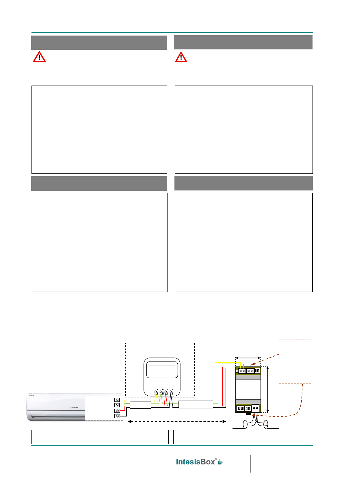
90 mm / 3.5”
IntesisBox®
SM-RC-MBS-1
MODBUS RTU
EIA-485
Bus
EIA485
A+ B-
F3 F4 V1 V2
AC Unit Power
53 mm / 2.1”
Para fijación mural
extraiga hacia fuera
las grapas superior
e inferior hasta oir
el "click".
For wall mounting
extract the upper
and down staples
until you hear the
"click".
F3F4 V1V2
Unidad interior de A.A.
AC Indoor Unit
(No es obligatorio tenerlo en la red)
(It is not mandatory to have it in the network)
Conexión al bus F3F4 V1V2.
Cable de cuatro hilos.
Connection to F3F4 V1V2 bus.
Four wire cable.
Remote Controller / Control Remoto
Samsung
F3
F4
V1
V2
Internal
Electronic
control board
Tarjeta de
Control electronico
Max. 100 m / 328.08 ft
Interfaz SM-RC-MBS-1 FW:0.3
Interface SM-RC-MBS-1 FW:0.3
2 / 2
© Intesis Software S.L.U. - Todos los derechos reservados/ All rights reserved
IntesisBox es una marca registrada de / is a registred trademark of Intesis Software SLU
La información en este documento puede variar sin previo aviso. / This information is subject to change without notice.
Doc. Rev.1.2
URL
email
Phone
http://www.intesisbox.com
info@intesisbox.com
+34 938047134
IMPORTANTE: Es necesario resetear el equipo (quitar tensión) tras modificar
la configuración de los micro interruptores para que ésta se aplique.
IMPORTANT: It is required to reboot or power cycle the interface every time the
DIP switch configuration changes.
SW1-P1..4
Descripción
Description
SW3-P7..8
SW4-P3
Descripción
Description
SW4-P1..2-4
Descripción
Description
Esclavo –Un Control Remoto Samsung debe ser presente
en elbus F3F4 V1V2 configurado como Master (V. defecto)
Slave –A Samsung Remote Controller must be present in
the F3F4 V1V2 bus, being configured this one as Master
(Default value)
2400bps
Los valores de temperatura en los registros Modbus se
representan en decigrados (x10)
Temperature values in Modbus register are represented in
decidegrees (x10)
Maestro –No se necesita un Control Remoto Samsung en
el bus F3F4 V1V2. Si este existe, debe ser Esclavo
Master –A Samsung Remote Controller not needed in the
F3F4 V1V2 bus. It it exists, it must be configured as Slave.
4800bps
Los valores de temperatura en los registros Modbus se
representan en grados (x1) (Valor por defecto).
Temperature values in Modbus register are represented in degrees
(x1) (Default value).
Reservado (Valor por defecto)
Not used (Default value)
9600bps
(valor por defecto /
default value)
Los valores de temperatura en los registros Modbus se
representan en grados Fahrenheit
Temperature values in Modbus register are represented in
Fahrenheit degrees
Reservado
Not used
19200bps
Los valores de temperatura en los registros Modbus se
representan en grados Celsius (Valor por defecto)
Temperature values in Modbus register are represented in Celsius
degrees (Default value)
Reservado (Valor por defecto)
Not used (Default value)
38400bps
Resistencia interna de 120Ωconectada al bus EIA-485
Internal termination resistor of 120Ω connected to EIA-485 bus
Reservado
Not used
57600bps
Bus EIA-485 sin resistencia de terminación (Valor por defecto).
EIA-485 bus without termination resistor (Default value).
Reservado (Valor por defecto)
Not used (Default value)
76800bps
Reservado
Not used
115200bps
Dirección de esclavo Modbus - Modbus Slave address
Direcc
Add
SW3-P1..6
Direcc
Add
SW3-P1..6
Direcc
Add
SW3-P1..6
Direcc
Add
SW3-P1..6
Direcc
Add
SW3-P1..6
Direcc
Add
SW3-P1..6
0
11
22
33
44
55
1
12
23
34
45
56
2
13
24
35
46
57
3
14
25
36
47
58
4
15
26
37
48
59
5
16
27
38
49
60
6
17
28
39
50
61
7
18
29
40
51
62
8
19
30
41
52
63
9
20
31
42
53
10
21
32
43
54
Configuración del número de esclavo Modbus y baudios.
Configuration of Modbus Slave number and baud rate.
Configuración de los baudios, magnitud temperatura (x1/x10), unidades de
temperatura (ºC/ºF) y resistencia de terminación de EIA-485.
Configuration of baud rate, temperature magnitude (x1/x10), temperature
units (Cº/Fº) and termination resistor for EIA-485.
IntesisBox®
SM-RC-MBS-1
EIA485
A+ B-
F3 F4
AC Unit
SW3
SW4
SW1
1 2 3 4
SW1
1 2 3 4
SW4
1 2 3 4 5 6 7 8
SW3
Configuración Maestro/Esclavo
Master/Slave configuration
ON
ON
ON
ON
ON
ON
ON
ON
ON
ON
ON
Configuración por micro interruptores
Configuration through DIP switches
ON
ON
ON
ON
ON
ON
ON
ON
ON
ON
ON
ON
ON
ON
ON
ON
ON
ON
ON
ON
ON
ON
ON
ON
ON
ON
ON
ON
ON
ON
ON
ON
ON
ON
ON
ON
ON
ON
ON
ON
ON
ON
ON
ON
ON
ON
ON
ON
ON
ON
ON
ON
ON
ON
ON
ON
ON
ON
ON
ON
ON
ON
ON
ON
ON
ON
ON
ON
ON
ON
ON
ON
ON
ON
ON
ON
ON
ON
ON
ON
ON
ON
ON
ON
ON
ON
V1 V2
AC Unit

Other IntesisBox Recording Equipment manuals

IntesisBox LG-RC-MBS-1 User manual

IntesisBox

IntesisBox LG-RC-MBS-1 User manual

IntesisBox HI-AW-KNX-1 User manual

IntesisBox

IntesisBox HI-AW-KNX-1 User manual

IntesisBox HA-AC-KNX-16 User manual

IntesisBox

IntesisBox HA-AC-KNX-16 User manual

IntesisBox FJ-RC-MBS-1 User manual

IntesisBox

IntesisBox FJ-RC-MBS-1 User manual

IntesisBox ME-AC-BAC-1 User manual

IntesisBox

IntesisBox ME-AC-BAC-1 User manual

IntesisBox PA-AC-BAC-1 Setup guide

IntesisBox

IntesisBox PA-AC-BAC-1 Setup guide

IntesisBox LG-RC-WMP-1 User manual

IntesisBox

IntesisBox LG-RC-WMP-1 User manual

IntesisBox DK-AC-MBS-1 User manual

IntesisBox

IntesisBox DK-AC-MBS-1 User manual

IntesisBox MD-AC-MBS-1 User manual

IntesisBox

IntesisBox MD-AC-MBS-1 User manual

IntesisBox ME-AC-MBS-1 User manual

IntesisBox

IntesisBox ME-AC-MBS-1 User manual

IntesisBox PA-RC2-MBS-1 User manual

IntesisBox

IntesisBox PA-RC2-MBS-1 User manual

IntesisBox KNX Series User manual

IntesisBox

IntesisBox KNX Series User manual

IntesisBox TO-RC-MBS-1 User manual

IntesisBox

IntesisBox TO-RC-MBS-1 User manual

IntesisBox PA-AW-KNX-1 User manual

IntesisBox

IntesisBox PA-AW-KNX-1 User manual

IntesisBox PA-AC-MBS-1 User manual

IntesisBox

IntesisBox PA-AC-MBS-1 User manual

IntesisBox PA-RC2-BAC-1 User manual

IntesisBox

IntesisBox PA-RC2-BAC-1 User manual

IntesisBox IS-IR-WMP-1 User manual

IntesisBox

IntesisBox IS-IR-WMP-1 User manual

IntesisBox ME-AC-BAC-1L User manual

IntesisBox

IntesisBox ME-AC-BAC-1L User manual

IntesisBox DK-RC-WMP-1 User manual

IntesisBox

IntesisBox DK-RC-WMP-1 User manual

IntesisBox PA-AW2-MBS-1 User manual

IntesisBox

IntesisBox PA-AW2-MBS-1 User manual

IntesisBox TO-RC-BAC-1 User manual

IntesisBox

IntesisBox TO-RC-BAC-1 User manual

IntesisBox MH-RC-MBS-1 User manual

IntesisBox

IntesisBox MH-RC-MBS-1 User manual

IntesisBox MH-RC-MBS-1 User manual

IntesisBox

IntesisBox MH-RC-MBS-1 User manual

IntesisBox MH-RC-BAC-1 User manual

IntesisBox

IntesisBox MH-RC-BAC-1 User manual

Popular Recording Equipment manuals by other brands

Inter-m PG-6104 Operation manual

Inter-m

Inter-m PG-6104 Operation manual

JPS RSP-Z2 quick start guide

JPS

JPS RSP-Z2 quick start guide

AMX AXB-DMX512 DMX512 INTERFACE instruction manual

AMX

AMX AXB-DMX512 DMX512 INTERFACE instruction manual

Telos Alliance Axia QUASAR XR user manual

Telos Alliance

Telos Alliance Axia QUASAR XR user manual

LaLaLand CS Midi Series installation manual

LaLaLand

LaLaLand CS Midi Series installation manual

JPS PTG-10 Installation and operation manual

JPS

JPS PTG-10 Installation and operation manual

Enginko MCF-LW06010B manual

Enginko

Enginko MCF-LW06010B manual

Yamaha NUAGE Setup guide

Yamaha

Yamaha NUAGE Setup guide

OTARI MX-5050BII Series instruction manual

OTARI

OTARI MX-5050BII Series instruction manual

Marantz DR6050 series Service manual

Marantz

Marantz DR6050 series Service manual

SMC Networks EX250 Series Operation manual

SMC Networks

SMC Networks EX250 Series Operation manual

Fostex M20 owner's manual

Fostex

Fostex M20 owner's manual

Korg MicroKORG XL quick start guide

Korg

Korg MicroKORG XL quick start guide

Bose ControlSpace EP40-D installation guide

Bose

Bose ControlSpace EP40-D installation guide

Aritech ATS1741 quick start guide

Aritech

Aritech ATS1741 quick start guide

SOMFY Neocontrol SLIMTOUCH NEO-SLT-BL quick start guide

SOMFY

SOMFY Neocontrol SLIMTOUCH NEO-SLT-BL quick start guide

ANTUMBRA 6MIX Building instructions

ANTUMBRA

ANTUMBRA 6MIX Building instructions

Toa IP-3000SM Operation instructions

Toa

Toa IP-3000SM Operation instructions

manuals.online logo
manuals.online logoBrands
  • About & Mission
  • Contact us
  • Privacy Policy
  • Terms and Conditions

Copyright 2025 Manuals.Online. All Rights Reserved.