manuals.online logo
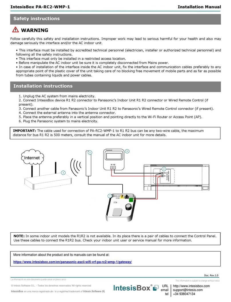
Brands
  1. Home
  2. •
  3. Brands
  4. •
  5. IntesisBox
  6. •
  7. Recording Equipment
  8. •
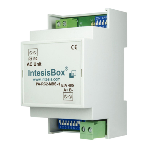
  9. IntesisBox PA-AW-MBS-1 User manual

IntesisBox PA-AW-MBS-1 User manual

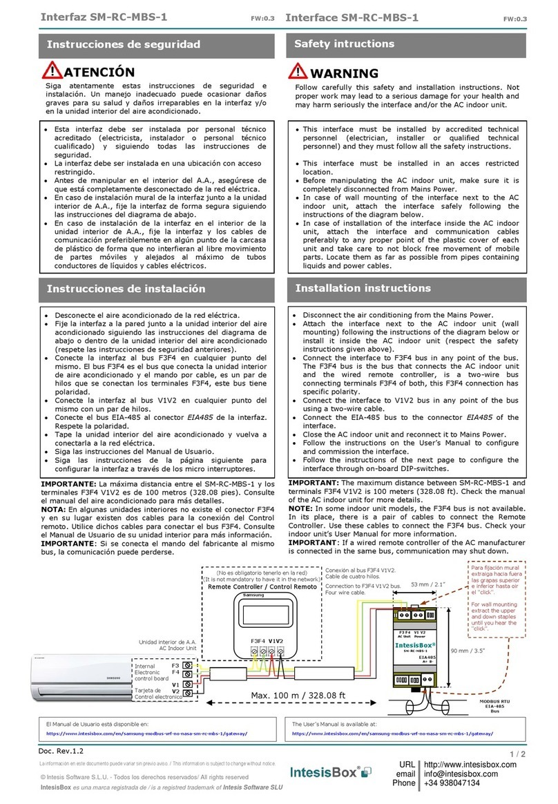
Interfaz PA-AW-MBS-1
Interface PA-AW-MBS-1
1 / 2
© Intesis Software S.L. - Todos los derechos reservados/ All rights reserved
IntesisBox es una marca registrada de / is a registred trademark of Intesis Software SL
URL
email
tel
http://www.intesis.com
[email protected]m
+34 938047134
La información en este documento puede variar sin previo aviso.
This information is subject to change without notice.
Doc. r1
Bibloc
Monobloc
Esta interfaz debe ser instalado por personal técnico
acreditado (electricista, instalador, o personal técnico
cualificado) y siguiendo todas las instrucciones de
seguridad.
Antes de manipular en el interior del aire
acondicionado, asegúrese de que está
completamente desconectado de la red eléctrica.
En caso de instalación mural del interfaz junto a la
unidad interior del aire acondicionado, fije la interfaz
de forma segura siguiendo las instrucciones del
diagrama de abajo.
Instrucciones de seguridad
Safety instructions
This interface must be installed by accredited
technical personnel (electrician, installer, or
Mitsubishi Electric technical personnel) and following
all the safety instructions.
Before manipulate the AC indoor unit be sure it is
completely disconnected from Mains power.
In case of wall mounting of the interface beside the
AC indoor unit, fix the interface safely following the
instructions of the diagram below.
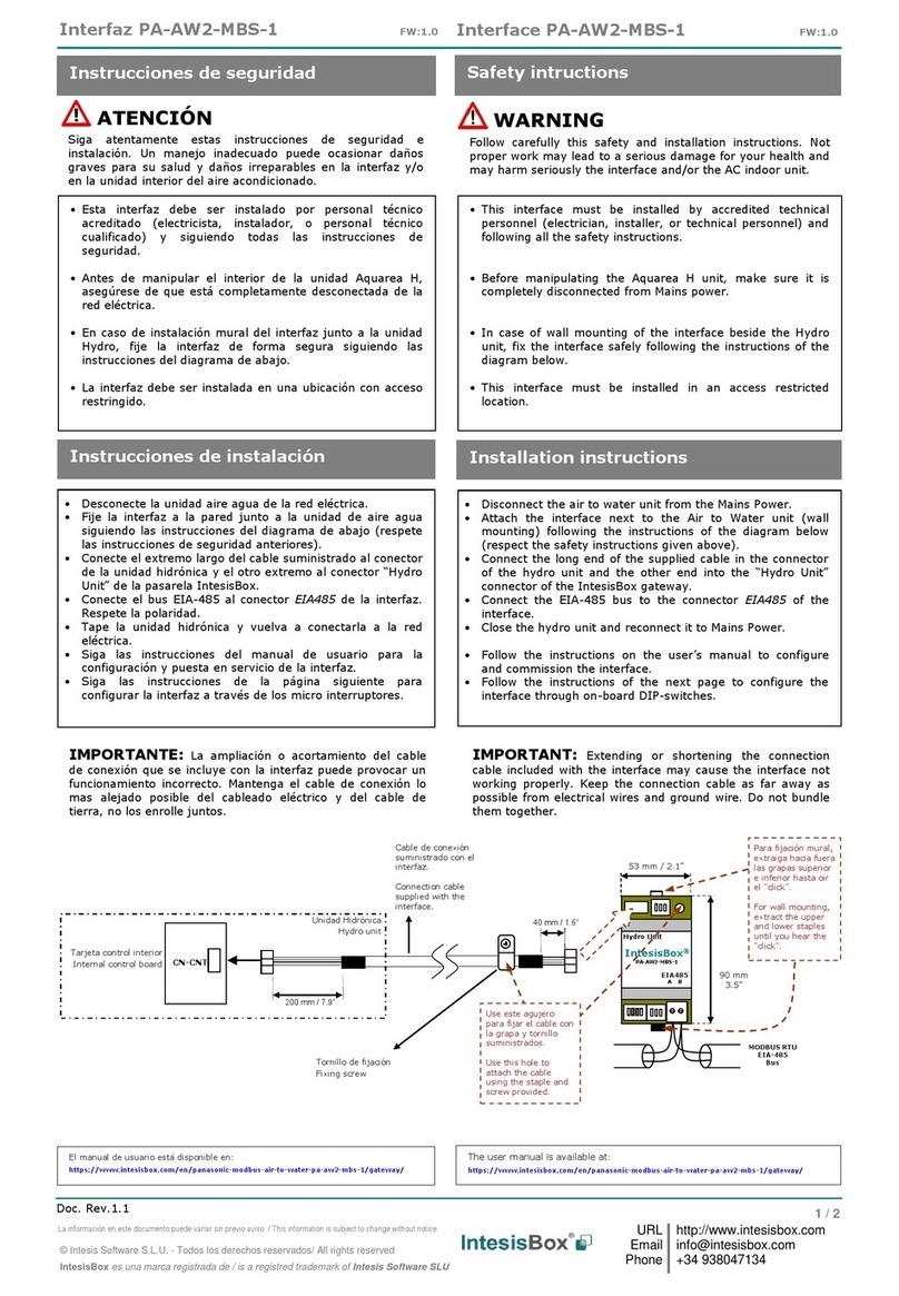
Desconecte el sistema Aquarea de la red eléctrica.
Fije el interfaz a la pared junto a la unidad interior
del aire acondicionado siguiendo las instrucciones del
diagrama de abajo o dentro de la unidad interior del
aire acondicionado (respete las instrucciones de
seguridad anteriores).
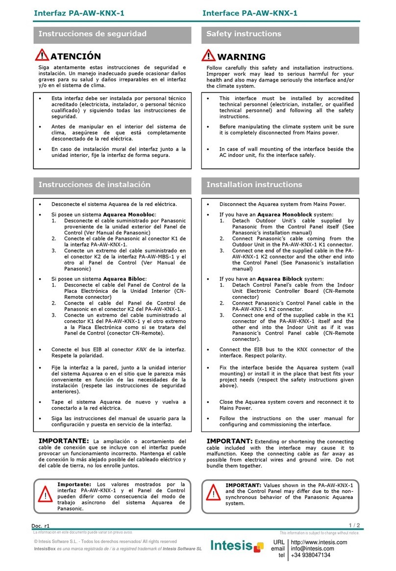
Si posee un sistema Aquarea Monobloc:
1. Desconecte el cable suministrado por Panasonic
proveniente de la unidad exterior del Panel de
Control (Ver Manual de Panasonic)
2. Conecte el cable de Panasonic al conector K1 de
la interfaz PA-AW-MBS-1.
3. Conecte un extremo del cable suministrado en
el conector K2 de la interfaz PA-AW-MBS-1 y el
otro al Panel de Control (Ver Manual de
Panasonic)
Si posee un sistema Aquarea Bibloc:
1. Desconecte el cable del Panel de Control de la
Placa Electrónica de la Unidad Interior (CN-
Remote connector)
2. Conecte el cable del Panel de Control de
Panasonic en el conector K2 del PA-AW-MBS-1.
3. Conecte un extremo del cable suministrado al
conector K1 del PA-AW-MBS-1 y el otro extremo
a la Placa Electrónica como si se tratara del
Panel de Control (CN-Remote connector).
Conecte el bus EIA485 al conector EIA485 de la
interfaz. Respete la polaridad.
Tape la unidad interior del aire acondicionado y
vuelva a conectarlo a la red eléctrica.
Siga las instrucciones del manual de usuario para la
configuración y puesta en servicio del interfaz.
Siga las instrucciones de la página siguiente para
configurar la interfaz a través de los Micro
Interruptores.
Instrucciones de instalación
Installation instructions
Disconnect the Aquarea system from Mains Power.
Fix the interface beside the AC indoor unit (wall
mounting) following the instructions in the diagram
below or install it inside the AC indoor unit (respect
the safety instructions given above).
If you have an Aquarea Monoblock system:
1. Detach Outdoor Unit’s cable supplied by
Panasonic from the Control Panel itself (See
Panasonic’s installation manual)
2. Connect Panasonic’s cable coming from the
Outdoor Unit in the PA-AW-MBS-1 K1 connector.
3. Connect one end of the supplied cable in the PA-
AW-MBS-1 K2 connector and the other end into
the Control Panel (See Panasonic’s installation
manual)
If you have an Aquarea Biblock system:
1. Detach Control Panel’s cable from the Indoor
Unit Electronic Controller Board (CN-Remote
connector)
2. Connect Panasonic’s Control Panel cable in the
PA-AW-MBS-1 K2 connector.
3. Connect one end of the supplied cable in the K1
connector of the PA-AW-MBS-1 itself and the
other end into the Indoor Unit as if it was
Panasonic’s Control Panel cable (CN-Remote
connector).
Connect the EIA485 bus to the connector EIA485 of
the interface.
Close the AC indoor unit and reconnect it to Mains
Power.
Follow the instructions on the user manual for
configuring and commissioning the interface.
Follow the instructions of the next page to configure
the interface through on-board DIP-switches.
WARNING
ATENCIÓN
Siga atentamente estas instrucciones de seguridad e
instalación. Un manejo inadecuado puede ocasionar daños
graves para su salud y daños irreparables en el interfaz
y/o en la unidad interna del aire acondicionado.
Follow carefully this safety and installation instructions.
Improper work may lead to serious harmful for your
health and also may damage seriously the interface and/or
the AC indoor unit.
IntesisBox®
PA-AW-MBS-1
Modbus RTU
EIA485
Bus
EIA485
A+ -B
K2 K1
AW Unit
IntesisBox®
PA-AW-MBS-1
Modbus RTU
EIA485
Bus
EIA485
A+ B-
K2 K1
AW Unit
Cable de Panasonic /
Panasonic Cable
Cable suministrado /
Supplied cable
Cable de Panasonic /
Panasonic Cable
Cable suministrado /
Supplied cable
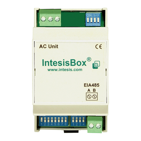
Interfaz PA-AW-MBS-1
Interface PA-AW-MBS-1
2 / 2
© Intesis Software S.L. - Todos los derechos reservados/ All rights reserved
IntesisBox es una marca registrada de / is a registred trademark of Intesis Software SL
URL
email
tel
http://www.intesis.com
[email protected]m
+34 938047134
La información en este documento puede variar sin previo aviso.
This information is subject to change without notice.
Doc. r1
*Los micro interruptores en S1 actualmente no se utilizan
*Micro switches in S1 are not currently in use
S3 - Dirección de esclavo modbus y baudios - Modbus slave address and baudrate
Direcc
Add
Interruptores
Switches
1 2 3 4 5 6 7 8
Direcc
Add
Interruptores
Switches
1 2 3 4 5 6 7 8
Direcc
Add
Interruptores
Switches
1 2 3 4 5 6 7 8
Direcc
Add
Interruptores
Switches
1 2 3 4 5 6 7 8
Direcc
Add
Interruptores
Switches
1 2 3 4 5 6 7 8
Direcc
Add
Interruptores
Switches
1 2 3 4 5 6 7 8
Direcc
Add
Interruptores
Switches
1 2 3 4 5 6 7 8
Direcc
Add
Interruptores
Switches
1 2 3 4 5 6 7 8
0
x x
8
x x
16
x x
24
x x
32
x x
40
x x
48
x x
56
x x
1*
x x
9
x x
17
x x
25
x x
33
x x
41
x x
49
x x
57
x x
2
x x
10
x x
18
x x
26
x x
34
x x
42
x x
50
x x
58
x x
3
x x
11
x x
19
x x
27
x x
35
x x
43
x x
51
x x
59
x x
4
x x
12
x x
20
x x
28
x x
36
x x
44
x x
52
x x
60
x x
5
x x
13
x x
21
x x
29
x x
37
x x
45
x x
53
x x
61
x x
6
x x
14
x x
22
x x
30
x x
38
x x
46
x x
54
x x
62
x x
7
x x
15
x x
23
x x
31
x x
39
x x
47
x x
55
x x
63
x x
* Valor por defecto - Default value
Valor binario
Binary value
b0…b8
Valor decimal
Decimal value
Interruptores
Switches
1 2 3 4 5 6 7 8
Descripción
Description
xxxxxx00
0
x x x x x x 
2400bps
xxxxxx10
1
x x x x x x 
4800bps
xxxxxx01
2
x x x x x x 
9600bps (valor por defecto - default value)
xxxxxx11
3
x x x x x x 
19200bps
S1 –No utilizado –Not used
La versión actual de PA-AW-MBS-1 no utiliza este conjunto de Micro Interruptores. Se recomienda dejarlos a nivel bajo ()
Current version of PA-AW-MBS-1 is not using this set of DIP - Switches. It is recommended leaving them at low level ()
S4 - Grados/decigrados (x10), magnitud de temperatura (ºC/ºF) y resistencia de
terminación de EIA485 –Degrees/Decidegress (x10), temperatura magnitude (ºC/ºF) and
EIA485 termination resistor
Valor binario
Binary value
b0…b4
Valor decimal
Decimal value
Interruptores
Switches
1 2 3 4
Descripción
Description
0xxx
0
x x x
Los valores de temperatura en los registros Modbus se representan en grados (x1) (valor por defecto)
Temperature values in Modbus register are represented in degrees (x1) (default value)
1xxx
1
x x x
Los valores de temperatura en los registros Modbus se representan en decigrados (x10)
Temperature values in Modbus register are represented in decidegrees (x10)
x0xx
0
x x x
Los valores de temperatura en los registros Modbus se representan en grados Celsius (valor por defecto)
Temperature values in Modbus register are represented in Celsius degrees (default value)
x1xx
1
x x x
Los valores de temperatura en los registros Modbus se representan en grados Fahrenheit
Temperature values in Modbus register are represented in Fahrenheit degrees
xxx0
0
x x x 
Bus EIA485 sin resistencia de terminación (valor por defecto)
EIA485 bus without termination resistor (default value)
xxx1
1
x x x 
Resistencia interna de 120Ωconectada al bus EIA485 *
Internal termination resistor of 120Ω connected to EIA485 bus *
* Solo en los interfaces conectados a ambos extremos del bus se debe activar la resistencia de terminación, en el resto no. El bus EIA485 puede polarizarse con el jumper interno JP1. Consulte el manual de usuario para más detalles.
* Only in the interfaces conected at both ends of the bus must be activated the termination resistor, not in the rest. The EIA485 bus can be biased through the internal jumper JP1. Consult the user manual for details.
Configuración por Micro Interruptores
Configuration through DIP - switches
Configuración dirección esclavo Modbus y Baudios.
Modbus slave address and Baudrate configuration.
Configuración grados/decigrados (x10),
magnitud de temperatura (ºC/ºF) y resistencia
de terminación de EIA485.
Configuration degrees/decidegrees (x10),
temperature magnitude (ºC/ºF) and EIA485
termination resistor.
El manual de usuario está disponible en:
http://www.intesis.com/pdf/IntesisBox_PA-AW-MBS-1_manual_esp.pdf
The user manual is available at:
http://www.intesis.com/pdf/IntesisBox_PA-AW-MBS-1_manual_eng.pdf
IMPORTANTE: La ampliación o acortamiento del
cable de conexión que se incluye con el interfaz puede
provocar un funcionamiento incorrecto. Mantenga el cable
de conexión lo más alejado posible del cableado eléctrico y
del cable de tierra, no los enrolle juntos.
IMPORTANT: Extending or shortening the connecting
cable included with the interface may cause it to
malfunction. Keep the connecting cable as far away as
possible from electrical wires and ground wire. Do not
bundle them together.
IMPORTANT: Values shown in the PA-AW-MBS-1
and the Control Panel may differ due to the non-
synchronous behavior of the Panasonic Aquarea
system.
!
Importante: Los valores mostrados por la
interfaz PA-AW-MBS-1 y el Panel de Control
pueden diferir como consecuencia del modo de
trabajo asíncrono del sistema Aquarea de
Panasonic.
!

Other IntesisBox Recording Equipment manuals

IntesisBox PA-RC2-BAC-1 User manual

IntesisBox

IntesisBox PA-RC2-BAC-1 User manual

IntesisBox ME-AC-MBS-1 User manual

IntesisBox

IntesisBox ME-AC-MBS-1 User manual

IntesisBox MH-RC-WMP-1 User manual

IntesisBox

IntesisBox MH-RC-WMP-1 User manual

IntesisBox MD-AC-MBS-1 User manual

IntesisBox

IntesisBox MD-AC-MBS-1 User manual

IntesisBox SM-RC-MBS-1 User manual

IntesisBox

IntesisBox SM-RC-MBS-1 User manual

IntesisBox ME-AC-MBS-1 User manual

IntesisBox

IntesisBox ME-AC-MBS-1 User manual

IntesisBox DK-AC-WMP-1 User manual

IntesisBox

IntesisBox DK-AC-WMP-1 User manual

IntesisBox PA-AC-MBS-1 User manual

IntesisBox

IntesisBox PA-AC-MBS-1 User manual

IntesisBox PA-AC-BAC-1 Setup guide

IntesisBox

IntesisBox PA-AC-BAC-1 Setup guide

IntesisBox HA-AC-KNX-16 User manual

IntesisBox

IntesisBox HA-AC-KNX-16 User manual

IntesisBox TO-RC-MBS-1 User manual

IntesisBox

IntesisBox TO-RC-MBS-1 User manual

IntesisBox DK-RC-WMP-1 User manual

IntesisBox

IntesisBox DK-RC-WMP-1 User manual

IntesisBox DK-RC-MBS-1 User manual

IntesisBox

IntesisBox DK-RC-MBS-1 User manual

IntesisBox FJ-RC-MBS-1 User manual

IntesisBox

IntesisBox FJ-RC-MBS-1 User manual

IntesisBox KNX Series User manual

IntesisBox

IntesisBox KNX Series User manual

IntesisBox DK-AC-BAC-1 User manual

IntesisBox

IntesisBox DK-AC-BAC-1 User manual

IntesisBox MH-RC-MBS-1 User manual

IntesisBox

IntesisBox MH-RC-MBS-1 User manual

IntesisBox IS-IR-WMP-1 User manual

IntesisBox

IntesisBox IS-IR-WMP-1 User manual

IntesisBox DK-RC-MBS-1 User manual

IntesisBox

IntesisBox DK-RC-MBS-1 User manual

IntesisBox LG-RC-MBS-1 User manual

IntesisBox

IntesisBox LG-RC-MBS-1 User manual

IntesisBox PA-AW2-MBS-1 User manual

IntesisBox

IntesisBox PA-AW2-MBS-1 User manual

IntesisBox MH-RC-MBS-1 User manual

IntesisBox

IntesisBox MH-RC-MBS-1 User manual

IntesisBox MH-RC-BAC-1 User manual

IntesisBox

IntesisBox MH-RC-BAC-1 User manual

IntesisBox HI-AW-KNX-1 User manual

IntesisBox

IntesisBox HI-AW-KNX-1 User manual

Popular Recording Equipment manuals by other brands

Alternate Mode malletKAT PRO quick start guide

Alternate Mode

Alternate Mode malletKAT PRO quick start guide

Yamaha ProR3 owner's manual

Yamaha

Yamaha ProR3 owner's manual

SPL Madicon quick start

SPL

SPL Madicon quick start

Arturia Keylab Series user manual

Arturia

Arturia Keylab Series user manual

CUE smartCUE user manual

CUE

CUE smartCUE user manual

IXXAT PC-I 03 Hardware manual

IXXAT

IXXAT PC-I 03 Hardware manual

Ekinex EK-CF2-TP Applications manual

Ekinex

Ekinex EK-CF2-TP Applications manual

Harman Lexicon MC-10 Custom Installation Notes

Harman

Harman Lexicon MC-10 Custom Installation Notes

Fostex E-2 owner's manual

Fostex

Fostex E-2 owner's manual

Radio Shack Modem I TRS-80 owner's manual

Radio Shack

Radio Shack Modem I TRS-80 owner's manual

Gewiss Chorus  GW 90 834 manual

Gewiss

Gewiss Chorus GW 90 834 manual

Yamaha YRM-103 owner's manual

Yamaha

Yamaha YRM-103 owner's manual

BEP 600-TLM-SIF Owner's instruction manual

BEP

BEP 600-TLM-SIF Owner's instruction manual

DAN NTP TECHNOLOGY DAD Thunder Core 256 installation guide

DAN

DAN NTP TECHNOLOGY DAD Thunder Core 256 installation guide

Goodmans GD11FSRHD32 quick start guide

Goodmans

Goodmans GD11FSRHD32 quick start guide

3M Series 410 instruction manual

3M

3M Series 410 instruction manual

JVC HR-J6009UM Service manual

JVC

JVC HR-J6009UM Service manual

ADTRAN T1/PRI quick start guide

ADTRAN

ADTRAN T1/PRI quick start guide

manuals.online logo
manuals.online logoBrands
  • About & Mission
  • Contact us
  • Privacy Policy
  • Terms and Conditions

Copyright 2025 Manuals.Online. All Rights Reserved.