Intewa AQUALOOP User manual

AL-MS
AQUALOOP Membrane station and controller
Installation and operating instructions
Water, we’re in our element
www.intewa.de

1
Contents
1.Introduction and general instructions ........................................................................................................................................2
2.Safety instructions.............................................................................................................................................................................. 3
3.Guidelines, testing, environment.................................................................................................................................................. 3
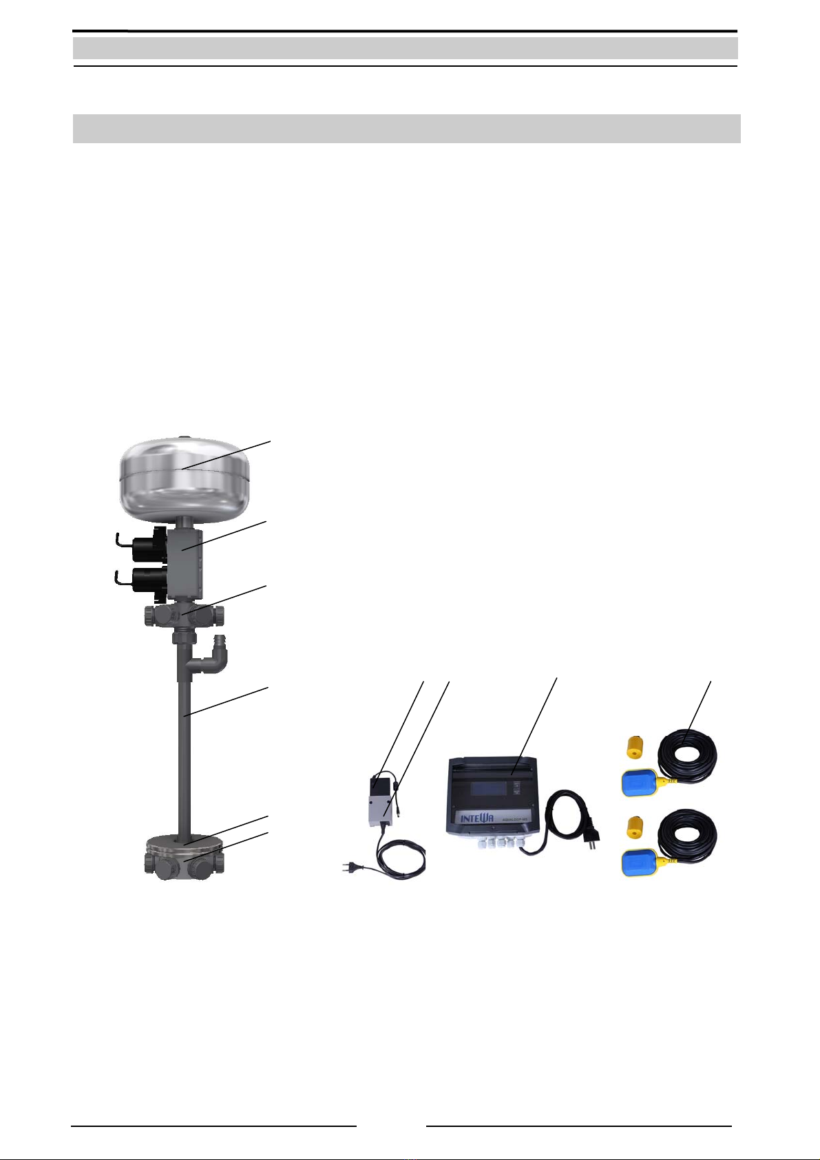
4.Scope of delivery ................................................................................................................................................................................4
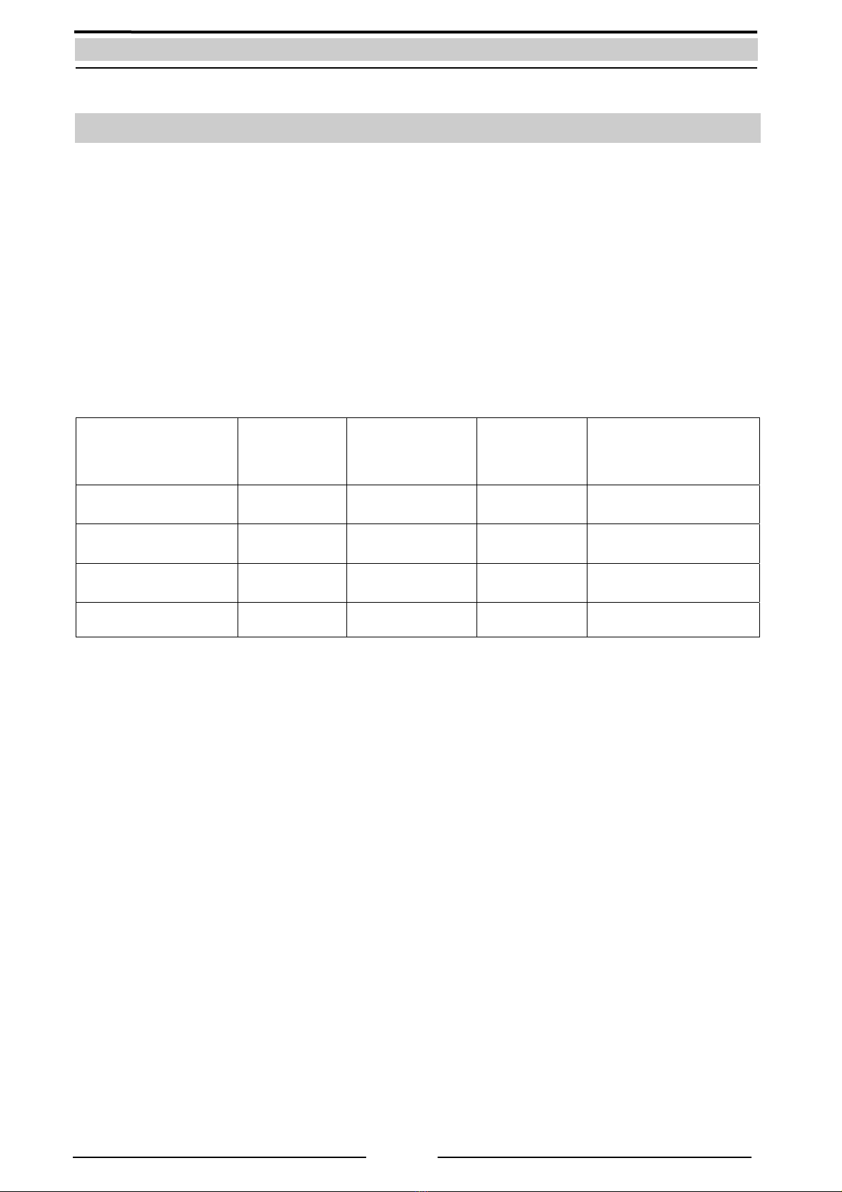
5.Technical data......................................................................................................................................................................................5
6.Instructions for controller................................................................................................................................................................7
6.1Electronic connections...........................................................................................................................................................7
6.2Operation mode display ........................................................................................................................................................ 9
6.3Menu overview ........................................................................................................................................................................10
6.3.1Menu settings and description .............................................................................................................................14
Menu 1: Number of membranes ....................................................................................................................14
Menu 2:Suction overflow.................................................................................................................................14
Menu 3:Sludge pump (optional) ...................................................................................................................15
Menu 4:Test menu..............................................................................................................................................15
Menu 5:Status overview...................................................................................................................................15
Menu 6:Setting time ..........................................................................................................................................16
Menu 7/8:Start time T1 and T2..........................................................................................................................16
Menu 9:Number of pump intervals A1/A2.................................................................................................16
Menu 10:Blower times and intervals ..............................................................................................................17
Menu 11:Chemical cleaning..............................................................................................................................17
6.5Installing controller and switching power supply bracket........................................................................................18
7Instructions for membrane station..............................................................................................................................................19
7.1Installing the membrane station........................................................................................................................................20
8.System start-up process..................................................................................................................................................................21
9.Self-help in case of failure...............................................................................................................................................................24
10.Maintenance and cleaning.............................................................................................................................................................25
10.1Chemical cleaning of AQUALOOP Membrane station................................................................................................25
10.2Cleaning solution ....................................................................................................................................................................27
11.Spare parts...........................................................................................................................................................................................27
12.Optional accessory............................................................................................................................................................................27
13.Warranty / Contact............................................................................................................................................................................28

2
1. Introduction and general instructions
AQUALOOP components are designed for water treatment / sanitation of wastewater. The following types
of raw water can be treated and sanitised with AQUALOOP:
-Clear water
-Surface and ground water
-Clear discharge water
-Grey water
Five AQUALOOP components are combined and dimensioned depending on the existing input water
quality or use.
The updated application range of all AQUALOOP components, along with their application examples, and
the operational dimensioning of each AQUALOOP component related to treatment, water quality and
required tank volume for the bioreactor and clear water tank, can be found at:
http://www.intewa.de/en/products/aqualoop/technology/dimensioning/
General background knowledge for water treatment and grey water utilization can be found at:
http://wiki.intewa.net/index.php/Wasseraufbereitung_und_Grauwassernutzung/en
This manual describes the assembly, settings and start-up procedure of the membrane assembly, which is
the basis of each application.
Fig.: AQUALOOP components

3
2. Safety instructions
This installation and operating manual of this device is to be read carefully before installation. The
specified instructions are to be followed exactly otherwise any respective warranty claim may be voided.
This also applies to any separate modifications made to the mechanical and electrical components.
The electronic housing of the current-carrying components may only be opened by a
certified electrician or approved installer.
The electrical circuit used for the system must be secured by a circuit breaker (16 A). Likewise, an ELCB
(earth leakage circuit breaker), with the maximum operating current is to be inserted, if not already
present.
The owner/operator is responsible for compliance of safety and installation provisions.
3. Guidelines, testing, environment
All electric components design and construction, as well as the circuitry, comply with the basic safety and
health standards of EC guidelines for machines. This declaration of validity lapses with any modification of
electronic components not approved by us.
The components particularly fulfil the following specifications of EU guidelines:
EC guideline machines (89/392/EEC) as amended in 91/368/EEC
EC low voltage guideline (73/23/EEC)
EC guideline electromagnetic compatibility (89/336/EEC) as amended in
93/31/EEC
The conformity of components to the above E guidelines is confirmed by CE symbol.
Applied harmonised EU standards:
EN 60335-1: 1194/A1/A11/A12/A13/A14, EN 60335-2-41: 1996
Test symbol: DC switching power supply
Kindly recycle the packaging in an environment-friendly way.
Do not dispose of the electronic components in domestic trash! According to European
Guidelines 2002/96/EC on electronic and old electronic devices and their application in
European countries, components should be collected separately and disposed through
the use of environment-friendly recycling.

4
4. Scope of delivery
1. Permeate backflushing container
2. Pump unit with suction and backflushing pump incl. 2 O-Ring seals
3. Permeate - distribution nozzle incl. 5 pc. screw caps each with flat seal
4. Central aeration pipe with 2 pc. flat seals
5. 2 pc. stainless steel wheel weight
6. Aeration distribution nozzle incl. 5 pc. closing caps (each with flat seal)
7. DC switching power supply incl. network cable
8. DC switching power supply part - wall bracket
9. Controller with LCD Display incl. network cable
10. 2 pc. float switch (15 m) incl. counterweight
Fig.: Scope of delivery
3
5
6
7 8 9 10
4
1
2

5
5. Technical data
Controller:
Dimensions (H x W/(incl. AC switching power
supply) x T):
201 x 198 (329) x 110 mm
Mains supply central controller (230V-IN): 110 - 230 V AC / 50-60 Hz
AC switching power supply input: 110 - 230 V AC / 50-60 Hz (24 V DC, 4.0 A)
AC switching power supply output: 24 V DC, 4.0 A
Cable length of mains supply: 3 x 1.0 mm² x 1.5 m
Cable length of AC switching power supply: 3 x 0.75 mm² x 2.0 m
Power outputs:
-Blower (230V Air): 110 - 230 V AC / 50-60 Hz, max. 4 A
-Sludge pump (230V Sludge): 110 - 230 V AC / 50-60 Hz, max. 4 A
Low voltage outputs:
-Suction pump (Pump Suction): 24 V DC, max. 4 A
-Backflushing pump (Pump Backflush): 24 V DC, max. 4 A
-Blower (Air): 24 V DC, max. 4 A (alternative )
Signal inputs:
-Bioreactor MIN (BR min): Floating switch, normally open contact
-Clear water tank MAX (CL max): Floating switch , normally open contact
-Clear water tank MIN (CL min): Pot, free contact (alternative)
Potential-free signal output:
-Clear water tank MIN (CL min OUT): Signal of CL max
Signal inputs:
-Pressure sensor Membrane hub (ADr): 4 … 20 mA
-Pressure sensor blower (ADg): 4 … 20 mA
Programmed connection: 6 pol., RM 2.53
Protection type: IP54
Float switch:
Function: Normally open contact (MIN = closed contact)
Cable length x Diameter: 15 m x Ø8 mm, 2 x 0.75mm²
Protection type: IP68
Membrane station:
Dimension (Ø x H): max. Ø 504 x 833 mm (with max. mounting)
Permeate distribution connection: lateral: 6 x 1“ AG; top: 1“ IG; bottom: 1 ½“ AG
Aeration distribution connection: Lateral: 6 x 1“ AG; top 1 ½“ AG
Central blower connection: Nozzle, Ø 25 mm
Backflushing container connection: ¾“ AG
Volume flow rate: max. 10 l/min
Pumping height: l max. 0,55m
Pump cable 2 x 0.75mm² x Ø 6mm, 3 m
Protection type of pump: IP68
Total weight (total/gross): 11.0 kg / 12.5 kg

6
Fig.: Dimensions of controller with DC switching power supply (Front and top view)
Fig. Dimensions of Membrane station (lateral and top view)

7
6. Instructions for controller
6.1 Electronic connections
Fig.: Electrical connections of control board and assigning cable routings
((cable bridge)

8
Item Connection Description Connecting contact/Function
1 ADr Pump Analogue pressure sensor for suction
and backflushing pump monitoring
Sig = green
GND = gray
Ub + = brown
2 ADg Air Analogue pressure sensor,
for monitoring blower
Sig = green
GND = gray
Ub + = brown
3 Float Sw
BR min
Float switch in bioreactor for minimum
water level
Pot. free contact, normally open
contact, no polarity
4 Float Sw
CL max
Float switch in clear water tank for
maximum water level
Pot. free contact, normally open
contact, no polarity
5 Float –Sw
CL min
No function --
6 Float –Sw
CL min out
No function --
7 Pump
Suction
24 V DC suction pump for filtration
process
GND = blue
+ = brown
8 Pump
Backflush
24 V DC backflushing pump
For cleaning process
GND = blue
+ = brown
9 Air
Only for use with a 24 Volt DC blower
(alternative to 230V blower)
GND = blue
+ = brown
10 230V- Air
230 V AC / 50 Hz blower PE = Green/yellow
N = blue
L = brown
11 230V-Sludge Sludge pump 230 V AC / 50 Hz
(Optional)
PE = Green/yellow
N = blue
L = brown
12 230V-IN Mains voltage supply
110- 230 V AC / 50 Hz
PE = Green/yellow
N = blue
L = brown
13 24 V DC-IN 24 V DC switching power supply, Stereo jack
Ø5.5mm, Centre positive
14 Cable bridge For activation of rechargeable battery
and switching power supply
(install cable bridge while start-up
installation)
4-pin plug ,
reverse-polarity protected
15 9V
rechargeable
battery
9 V battery, 200 mA, NIMH
Attention:
Only a rechargeable battery must be
used when changing the internal
battery!
Pay attention to polarity while
changing
16 6-pin 6-pin programmed connection
(for update programming)
Pay attention to polarity
17 DIL DIL switch
Factory setting 1 = ON
Factory setting 2 = OFFN
1=ON : Alarm* with battery operation
ON
1=OFF : Alarm with battery operation
OFF
2=ON /Off: without function
* A short beep sounds at an interval of 5
seconds indicating the battery alone is being
used!!
Tab.: Connection description of control board

9
6.2 Operation mode display
With different applications, one differentiates between two operating modes:
•Aeration / treatment mode
•Filtration / Pump cycle mode
The biological treatment is done in the aeration mode. Aeration mode does not run permanently, but is
run at intervals to save energy. The exact functioning is set by the controller. If aeration is not required (for
instance, with rainwater treatment) then the ventilation parameter is set (Air ON/OFF = 0/0).
The biologically treated water is filtered via membranes in the filtration mode and routed to the clear water
tank. The filtration start time (T1/T2) and filtration duration (A1/A2) can also be separately adjusted.
Neither aeration nor filtration operations occur in pause mode.
Application Filtration type Aeration setting
Pump cycles
setting value
Average flow rate
(each membrane and
day)
Clear water
sterilization
Direct filtration
BOD < 5 mg/l Air ON/OFF = 0/0 A1/ A2= 20/25 4 l/min / 1600 l/d
Surface ground water
(Rainwater)
Direct filtration
BOD < 25 mg/l Air ON/OFF =1/15 A1/ A2= 18/20 2.5 l/min / 800 l/d
Clear discharged
water
Direct filtration
BOD < 25 mg/l Air ON/OFF = 1/15 A1/ A2= 10/18 2-2.5 l/min/ 800 l/d
Gray water recycling MBR Filtration
BOD <200 mg/l Air ON/OFF = 5/10 A1/ A2= 5 / 9 1-1.5 l/min / 300 l/d
Tab.: Parameter examples for various applications

10
6.3 Menu overview
Menu1:
Change number of MEM
NEXT: MEM= 1
ENTER: Set
Menu2:
Change SO= 0
NEXT: next week
ENTER: Set
Menu2:
SO old= 0 new= 0
NEXT: exit, no change
ENTER: confirm
Menu2:
Change SO= 1
NEXT: nextweek
ENTER: Set
NEXT
Menu1:
Number of MEM=1
NEXT: to next menu
ENTER: to change MEM
NEXT
NEXT
NEXT
Menu2:
Suction Overfl. SO=0
NEXT: to next menu
ENTER: change SO
14: 22:08h / A= 4 / 9
T1=05:00h / T2=16:00h
Air ON/OFF
BRmin + / CLmax -
Menu1:
Change number of MEM
NEXT: MEM=2
ENTER: Set
NEXT
NEXT
NEXT
ENTER ENTER
ENTER ENTER ENTER
Key
:
Infinite loop up until a selection
is made with ENTER.
NEXT
NEXT
Key
:
Return to operation
mode display
.
Menu2:
SO old= 0 new= 1
NEXT: exit, no change
ENTER: confirm
ENTER ENTER
Menu3:
Change SP= 0
NEXT: next week
ENTER: Set
Menu3:
SP old= 0 new= 0
NEXT: exit, no change
ENTER: confirm
Menu3:
Change SP= 1
NEXT: nextweek
ENTER: Set
NEXT
Menu3:
Sludge pump SP
NEXT: to next menu
ENTER: change SO
ENTER ENTER
Menu3:
SP old= 0 new= 1
NEXT: exit, no change
ENTER: confirm
ENTER ENTER

11
ENTER
NEXT
ENTER
NEXT
NEXT
NEXT
NEXT
NEXT
ENTER
ENTER
ENTER
ENTER
ENTER
NEXT
ENTER
ENTER
NEXT
NEXT
Menu4:
Testmode
Next: to next test
ENTER: for Air ON
Menu4: Test Air ON
P(ADg):-1.200bar
Autostop: 5:59 min
Stop with ENTER/Exit
Menu4:
Testmode
Next: to next menu
ENTER: for Testmode
NEXT
NEXT
ENTER
Menu4: Sludge pump
Autostop: 5:59 min
Stop with ENTER/Exit
Menu4:
Testmode
Next: to next test
ENTER: for Suction ON
Menu4:
Testmode
Next: to next test
ENTER: Backflash ON
Menu4: Test Suction
P(ADr):-1.200bar
Autostop: 5:59 min
Stop with ENTER/Exit
Menu4: Test Backflush
P(ADr):-1.200bar
Autostop: 5:59 min
Stop with ENTER/Exit
NEXT
NEXT
NEXT
ENTER
Menu4:
Testmode
Next: to next menu
ENTER: Sludge pump ON
ENTER
NEXT
ENTER
NEXT
ENTER
-----Status 1 -----
MEM : 1
Air ON/OFF : 5/10min
Overflow : 0 week
Menu5:
Status overview
Next: to next menu
ENTER: for status
-----Status 2 -----
SLP : 0 / 15
P(ADr) :-1.200bar
P(ADr) :-1.200bar
-----Status 3 -----
Supply : 23.3 V
9V-Accu : 9.55V -L-
Firmware : GWA2.10
-----Status 4 -----
Supply failures : 11
During pumping : 0

12
Menu6:
Change hour
Next: >09<:26:00h
ENTER: set hour
Menu6:
Change minute
Next: 09:>26<:00h
ENTER: set minute
Menu6
Set actual time
Next: exit menu
ENTER: change time
NEXT
Menu7:
Change hour for T1
Next: >09<:26:00h
ENTER: set hour T1
Menu7:
Change minute for T1
Next: 09:>26<:00h
ENTER: set minute T1
Menu7
Setstart time T1
Next: exit menu
ENTER: change time
Menu8:
Change hour T2
Next: >09<:26:00h
ENTER: set hour T2
Menu8:
Change minute T2
Next: 09:>26<:00h
ENTER: set minute T2
Menu8
Setstart time T2
Next: exit menu
ENTER: change time
NEXT
Menu9:
Change A1
Next: > 4< / 4
ENTER: set A1
Menu9:
Change A2
Next: 4 / > 4<
ENTER: set A2
Menu9
Change A1/A2 suction
Next: exit menu
ENTER: change A1/A2
NEXT
ENTER ENTER ENTER
Menu6:
Change hour
Next: >10<:26:00h
ENTER: set hour
Menu6:
Change minute
Next: 09:>27<:00h
ENTER: set minute
NEXT
NEXT
NEXT
NEXT
ENTER
ENTER
ENTER
Setting process as in
Menu 6
Setting process as in
Menu 6
ENTER ENTER
ENTER ENTER ENTER
Setting process as in
Menu 6
Setting process as in
Menu 6
NEXT
ENTER ENTER ENTER
Menu10:
Change AIR ON
Next: >05< / 10
ENTER: set minute
Menu10:
Change AIR OFF
Next: 05 / >10<
ENTER: set minute
Menu10
Set time Air ON/OFF
Next: exit menu
ENTER: change time
ENTER ENTER ENTER
Setting process as in
Menu 6
Setting process as in
Menu 6
Setting process as in
Menu 6
Setting process as in
Menu 6
NEXT
NEXT
Menu11:
Chemical cleaning
Next: next menu
ENTER: start clean.
NEXT
See under chapter 10.1
ENTER

13
Operating mode display: Aeration cycle/Rest cycle
Operation display: Pump cycle T1 or T2 active
Operation display: Siphon or sludge pump mode
Operation display: Emergency mode (battery)
If no AC switching power supply is connected or following a power failure:
Instruction:
If there is a power breakout an electrical short circuit of the suction- or back flushing pump during the test
mode, the pumps and blower will stop operating. The display continues to run via the built-in 9V battery.
The parameters are thereby secured as the timer will continue to operate.
T
ime
Start time
- Pump cycle 1
Status display
-Aeration ON/OFF
Bioreactor
MIN Water level
-BRmin + (full)
-BRmin - (empty)
Number of pump cycle
Suction A1/A2
Start time
- Pump cycle T2
Clear water tank
MAX Water level
-CLmax + (full)
-CLmax - (empty)
Current
Pump cycle A
no display in
aeration mode
14: 22:08h / A= 4 / 9
T1=05:00h / T2=16:00h
Air ON /
BRmin + / CLmax -
16: 05:00h / A= 4 / 9
T1=05:00h / T2=16:00h
Break / A1=2
BRmin + / CLmax -
---- Attention ----
system runs on accu
all actions disabled
9V-Accu: 9.47V
14: 22:08h / A= 4 / 9
T1=05:00h / T2=16:00h
SO = ON (no suction)
BRmin + / CLmax -
Status display
-SO = ON
-SLP=ON/OFF
Status display
-Pause (Break)
-Suction (Suction)
-Backflushing (back
flush

14
6.3.1 Menu settings and description
Any menu can be retrieved by selecting NEXT on the operation display. One is directed to respective
menu settings by selecting ENTER. After leaving the menu setting, the display reverts back to the
standard operation display screen.
Generally, inputs or settings are displayed in addition to NEXT and ENTER.
If there is no input within 6 minutes in a menu mode, then the display automatically switches back to the
standard operation mode display.
Each menu setting must be set to the respective position the first time the controller is used. Any
adjustments are permanently stored in the internal memory, and can be overwritten at any time.
RESET Function / Factory settings:
The device can be reset to factory settings by the simultaneous pressing of both the NEXT and ENTER
buttons (for approx. 5 s)
1. Time: 12:00:00 hrs
2. Number of membranes: MEM = 1
3. Start time T1: T1 = 04:00 hrs
4. Start time T2: T2 = 16:00 hrs
5. Pump cycles: A1/A2 = 4 / 9
6. Blower time: Air ON / Air OFF = 5 / 10 (min/min)
7. Suction overflow: SO=0 week
8. Sludge pump: SLP/t=0 /0 (Weeks/min)
Menu 1: Number of membranes
(MEM = 1 to 6)
With this setting, the number of installed membranes is confirmed. This has reference to the
best setting for suction pump performance in the filtration process.
Note: MEM can always be modified even while flushing/backflushing is in progress.
Menu 2: Suction overflow
(Suction Overflow SO = 0 to 4)
This setting determines how many weeks shall pass before the pump will automatically enforce
a controlled overflow of the bioreactor tank.
With this function, through the AQUALOOP pre-filter, the sediment at the bottom of the tank is
siphoned out via the suction overflow. As the water level rises, the surface contaminants are
sucked out through the overflow skimmers.
•SO week = 0: Not operating.
•SO week = 1 to 4: Suction overflow after first, second, third or every fourth week. (The
aeration Air ON/OFF further runs in normal rhythm.)

15
Menu 3: Sludge pump (optional)
(Sludge pump SLP=0 to 9, t=0 to 60min)
This setting determines the weekly cycle of sludge pumping and the duration of the pumping.
Note: This function is crucial only for MBR applications where solid material content must be
minimised in the Bioreactor (for background knowledge Link Chap. 1). This function is not
required for other applications. In these other cases the sludge pump feature is deactivated on
the controller. (SLP=0, corresponds to factory settings)
•SLP = 0 (Weeks)/ t=0 min The sludge pump is not activated with this setting
•SLP = 1 to 9 (Weeks): The pump frequency is set from 1 to 9 weeks for 24h with this
setting. Then the sludge pump starts at specified period t. Aeration runs at the same
time. If the pump runtime is interpreted by "BR min – ", it restarts with "BR min + ". This
mode is left if the sludge pump has worked for the entire running period t.
Recommendation: The running time t should be selected in such a way so that the
pump pumps out at least half the bioreactor volume.
Menu 4: Test menu
(Test menu for blower, suction pump, back flushing pump and sludge pump)
The blower (air), suction pump (suction pump) back flushing pump (back flush pump) and
sludge pump (sludge pump) can be separately controlled and tested via the test menu. The
test mode can be terminated at anytime with NEXT/ENTER. The time until automatic stop (max.
6 min) is shown on the display by a count-down stopwatch.
A test can be performed anytime, however there must be sufficient water for pump activation
(BR min +). If the water level falls below minimum, (BR min -) then the display shows that a
pump test is not possible.
Menu 5: Status overview
(Status Overview: Status 1 to 4)
The overview mode can be viewed at anytime. All other activities, such as aeration mode and
pump frequency, continue in the background. All current settings and operating status can be
viewed in this mode.
Status 1:
Number of membranes: MEM : 1
Aeration settings: AIR ON/OFF : 5 / 10 min
Suction overflow: Overflow : 1 week
Status 2:
Sludge pump: SLP : 5 / 20
Pressure sensor Pumps: P(ADr) : -1,200 bar
Pressure sensor blower: P(ADg) : -1,200 bar

16
Status 3:
Voltage power supply : Supply : 23,3 V
Battery voltage: 9V battery : 9,55 V -L-
Software version: Firmware : GWA2.10
Status 4:
Number of current interruptions in 24 V supply): Supply : 11
Number of current interruptions (24 V) with pump frequency: during pumping: 0
Menu 6: Setting time
The set time is critical for pump start times T1 and T2. The clock will operate for approx. 5 hours
on battery life in the event of a power failure. Thereafter, the capacity of battery is exhausted
(Display switches off). When the external AC switching power supply comes on again after
battery ran off, the clock must be re-set in order to correctly restart the cycle times T1 and T2
corresponding to real time.
Note: A started pumping cycle is terminated independent of the corrected time.
The time can be adjusted at any time.
Menu 7/8: Start time T1 and T2
(Starting time point T1 and T2 for pumping cycle)
Note for selection of start time points T1 and T2:
The pump starting times T1 and T2 are primarily set according to the times of input water (for
instance, grey water) being processed in the bioreactor with MBR Filtration. There must be at
least 6 hours of biological treatment between grey water intake and the pump starting. This
treatment time is required to ensure a long life of the membrane filter.
Example: If the taking of showers is scheduled mostly in the morning between 7:00-8:00 hrs,
then the pump cycle T1 must be finished before 7:00 hrs.
Shorter times for direct filtration are possible up to direct filtration at incoming times.
It is important that a pump cycle run time is not overlapped with next start time. If this is the
case then the second timed start will not occur as required.
Menu 9: Number of pump intervals A1/A2
The numbers A1 and A2 determine how many pump intervals A (each with 15min run time/15s
backflushing) must be passed in pump cycles T1 and T2.
The number of pump intervals is adjustable from A=1 to A= 25.

17
The pump cycle starts when the starting time point T1 or T2 is reached. The first pump interval
begins after a 5 minute rest phase. The potentially connected blower is deactivated during the
suction operation. In conjunction with back flushing, it is then activated to support back
flushing cleaning process with air.
There is a temporary aeration after every fourth pump interval, followed by a 5 minute rest
phase. Then it is continued forth with the next pump block. The pump cycle is terminated
when all pump intervals have been performed.
Fig.: Example of a pump cycle with A = 5
The pump cycle can be interrupted by the float switch "BR min –" (when the water level for the
membrane falls below the minimum allowed level) and "CL max +" (when the clear water tank is
full).
Menu 10: Blower times and intervals
The blower run time (Air ON) and blower pause time (Air OFF) can be set within the range of 1 to
15 min. The set blower operation is performed in total aeration mode and interrupted only by
the pump cycle. The aeration always starts with "Air ON" after any adjustments to the time have
been made.
Setting example for various aeration types:
Timed aeration: Air ON/Off = 5 / 10 (5 Minutes aeration, 10 Minutes Pause)
Continuous aeration: Air ON/OFF = 15 / 0
Deactivated aeration Air ON/OFF = 0 / 0
Menu 11: Chemical cleaning
See under section "Maintenance and chemical cleaning"

18
6.5 Installing controller and switching power supply bracket
The controller housing and power supply brackets are mounted
to the wall next to each other.
Note: Pay attention that there is space to open the housing lid
above the housing and a place for cable routings below the
housing installation space (each at least 190 mm).
Fig.: Drilled hole distances of controller housing and DC switching power supply brackets

19
7 Instructions for membrane station
Fig.: Overview of Membrane station
1. Backflushing container
2. Backflushing pump
3. Suction pump
4. Permeate distributor
5. aeration pipe
6. Membrane cartridge
7. Wheel weight
8. aeration distributor nozzle
Minimum water level (BRmin)
This manual suits for next models
1
Table of contents