INTO DAALDEROP HRU ECO 350 User manual

Itho Daalderop
HRU ECO 350
User manual
A

Original document.

3
Foreword
This manual is intended for the user of the appliance
and contains important information on the use,
maintenance and malfunction of the appliance.
The installer is responsible for the installation and
commissioning of the unit.
The following definitions are used in this manual to
draw attention to dangers, instructions or directions
relating to persons, product, installation and/or
environment.
Itho Daalderop reserves the right to change
products and manuals without prior notice.
Due to our continuous process of improving our products,
this document may differ from the product delivered to
you. You can download the latest version of this manual
from our website.
Although this manual has been compiled with the
utmost care, no rights can be derived from it.
Tip
Don't forget to register the product via the website of
Itho Daalderop!
Tip
Indications that may be relevant to the installation,
operation, operation or maintenance of the product,
not related to injury to persons or damage to
property.
Note
Instruction relevant to the installation, operation,
operation or maintenance of the product. Ignoring this
instruction may cause minor material damage to the
product, installation or environment.
ä Attention
!
Instruction relevant to the installation, operation,
operation or maintenance of the product. Ignoring
this instruction may cause minor bodily injury to
persons and/or serious material damage to the
product, installation or environment.
ä
Warning!
Indicates a risk of personal injury to persons and/or
serious damage to the product, installation or
surroundings.
Tip
Keep the manual in the appropriate place in the
ventilation unit.

4
Content
1.
Safety and regulations 5
1.1.
Security 5
2.
Product information 7
2.1.
Living comfort and energy savings 7
2.2.
Heat recovery 7
2.3.
Filters 8
2.4.
Schemes 8
2.5.
Grids 11
2.6.
Application in a new home 11
2.7.
Product card information 12
2.8.
Accessories 13
2.9.
Recycle 13
3.
Operation 14
3.1.
Ventilation modes 14
3.2.
Controls 15
3.3.
Sensors 16
3.4.
Subscribing and unsubscribing wireless 16
controls and sensors
4.
Inspection and maintenance 17
4.1.
Inspection and maintenance schedule 17
4.2.
Inspection, cleaning/replacing 18
filters
4.3.
Cleaning mosquito filter 19
4.4.
Inspection/Cleaning valves 20
4.5.
Maintenance wireless control 20
5.
Malfunctions 21
6.
Warranty 26
7.
Statements 27

5
1.
Safety and regulations
1.1.
Security
●Work on the ventilation
system may only be carried
out by approved installers (1) in
accordance with the
instructions in the manual.
Only accessories and parts
as prescribed by the
manufacturer may be used.
●Do not use the product for
purposes other than those
for which it is intended, as
described in this manual.
●Handle electrical
appliances with care:
-
Never touch the device with
wet hands.
-
Never touch the device
when you are barefoot.
●This product and/or system
may be operated by children
aged 8 years and over and by
persons with reduced
physical, sensory or mental
capabilities or lack of
experience and knowledge if
they are supervised or
instructed in its safe use and
are aware of the dangers of
the product and/or system.
●Cleaning and maintenance by
the user must not be carried
out by children or by persons
with reduced physical,
sensory or mental capabilities
or a lack of experience and
knowledge without
supervision.
●Prevent children from playing
with the product and/or
system.
●Do not use the product in the
presence of flammable or
volatile substances such as
alcohol, insecticides, petrol,
etc.

6
●Safety instructions must be
followed to prevent physical
injury and/or damage to the
product.
●Maintenance and cleaning
may only be carried out after
the appliance has been de-
energized.
●The product contains rotating
parts. Therefore, after
disconnecting the product
from the power supply, wait at
least 10 seconds before
opening or touching the
product, because these parts
will continue to rotate for
some time.
●Secure the system against
unintentional reactivation.
●Maintenance instructions must
be followed to prevent damage
and excessive wear and tear.
●The product must not be
modified.
●The product is only suitable
for a 230 V 50 Hz AC
system.
●Make sure that the electrical
system to which the product
is to be connected meets the
required conditions.
●Do not expose the product to
weather conditions.
●Do not place any objects
on the device.
●Regularly inspect the product
for defects. In the event of
defects, switch off the product
and contact your installer or
the Itho Daalderop service
department immediately.
●Switch the product off
when:
-
The product does not
function properly.
-
You want to clean the
outside of the product.
●
Take care not to damage
the electrical circuit.
●Do not use the appliance to
vacuum water boilers, heating
systems, etc.
●Make sure that the appliance
drains into a drain thatis
suitable and laid for this
purpose and that drains to the
outside.
●Keep valves and grids free
and clean.
1) A qualified installer is an installer working for a central heating
or mechanical installation company registered with the
Chamber of Commerce and included in the SEI recognition
register (Stichting Erkenning Installatiebedrijven) orwho has
a Sterkin recognition.

7
2.
Product information
2.1.
Living comfort and energy savings
Living comfort and energy savings are becoming
increasingly important in housing construction.
Nowadays, homes are increasingly insulated, but
unfortunately good insulation often comes at the
expense of the indoor climate.
Without good ventilation, moisture, moulds and dust
mites can escape, and the air in the house can quickly
feel 'stuffy' due to an increasing concentration of CO2
(carbon dioxide). Itho Daalderop installs equipment that
regulates the indoor climate and takes into account the
requirements for comfort and energy consumption in
homes.
One of these advanced devices is the Itho
Daalderop ventilation system HRU ECO 350.
The HRU ECO 350 is a balanced ventilation system
with heat recovery. The ventilation unit is equipped with
two fans; one for the return air and one for the supply
air.
The ventilation unit ventilates several rooms in the
house. By means of ducts, the kitchen, the bathroom, the
toilet and possibly the indoor storage/laundry room (the
'wet rooms') are connected to the ventilation unit for the
removal of polluted/humid air.
The living room, the bedrooms and possibly the
corridor/hallway are also connected to the ventilation unit
by means of ducts, but fresh air is brought in here.
To ensure good air distribution, the supply and return
points in the rooms to be ventilated are fitted with
extraction valves and supply grilles respectively.
In this way, the HRU ECO 350 helps to reduce the
humidity in your bathroom, refresh the toilet and drive
cooking odours out of the kitchen.
2.2.
Heat recovery
Before the polluted air is removed to the outside, it is
filtered and passed through the heat exchanger. The
fresh outside air is also filtered and passed through the
heat exchanger before it is brought into the house. In the
heat exchanger, the two air flows are routed past each
other (i.e. they are not mixed with each other). As a
result, the heat
of the exhaust air transferred to the fresh supply air, so
that this energy is not lost.
Heat recovery takes place with a very high efficiency.
On average, about 90% of the heat removed is
returned to the home. So there is only about 10% heat
loss.

8
ä
Warning!
The HRU ECO 350 must be fitted with the
appropriate ID filters at all times! Without filters, the
unit can suffer irreparable damage.
of potmeters on the unit. In addition, the ventilation unit
has some automatic controls that operate continuously
in the background.
2.3.
Filters
The HRU ECO 350 has two filters, one for each air flow.
Both filters are placed in the ventilation unit in such a way
that they protect the exchanger from contamination. In
addition, the filter in the air supply also protects the user
against dust and other contaminants in the sucked in
outside air.
There are different types of filters:
●Filter G3.
This filter is supplied as standard with the appliance
and is very suitable as a 'building material filter' in the
first period after delivery of the new home. After
about three months the filter has to be replaced by a
G4 or F7 filter.
●Filter G4.
This coarse filter is mainly used to filter relatively
large dust particles from the air. This mainly
protects the heat exchanger against penetrating
dirt.
●Filter F7.
In addition to the coarser dust particles, this fine
filter also retains finer dust particles (fine dust,
pollen). Especially people with allergy
complaints, who are sensitive to this, can benefit
from this.
Over time, the filters will become dirty, which will reduce
the capacity of the ventilation unit. It is therefore
necessary that the filters are cleaned according to the
instructions and eventually replaced.
2.4.
Schemes
The HRU ECO 350 has a 3-position control as standard,
whereby the ventilation flow in the low and high
positions can be infinitely adjusted by means of
Note
Despite the heat exchange, in which the fresh outside
air is pre-heated, the balanced ventilation system
should not be regarded as a heating system. It is a
ventilation system that contributes to a comfortable
and healthy living environment in the home.

9
2.4.1.
Summer bypass scheme
The purpose of the summer bypass control is
to ventilate the house with less, or completely
without heat transfer.
The Itho Daalderop heat recovery unit HRU
ECO 350 is supplied as standard with a
bypass valve that is 100% integrated in the
unit. This valve works fully automatic. The
bypass ensures that the sucked in outside air
is guided around the exchanger. The return air
still passes through the exchanger.
This automatic control will be activated mainly at
night, in summer. The outside air is then usually
cooler than the warm inside air.
2.4.2.
Frost protection
The HRU ECO 350 is equipped with frost
protection as standard. The frost protection
consists of a unique frost valve that is integrated
in the top of the unit. This valve works fully
automatic and prevents the ventilation unit from
freezing internally during winter days.
The air extracted from the house (return
air) emits heat to the fresh air drawn in
from outside.
This cools the return air in the heat exchanger. If
the temperature of the return air in the heat
exchanger gets too close to the freezing point,
the unit will open the frost valve at the top of the
unit and suck in warm room air. This warm room
air is mixed with the cold outside air.
At the same time, the supply fan turns faster so
that the amount of fresh outside air remains the
same. Because the fresh cold outside air is pre-
heated, the warm exhaust air from the house
does not have to heat up the cold freezing air as
much. The temperature of the return air in the
heat exchanger then remains safely above
freezing point.
Should the outside temperature drop even
further, the supply fan will turn softer to a
minimum in the end.
Note
The summer bypass control is not cooling, but it does
ensure that the house remains cool longer in the
summer night.
10
If the temperature drops any further, the drain fan will
run harder and the supply fan will continue to run at a
minimum. If the outside temperature becomes extremely
low, the supply fan will turn off, but the drain fan will
continue to operate. The frost valve will therefore be
closed.
After a certain period of time, the supply fan will start to
run at a minimum and the frost valve will be opened again
to check whether the danger of freezing has now
disappeared. If the outside temperature rises, the above
measures are carried out in reverse order until the danger
of freezing has passed. The resident 'always' determines
the discharge air quantity.
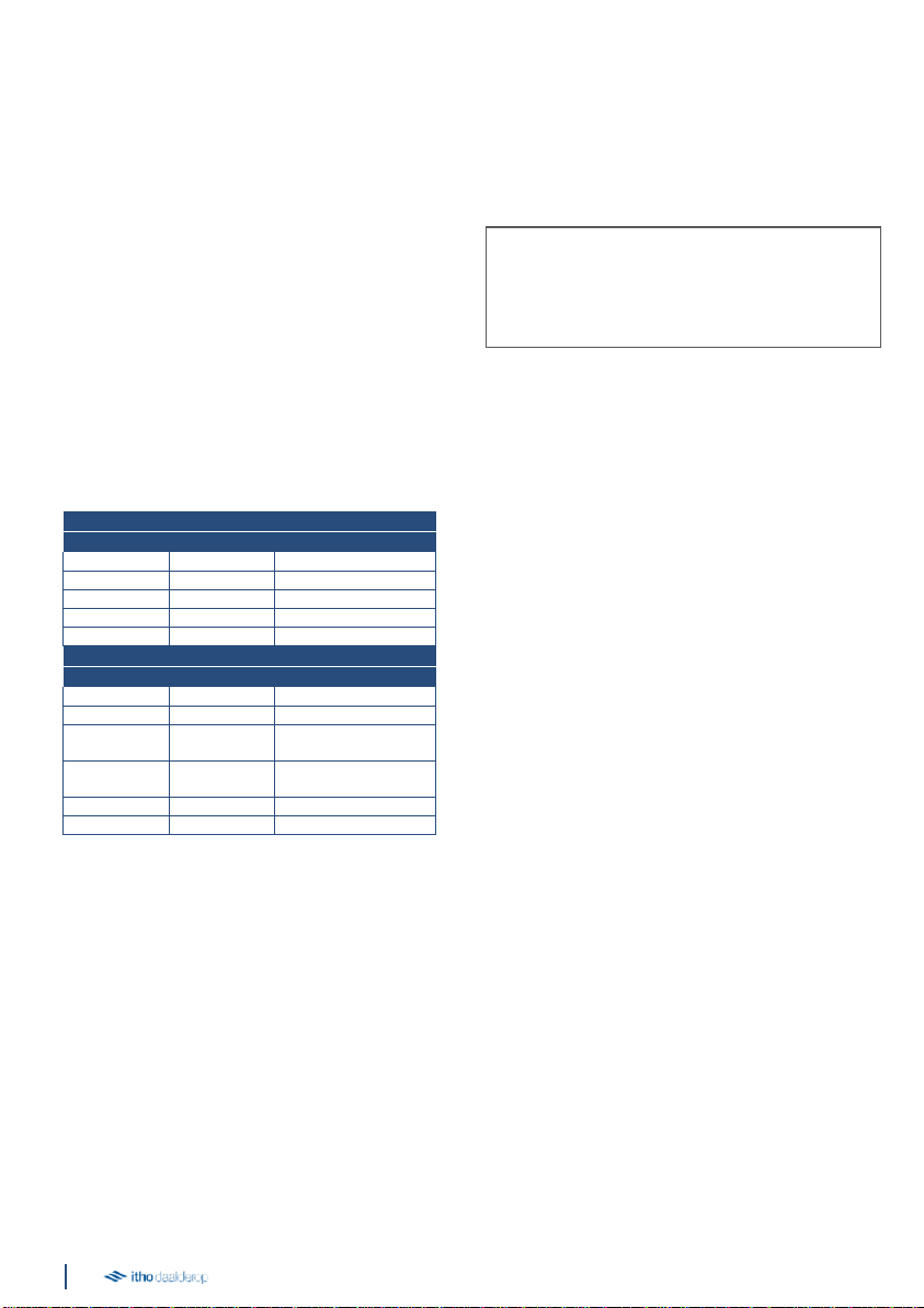
2.4.3.
Status LED
The appliance is equipped with a status LED. The status
LED can display the following messages:
Pattern
Function
Green
Orange
Flashes 1x/s
Flashes 1x/s
Identification
Flashes 1x/s
Login mode
Burns 6 s
Flashes 1x/s
Frost mode
Burns 5 s
Flashing 2x/s
Bypass mode
Brandt
Normal operation
Pattern
Function
Red
Orange
Flashes 1x/s
Flashes 1x/s
Error drain fan
Flashes 1x/s
Flashing 2x/s
Error supply fan
Flashing 2x/s
Flashing 2x/s
Sensor error
outlet temperature
Flashing 2x/s
Flashing 3x/s
Sensor error
supply temperature
Flashing 3x/s
Flashes 1x/s
Sensor error
Flashes 1x/s
Filter dirt
2.4.4.
Automatic ventilation based on CO2
measurement
A wireless CO2 sensor can be connected to the ventilation
unit.
For a healthy indoor climate and the prevention of a
'dull' house, it is important that it does not become too
high.
The controllable sensor can be mounted in any room
(except the bathroom), but preferably in living rooms
and/or bedrooms.
The controllable sensor measures what is happening in
the room. It translates the measured value into a
ventilation wish and
it communicates wirelessly to the ventilation unit to which
the sensor has been logged in. In this way, the
ventilation is continuously adjusted automatically and you
are assured of a good indoor climate in the most efficient
and energy-efficient way.
As soon as the weather has dropped sufficiently, the
capacity of the ventilation unit is automatically reduced.
2.4.5.
Automatic ventilation based on RH
measurement
A wireless RH sensor can be connected to the ventilation
unit.
For a healthy indoor climate and the prevention of damp
spots and moulds in the house, it is important that the
relative humidity does not remain too high for too long.
The controllable sensor can be mounted in any room,
but preferably in a room where a lot of moisture is
produced, such as a bathroom.
The controllable sensor measures the relative humidity
(RH) in the room. It translates this measured value into a
ventilation wish and communicates it wirelessly to the
ventilation unit on which the sensor is registered. In this
way, the ventilation is continuously adjusted
automatically and you are assured of a good indoor
climate in the most efficient and energy-efficient way.
As soon as the RH has fallen sufficiently, the
capacity is automatically reduced.
2.4.6.
Automatic ventilation based on
presence detection
A wireless PIR sensor can be connected to the
ventilation unit.
For a healthy indoor climate and toprevent dirty
odours in the house, it is important that sufficient
ventilation is provided in the presence of persons.
The sensor can be mounted in any room, for example in
the toilet or a bathroom with toilet.
Tip
It is possible to place several wireless sensors and
controls in the house, up to a maximum of 20
pieces.

11
The sensor detects presence (and absence) in the room
and communicates this wirelessly to the ventilation unit to
which it is logged on.
When the ventilation unit is in the Auto position, the
capacity is continuously adjusted automatically.
If the sensor detects movement, the ventilation is steered
to an increased capacity for a set period of time. If there is
permanent presence detection, the capacity will be further
increased. If the motion detector no longer detects
movement for a set period of time, the capacity is
automatically reduced again.
A unique feature of the climate thermostat is that it is
also suitable for controlling your Itho Daalderop
ventilation system (3). By connecting the ventilation unit
wirelessly to the thermostat, you can also control the
ventilation via the thermostat in addition to the wireless
controls and sensors.
1)
Function only available if the connected product supports
thefunctionality.
2)
Cooling via wireless OpenTherm® is not possible.
3)
Check the website to see which products are suitable for the
Spider Climate Thermostat.
2.4.8. Filter warning
The control of the ventilation unit keeps track of when
the filters need to be cleaned or replaced by means of
a counter. If a dirty filter is detected, the LED (4) on the
ventilation unit flashes orange.
2.4.7. Operation with the air conditioning
thermostat Spider
Schematic display connecting thermostat.
Legend
A Spider Climate Thermostat
B Boiler / heat pump
CCentral heating unit
D
Wireless control ventilation
E
Wireless sensor with control
The Spider Climate Thermostat is a climate thermostat
that regulates the temperature of the room in which it is
placed. In addition to a central heating boiler, the
thermostat is also suitable for controlling a heat pump
which, in addition to heating, can also cool the house
(1). The thermostat is connected OpenTherm® (wired
or wirelessly(2)) or On/Off (wirelessly only) tothe boiler or
heat pump (3).
1
Balance supply setting
2
Potmeter-High setting
3
Potmeter-Low setting
4
Status LED / Dirt filter indication
5
Communication connection
6
Dipswitch setting (VKK & AWW)
C
D
E
A
B
ä Attention
!
Control based on wireless sensors (CO2, RH and/or
PIR) only works if the ventilation unit is in
Auto/Auto night mode.
COM
CHP AWW
ON ON
1
2
3
4
5
6
Legend

12
Note
It is very important that you do not make any changes
to the setting of the gratings. This disrupts the proper
functioning of the entire ventilation system. Do not
exchange grilles and valves with each other.
indoor climate is achieved. For example, the air
extraction and the air supply are different in size for
each room. The extract and supply air grilles therefore
each have their own fixed position and setting.
2.4.9.
Filter warning CO2 sensor or RH
sensor
If the ventilation unit detects that the filter needs to be
cleaned or replaced, the unit sends a message to the
controllable CO2 sensor, and RH sensor (if connected). The
status LED on the sensor then flashes orange at 1 Hz.
After cleaning or replacing the filter, the counter must be
reset, see Resetting the Dirty Filter Indication on page 19.
2.4.10.
Filter warning Spider
climate thermostat
If the ventilation unit detects that the filter needs to be
cleaned or replaced, the unit sends a message to the
Spider air conditioning thermostat (if connected). The
display of the climate thermostat will show the message
Replace filter. The orange filter symbol flashes and the
ventilation symbol and the Service button illuminate
continuously. After cleaning or changing the filter, the
counter must be reset, see Resetting the dirt filter
indicator on page 19.
2.5.
Grids
The quantity of air to be extracted is regulated by law,
and the quantity of air to be blown in must be in balance
with this. In other words, as much air has to be extracted
as is supplied. The minimum air quantity per room is also
determined by law. The quantities are chosen in such a
way that no unnecessary energy is wasted and still an
optimum level of air quality is achieved.
2.6.
Application in a new home
Each new home contains a large amount of building
moisture, an average of around 4000 litres. This moisture
comes from wet building materials such as concrete,
cement, paint and glue. During construction, rain can also
make the building materials wet. The building moisture
disappears best by ventilating the house well and keeping
the temperature as constant as possible.
Dry-fire - not too fast.
By bringing heat into the house you stimulate the drying
process of the house, this is also called the drying of a
house. This drying must not be done too quickly, because
drying out too quickly results in a lot of damage (such as
shrinkage cracks). It is therefore important to pay a lot of
attention to dry firing. Keep in mind that this so-called dry
firing process can take up to six months. Set the heating
to 15 to 18°C, and when you are going to live there to 20
degrees. Do not turn up the heating, because if it
becomes too hot the materials dry too quickly and
damage may occur to the building structure.
Ventilation during dry firing.
During the drying process, good ventilation and
circulation of the air is indispensable. During the first
year, keep about 5 centimetres of space between the
walls and your furniture so that moisture can escape.
Open the windows for a while every day. In addition, the
(night) ventilation grilles should be permanently open and
always leave the mechanical ventilation system on, so
never pull the plug out of the socket. During the first few
months, set the mechanical ventilation to a high position
as much as possible.
This creates the best possible air circulation in the
home.
Energy bill.
Good and continuous ventilation is not only important for
our health, it is also an important weapon against
moisture problems in the home. With ventilation, heat is
lost. The process of dry-firing a new home also results in
higher energy consumption, which will result in a higher
energy bill.
ä Attention
!
If a dirty filter is detected, the resident also receives
a signal because the operation suddenly seems to
work the other way around: if you press the Low
mode button on the remote control, the ventilation
unit goes to High mode and if you press High mode,
the unit goes to Low mode.
Then check the LED on the ventilation unit. If it
flashes, the filter must be cleaned or replaced.
Note
It is advisable to check the LED on the
ventilation unit regularly.

13
2.7.
Product card information
Itho Daalderop
HRU ECO 350
Description
Symbol
Unit
Specific energy consumption class
—
—
A
Specific energy consumption, under moderate
climate conditions
SEC
kWh/(m2.a)
-39
Specific energy consumption, under warm
climate conditions
SEC
kWh/(m2.a)
-13
Specific energy consumption, under cold
climate conditions
SEC
kWh/(m2.a)
-82
Type of ventilation unit
VE
—
-
Residential ventilation unit
(RVE)
-
Two-way ventilation unit
(TVE)
Type of drive
—
—
Variable speed
Type of heat recovery system
HRS
—
Recuperative
Thermal efficiency of heat recovery
ƞt
%
94
Maximum flow rate
qmax
m3/h
350
Electrical input power of the fan drive,
at maximum flow rate
Pmax
W
154
Sound power level
LWA
dB
52
Reference flow rate
qref
m3/s
0,069
Reference pressure difference
ΔPref
Pa
50
Specific input power
SPI
W/(m3/h)
0,255
Ventilation control
—
—
Manual control (no DCV)
Control factor
CTRL
-
1
Indicated maximum percentages for internal leakage
for two-way ventilation units
—
%
2,0
Indicated maximum percentages for external leakage
for two-way ventilation units
—
%
3,0
Replace warning filter
—
—
on the unit
Instructions for pre-assembly/disassembly
—
—
www.ithodaalderop.nl
Annual electricity consumption
AEC
kWh
3,4
Annual heating savings, under temperate
climate conditions
AHS
kWh
47
Annual heating savings, under warm
climate conditions
AHS
kWh
21
Heating saved annually, under cold conditions
climate conditions
AHS
kWh
92
Specific precautions for assembly, installation or maintenance
Read the manual before installation
and use

14
2.8.
Accessories
Article no.
Type
Description
536-0124
RFT W
Wireless control switch with
three
modes and timer function.
(White)
536-0150
RFT CAR
Wireless RF control switch
with 2
modes, auto and timer function.
580-0230
HRS-3I C
Wired 3-position switch
for installation
04-00045
RFT-CO2 230V
RFT-CO2 sensor with
operation - 230 V powered
04-00046
RFT-RV BAT
RFT-RV sensor with control
- battery-powered
545-7550
RF-PIR BAT
RF-PIR presence sensor -
battery-powered
03-00062
Spider Base
Climate thermostat
545-1507
VKK
Ventilation Boiler Coupling
545-1508
VKK-HB
Ventilation Boiler Coupling HB
591-1070
FGD 180-50
Sound damping flexible
hose, Ø 180 mm, length 50 cm
591-1270
FGD 180-100
Sound damping flexible
hose, Ø 180 mm, length 100 cm
591-1050
FGD 152-50
Sound damping flexible
hose, Ø 152 mm, length 50 cm
591-1250
FGD 152-100
Sound damping flexible
hose, Ø 152 mm, length 100 cm
63-00004
OJ 600I
PureBlue Induct 600
air purifier
2.9.
Recycle
Durable materials have been used in the manufacture of
this product. This product must be disposed of
responsibly at the end of its life. The government can
provide you with information about this.
The packaging of the product is recyclable. These
materials must be disposed of responsibly and in
accordance with government regulations.
In order to draw attention to the obligation to dispose of
batteries and household electrical equipment separately,
the symbol of a crossed-out wheeled bin shall appear on
the product. This means that at the end of its service life,
the product must not be disposed of with ordinary
household waste. The product must be taken to a special
centre for separate collection in the municipality or to a
point of sale that provides this service.
Separate treatment of batteries and household
appliances avoids possible negative effects on the
environment and health caused by inappropriate
treatment. It ensures that the materials making up the
appliance can be recovered in order to achieve
significant savings in energy and raw materials.

15
Note
The timer function can be interrupted at any time by
pressing the low, high or automatic mode button.
3.
Operation
3.1.
Ventilation modes
The ventilation unit can be set to one of the following
positions as required:
●Position 1, low position: when one person is present
during the day or night or when nobody is present.
●Position 2, middle position: for day or night when
more than oneperson is present.
or
Auto mode, automatic mode; control based on
existing sensors (CO2, RH and/or PIR). The capacity
is automatically controlled between low and high
position.
●Stand 3, high level: for when cooking, showering or
bathing or when many people are present.
●Timer
The duration of the timer is determined as follows:
-
Press timer button once: 10 minutes high.
-
Press timer button twice: 20 minutes high.
-
Press timer button 3 times: 30 minutes high.
After the timer has elapsed, the unit will return to the last
mode selected before the timer was switched on, unless
this is the high mode. In this case, the unit switches to
low or automatic mode, whichever is selected last.
●Auto-night stand. The Auto-Night setting ensures
that the minimum ventilation setting is increased so
that sufficient ventilation is also provided at night.
You can use the Auto-Night setting when you go to
bed in the evening. Make sure that the window
grilles are open when using this mode.
To switch on the Auto-Night position, press the Auto-
button twice on the wireless control switch or
controllable sensor. The Auto-Night setting cannot be
set using the wired three-position switch.
Note
The current ventilation position can always be read on
the (optional) external CO2 sensor or RH sensor.
Note
If several controls are used, it may happen that the
ventilation position on the wired control switch does
not correspond to the current ventilation position
because the ventilation unit has been set to a
different position with a different control or sensor.
ä Attention
!
The Auto-Night mode is only available when one
CO2 sensor is used. If several CO2 sensors are used,
the ventilation in the bedrooms is automatically
adjusted and the Auto-Night mode is not required.
ä Attention
!
The Auto-Night mode does not switch off
automatically after a certain period of time. In the
morning you have to switch on Auto mode (or
another mode) yourself.

16
3.2.
Controls
1
2
3
RFT- CO 2
4
RFT - RV
5
6
Various positions are pre-programmed in the ventilation
unit. A number of control switches are available for
active tuning to the correct stand/ventilation capacity:
1.
Wireless control switch mer three positions and
timer function.
2.
Wireless control switch with two positions, an
automatic position and timer function.
3.
Wireless CO2 sensor with control - 230V powered.
4.
Wireless stainless steel sensor with control
- battery operated.
5.
Wired 3-position switch for installation.
6.
Spider Base, climate thermostat with three modes,
an automatic mode and a timer function. When a
Spider Connect system is installed; controllable via
the Spider climate thermostat.
A combination of the above possibilities.
You can register up to 20 wireless control switches
and/or sensors on an Itho Daalderop ventilation unit or
system.

17
3.3.
Sensors
The ventilation unit can be controlled by the following
available sensors:
●RFT-CO2 sensor including operation; 230V
●RFT-RV sensor with control - battery operated;
●RF-PIR BAT battery powered.
To enable or disable a remote sensor unit, see Enabling
or disabling wireless controls and sensors on page 16.
3.4.
Logging on and off of wireless
controls and sensors
3.4.1.
Sign in wireless controls
Preferably announce a wireless control switch in the
vicinity of the ventilation unit.
a)
Disconnect the power supply to the ventilation unit
by removing the plug from the wall socket.
b)
Wait at least 15 seconds.
c)
Power the ventilation unit by plugging the plug
back into the wall socket.
d)
Within two minutes after the ventilation unit has
been energised, press two diagonally placed
buttons on the control switch simultaneously.
The control switch is registered and the ventilation unit
briefly varies in speed to confirm the registration. The
ventilation unit is now ready to be operated using the
wireless control switch.
3.4.2.
Log off wireless controls
Preferably sign off a wireless control switch in the vicinity
of the ventilation unit.
a)
Disconnect the power supply to the ventilation unit
by removing the plug from the wall socket.
b)
Wait at least 15 seconds.
c)
Power the ventilation unit by plugging the plug
back into the wall socket.
d)
Press the four buttons of the control switch
simultaneously within two minutes after the
ventilation unit has been energised.
The ventilation unit no longer reacts to the wireless
control switch(s) and sensors. Unsubscribing
one control switch automatically reports all
wireless accessories.
3.4.3.
Sign up wireless sensors
Connect the remote sensor to the ventilation unit in the
following way:
a)
Disconnect the power supply to the ventilation unit
by removing the plug from the wall socket.
b)
Wait at least 15 seconds.
c)
Power the ventilation unit by plugging the plug
back into the wall socket.
d)
Make sure that a notification message is sent from
the sensor within two minutes after the ventilation
unit has been powered up. Please refer to the
documentation supplied with the sensorconcerned.
The sensor is logged on and the ventilation unit briefly
varies in speed to confirm the logging on. The ventilation
unit is now ready to respond to signals from the wireless
sensor.
3.4.4.
Log off wireless sensors
The wireless sensors can only be logged off at the same
time as a wireless controller. Please refer to the procedure
for deregistering radiocontrols on page 16.
3.4.5.
Subscribe and unsubscribe Spider Base
For information on how to register and unsubscribe the
Spider Base climate thermostat, please refer to the
documentation supplied with this product.
Note
After logging off, all wireless controls and/or
sensors must be logged on again.
Note
After logging off, all wireless controls and/or
sensors must be logged on again.

18
4.
Inspection and maintenance
The correct functioning of the ventilation system, its
performance and service life can only be guaranteed if the
system is inspected and maintained in accordance with the
regulations below. These regulations are based on normal
operating conditions.
4.1.
Inspection and maintenance schedule
Inspection schedule
User
Installer
Sound
Check for abnormal noises
6 months
1 year
Filter G3
Pollution control
1 week
—
Filter G4
9 months
1 year
Filter F7
6 months
1 year
Ventilation unit
Pollution and leakage checks
6 months
1 year
Engine module
Pollution/Imbalance Control
—
1 year
Bypass valve/frost valve
Control of work/pollution
—
1 year
Heat exchanger
Pollution control
—
1 year
Valves
Pollution control
3 months
1 year
Channels
Pollution control
—
4 years
Maintenance schedule
User
Installer
Filter G3
Cleaning (first 3 months)
1 week
if required
Replaced (by G4 or F7)
3 months
if required
Filter G4
Cleaning
9 months
if required
Replace
18 months
if required
Filter F7
Cleaning
6 months
if required
Replace
12 months
if required
Mosquito filter
Cleaning
12 months
if required
Ventialtion unit
Cleaning condensation hose
—
1 year
Fan module
Cleaning
—
4 years
Heat exchanger
Cleaning
—
1 year
Bypass valve/frost valve
Cleaning
—
1 year
Valves
Cleaning
3 months
1 year
Channels
Cleaning
—
8 years
ä Attention
!
When the ventilation system is operating under
severe operating conditions or in an extra polluted
environment, additional maintenance may be
necessary.

19
4.2.
Inspection, cleaning/replacing
filters e)
f)
Place the new filter in the filter holder.
g)
Replace both filter holders in the ventilation unit.
h)
Bring the ventilation unit back under tension.
ä
Warning!
The HRU ECO 350 must be fitted with the
appropriate ID filters at all times! Without filters, the
unit can suffer irreparable damage.
The HRU ECO 350 comes standard with G3 filters.
These filters are very suitable as a 'building material
filter' in the first period after delivery of the house.
After about 3 months these filters need to be replaced
by G4 or F7 filters.
Note
Remove the old filter from the filter holder
when replacing it.
ä Attention
!
G4 and F7 filters can be cleaned once and must be
replaced at the next service.
Inspect and clean or replace the filters for the following
wise:
a)
b)
Disconnect the ventilation unit from the power
supply.
Remove both filter holders.
c)
d)
Visually inspect the filters for contamination. If
the filters are dirty, they should be cleaned or
replaced.
Clean or replace the filters. Cleaning can be done by
carefully vacuuming the filters with a hoover.

20
4.2.1.
Resetting dirt filter indication
When you have cleaned or replaced the filter, you
can reset the dirt filter indicator:
●For the reset, first disconnect the ventilation unit by
removing the plug from the wall socket, wait 15
seconds and then reconnect the unit by plugging it
back into the wall socket.
You then have 10 minutes to reset the filter indication as
shown below.
For the ventilation unit with an earthed plug:
●Wireless control switch: Simultaneously press two
adjacent buttons on the control switch.
●Wireless CO2 sensor or RH sensor: When the status
LED flashes orange, first activate the sensor by
pressing the touch button for 5 seconds. Then
press the touch button between 5 and 7 seconds
until the orange flashing stops and the status LED
flashes green 3 times briefly.
●Spider Climate Thermostat: When the Spider
Climate Thermostat is activated, the message
Replace filter appears. The orange filter symbol
and the Service button light up continuously. Within
10 minutes of activating the Spider Climate
Thermostat, press and hold the Service button
(approx. 5 seconds) until the message Replace
filter disappears.
For the ventilation unit with a Perilex plug:
●Wired switch: Turn the wired control switch 4 times
to another position, each time with a 6-second
interval.
●Wireless control switch: Simultaneously press two
adjacent buttons on the control switch.
●Wireless CO2 sensor or RH sensor: When the status
LED flashes orange, first activate the sensor by
pressing the touch button for 5 seconds. Then
press the touch button between 5 and 7 seconds
until the orange flashing stops and the status LED
flashes green 3 times briefly.
●Spider Climate Thermostat: When the Spider
Climate Thermostat is activated, the message
Replace filter appears. The orange filter symbol
and the Service button light up continuously. Within
10 minutes of activating the Spider Climate
Thermostat, press and hold the Service button
(approx. 5 seconds) until the message Replace
filter disappears.
4.3.
Cleaning mosquito filter
The mosquito filter must be cleaned once a year. This
can be done by the user himself.
a)
Remove the plug from the wall socket or de-energize
the ventilation unit.
b)
Remove the yellow cap on the top of the
ventilation unit.
c)
Then insert the hose of the hoover into the hole
and turn the hoover on. In this way, any
mosquitoes and other contaminants will be
removed by the hoover.
d)
Replace the yellow cap.
e)
Put the HRU ECO 350 back into operation by
plugging the plug back into the wall socket.
ä
Warning!
The HRU ECO 350 must be fitted with the
appropriate ID filters at all times! Without filters, the
unit can suffer irreparable damage.
Table of contents
Popular Fan manuals by other brands


EWT
EWT ULTIMAIR user manual

Kendal Lighting
Kendal Lighting AC-20152 installation instructions

Vallox
Vallox 3475510 Mounting instructions

Dimplex
Dimplex H 260E eco Installation and operating instructions

Modern Fan Co
Modern Fan Co Eclipse installation instructions

Toshiba
Toshiba MMD-AP 1HF2UL Series manual

ELMARK
ELMARK AF-100 Instructions for installation and use

Turn of the century
Turn of the century Knit owner's manual

Hunter
Hunter Millennium/Metro 9103x owner's guide

emerio
emerio FN-108785 instruction manual

Viessmann
Viessmann Vitovent 300-W operating instructions

silavent
silavent SVC6 installation instructions