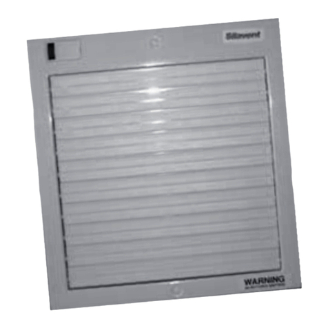
silavent SVC6 User manual

Installation Instructions
SVC6
Window/WallFans
ISSUE 1
08/11 LAB739R
230vAC-50Hz15W
HighSpeed/SingleSpeed 35W
LowSpeed 25W
IPX4Rating– Thisproductisdoubleinsulated.
ManufacturedintheUKby
Polypipe
Polypipe
Sandall Stones Road, Kirk Sandall Industrial Estate, Kirk Sandall, Doncaster DN3 1QR
Tel: +44 (0) 8443 715523 Fax: +44 (0) 8443 715524
www.polypipe.com/ventilation
www.polypipe.com

SVC6RANGE
SVC150B Standard
With pull-cord switch
With Timer
With Humidistat, timer and pull-cord switch over-ride
With Humidistat
Twin speed with pull cord switch
Twin speed with Humidistat and pull cord boost
SVC150PB
SVC150TB
SVC150HTB
SVC150HB
SVC150PBTW
SVC150HBTW
SILAVENT
WIND W/WALLFANS
The SVC6 range are axial extractor fans suitable for use in domestic kitchens and light
commercial environments. They may be used in other applications where a high level of
ventilation is required.
The SVC6 is designed primarily as a window fan but it can also be installed on a wall or
a ceiling but should not be ducted over 2 metres. When fixing through the wall a wall
fitting kit SVC901W is required.
N TES
PERF RMANCE
SINGLE SPEED ODELS 240 m3/h (67l/s)
TWIN SPEED ODELS
LOW SPEED 175 m3/h (48l/s)
HIGH SPEED 240 m3/h (67l/s)
Hole size for window fitting - 184mm (71/4”)
inimum thickness of glass - 4mm aximum 35mm
Hole size for wall fitting 170mm (63/4”) ProfessionalInstallers– PleaseleavetheseinstructionsfortheHouseholder

AGUIDET VENTILATI N
WHERET SITEY URFAN
Incorrect siting of an extractor fan can
severely impair its efficiency. It is
therefore, important that the fan is
correctly sited using the following
principles.
• To ensure maximum air flow through
the whole room, mount in the window,
wall or ceiling furthermost from the air
inlet point at high level.
• Do not position a fan where
temperatures are likely to exceed 50ºC
(for example above a cooker hob or
eye level grill).
• When installing in a room with an open
fire or stove without a balanced flue,
ensure that there is sufficient
replacement air to prevent the fan
drawing air back down the flue.
• A 230volt fan installed in a bathroom
must not be within reach of a person
using the bath or shower.
• Always use an in-duct or Low Voltage
Fan (SELV) to ventilate a shower
cubicle.
• When installed in a window, the fan
should be as high as possible and
should not be fitted in an opening
window if it can be avoided.
NOT FOR USE IN SHOWER
CUBICLES OR ABOVE BATHS
FITTED WITH A SHOWER
MAXIMUMR M
TEMPERATURES40ºC
PERATI N
All models are fitted with high technology thermo actuated shutters which operate
automatically. Allow up to 1 minute for shutters to open and up to 4 minutes to close.
D N TF RCESHUTTERS
M DELSVC150HBTW
These models are equipped with humidity control on slow speed and pull-cord switch
over-ride to high speed. The slow speed is intended to turn on when a pre-set humidity
has been exceeded and off when that level has been reduced. The fan may be operated
via the pull-cord switch at any time. The slow speed cannot be operated independently
of the humidity control.
TIMERANDHUMIDITYSENSITIVITYADJUSTMENT
TIMERM DELSSVC150TB/SVC150HTB
Isolate from power supply. Remove front cover. The timer adjuster is positioned at the
top and is turned clockwise for more over-run time and anti-clockwise for less. (Range is
30 seconds to approx 25 minutes - factory default is set at minimum).
HUMIDISTATM DELSSVC150HTB/SVC150HB/SVC150HBTW
Isolate from power supply. Remove front cover. The sensitivity adjuster is positioned at
the top. Turn clockwise for more sensitivity, anti-clockwise for less. (Range
50%RH–100%RH)
The humidity control may be tested by breathing through the sensor grille located at the
top of the fan unit. Please note that there is a 15 second delay between the sensor
operating and the fan starting.
D N T test the sensor with steam from a kettle.
MAINTENANCE
aintenance free, but should be cleaned at least once a year.
CLEANING
Isolate from power supply. The outside of the fan may be cleaned with a damp cloth and
washing-up liquid. If the fan unit is heavily soiled it should be removed from its mounting.
The main fan chassis can be cleaned with a damp cloth. Do not immerse in water. The
remaining parts may be cleaned with water and washing-up liquid. Dry and re-install.
The discharge grille may be removed from the window by removing the top and screws.
Clean as above and replace. It is not necessary to remove the surface mounting housing
and discharge grille spigot from window/wall to clean them.

ASSEMBLYANDFITTING
FSVC6
(seeCAUTI NandWARNINGonpage9)
M DELS:SVC150BwithSPEEDC NTR LLERANC841A
DISASSEMBLY
Remove front cover retaining screw (5) and lift off front cover (1), see note below.
REASSEMBLY
Reassemble the fan unit in reverse order. When reassembling the fan unit it is important
not to over-tighten any screw or the clamp nuts.
N TE: Liftingthetopedgeofthefrontcoverwillmakeiteasiertoremove.
WARNING
Positioning of the fan unit must be so as to avoid back flow of gases from open flue gas
or other open fire appliances. To prevent combustion gases entering the air inlet, this air
inlet must not be positioned above or within 1.5 metres of a combustion flue vent.
CAUTI N
Fans incorporating electronic control systems may be damaged if used in conjunction
with fluorescent lamps.
IFIND UBT,PLEASEC NTACT
CUST MERSERVICES N
08443715523
SPEED
CONTROLLER
SLOW
SPEED
ADJUSTMENT
ISOLATOR SWTCH
1 2 3 4
N
L
L
N
SpeedControlTerminals FanTerminals
1-Fan Line N- Neutral
2- Live In L- Live
3- Fan Neutral

WIRINGINSTALLATI N
WARNING:IsolatefromPowerSupplybeforecommencingwork
WIRINGREQUIREMENTSF RD MESTICELECTRICFANS
It is recommended that fans be connected into the lighting circuit, with double pole
(3mm) isolation provided before the room light switch and suitably fused, in accordance
with IEE Regulations.
Window Fans should be connected to power supply using a flexible cord with conductors
of between 0.75mm2and 1.5mm2only.
Wall and ceiling mounted fans for fixed wiring should be connected to the power supply
via a cable with solid conductors of 1mm2to 1.5mm2only.
IFIND UBTC NSULTAQUALIFIEDELECTRICIAN
WIND WFITTING
Strip the fan unit to it’s three components as described on page 4. Cut 184mm (71/4”)
hole in glass. This job is best done by a glazier.
Fig 1. Remove the 4 brass clamp nuts from the fixing kit then insert the discharge
grille spigot through the hole from the outside. Locate the surface mounting
housing over the studs. ake sure that the weather seals are not displaced.
Fit clamp nuts. Do not over-tighten.
Fig 2. Insert power supply flex through entry at the top of the surface mounting
housing and through the access hole in the main fan chassis. Fit the main fan
chassis to the surface mounting housing. Refer to Page 7 for wiring.
Fig 3. Once wiring is complete, fit the front cover.
D N TF RCETHESHUTTERS PEN RCL SEDAS
THISWILLDAMAGETHESHUTTERMECHANISM
N TE: odels SVC150TB & SVC150HTB feature a useful short run facility. This
is operated via the built in pull-cord switch. When used the fan will operate
for the time set into it’s integral timer then turn itself off. The fan cannot
be turned off using the switch. The short run facility is not intended to be
used as the main operating switch.
WARNING:IS LATEELECTRICITYBEF RESTARTINGW RK WARNING:IS LATEELECTRICITYBEF RESTARTINGW RK
M DELSVC150B
M DELSVC150PB,SVC150HB,SVC150PBTW,SVC150HBTW
M DELSVC150TB,SVC150HTB

WALLFIXINGKITSVC901W
We recommend the use of this fixing kit as it contains all the necessary parts to surface
mount or flush fit the SVC6 fan unit.
SURFACEM UNTING
Cut a hole through wall in desired position to take the 150mm duct supplied in the fixing
kit. It is important that there is at least a 5º downward slope towards the outside to allow
for condensation drainage.
The duct should be cut so that it is flush with both sides of the wall less 60mm which is
the length of the mounting socket adaptor body.
Strip the fan to its four main components as described on page 4. The outside grille
should be fitted into the discharge duct and secured to the outside wall using the wall
plugs and screws supplied with the fixing kit. At this point check that the 6” ducting and
mounting socket adaptor are flush with the inside wall before completing installation.
Use the surface mounting housing as a template to mark the fixing screws and cable
entry positions on the inside wall. ake sure surface mounting housing is accurately
lined up with discharge duct and adaptor.
Fix the surface mounting housing to the wall using the wall plugs and screws supplied
with the fixing kit ensuring that the electrical cable is through the cable entry hole in the
surface mounting housing.
Fit the fan into the surface mounting housing and make electrical connections as described
on pages 8 and 9 and refit front cover.
FLUSHM UNTING
Cut hole through wall in desired position. On the outside allow clearance for the 150mm
duct and on the inside allow clearance for the flush mount socket, this is a little larger
than the duct. It is important that there is a downward slope towards the outside to allow
for condensation drainage.
When the hole through the wall is complete, a length of adhesive sealing strip should be
fixed around the flush mount socket spigot. Now insert the flush mount socket into one
end of the 150mm duct and fit the assembly into position temporarily and mark duct for
cutting to length. If surface mount socket requires trimming, ensure that a depth of at
least 55mm is retained. The duct assembly should be flush with both sides of the wall.
When length is correct, grout the assembly firmly into position.
Strip the fan to its four main components as described on page 4. Assemble the fan as
previously detailed for surface mounting but discard the surface mounting housing and
complete the installation as previously described.
Note: When flush mounting the fan unit the power supply cable must be chased into
the wall surface. Apply the self adhesive sealing strip around the fan chassis
spigot before fixing to socket using wall plugs and screws supplied with fixing
kit.
ake electrical connections as described on page 8. Refit front cover.
Diagram is for illustration
purposes only. The fan purchased
may vary in looks from the diagram.
Diagram is for illustration
purposes only. The fan purchased
may vary in looks from the diagram.
Table of contents
Other silavent Fan manuals
Popular Fan manuals by other brands

Klarstein
Klarstein FIGO 10029345 manual

OSTBERG
OSTBERG RS Installation and directions for use
Airflow
Airflow QT 100T Installation and operating instructions
IV Produkt
IV Produkt Flexomix EXP Operation and maintenance

Klimair
Klimair TEMPERO ECO CERAM REMOTE Mounting, operation and maintenance

Elta
Elta Ezifit In-Wall SEIE Installation and maintenance instructions
iGenix
iGenix DF0029BL user manual
Unold
Unold CHROME Instructions for use

Craftmade
Craftmade OS60 installation guide

American Aldes
American Aldes AIRLET 200 Installation operation & maintenance

Natural Light
Natural Light Gable Solar Fan installation instructions

Princess
Princess 352600 Instructions for use
