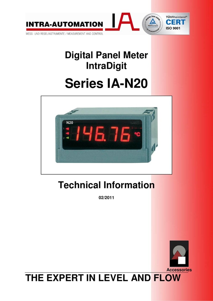
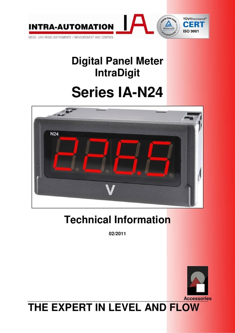
Intra Automation digiflow 515 Installation guide

Installation Instruction / Operating Manual
Softwareversion: 2.0 and up
DigiFlow 515
INTRA-AUTOMATION GmbH
Meß- und Regelinstrumente
Otto-Hahn-Straße 20
41515 Grevenbroich
Tel.: (49) 21 81/6 87 61
Fax: (49) 21 81/6 44 92
eMail: INTRA-Automation@T-Online.de
Dok.: df15
_
bae.doc\ Rev. 2.2 \ 26.11.97\had


Gas- and Steam Flowcomputer DigiFlow 515 Operating Manual
3
Directory
1 INTRODUCTION...............................................................................................................................................................................5
2 ORDERING DETAILS ......................................................................................................................................................................6
3 TECHNICAL DATA ..........................................................................................................................................................................6
4 ALGORITHMS...................................................................................................................................................................................8
5 OPERATION.......................................................................................................................................................................................9
5.1 FRONT VIEW ........................................................................................................................................................................................9
5.2 GENERAL.............................................................................................................................................................................................9
6 APPLICATION.................................................................................................................................................................................10
6.1 THE DIGIFLOW 515 AS GAS COMPENSATION CALCULATOR..................................................................................................................10
6.1.1 Parameter setting of the flow calculator:.................................................................................................................................12
6.1.2 Application for Ideals Gases ....................................................................................................................................................13
6.1.3 Application for General Gases.................................................................................................................................................14
6.1.4 Natural Gas..............................................................................................................................................................................15
6.2 THE DIGIFLOW 515 FOR THE STEAMING QUANTITY MEASURING..........................................................................................................16
6.3 THE DIGIFLOW 515 AS HEAT CONSUMPTION CALCULATOR..................................................................................................................17
6.3.1 Programming The Flow Computer...........................................................................................................................................18
6.4 FILTERING OF THE FLOW INPUT .........................................................................................................................................................19
6.5 CORRECTION OF THE NONLINEARITY .................................................................................................................................................20
6.5.1 Correction for the frequency input ...........................................................................................................................................20
6.5.2 Linearization for the analog input............................................................................................................................................20
7 PROGRAMMING AND PARAMETER SETTING......................................................................................................................21
7.1 KEY DESCRIPTION..............................................................................................................................................................................21
7.2 CONFIGURATION OF A SET..................................................................................................................................................................21
7.3 INPUT OF A NUMBER...........................................................................................................................................................................21
8 MENU TABLES................................................................................................................................................................................22
8.1 MAIN MENU......................................................................................................................................................................................22
8.2 BASE SETUP ......................................................................................................................................................................................22
8.3 MEDIUM PARAMETERS ......................................................................................................................................................................23
8.4 SIGNAL CHECK ..................................................................................................................................................................................23
8.5 FLOW PARAMETERS...........................................................................................................................................................................24
8.6 OPTIONS............................................................................................................................................................................................25
9 INPUT CIRCUITS............................................................................................................................................................................26
9.1 FREQUENCY SIGNAL...........................................................................................................................................................................26
9.2 ANALOG INPUTS.................................................................................................................................................................................28
9.2.1 Input of Pt100 RTD ..................................................................................................................................................................28
9.2.2 Analog 4-20mA input................................................................................................................................................................28
9.3 REMOTE SWITCHED FUNCTIONS..........................................................................................................................................................30
10 OUTPUT CIRCUITS......................................................................................................................................................................31
10.1 DIGITAL OUTPUT..............................................................................................................................................................................31
10.2 RELAY OUTPUT................................................................................................................................................................................32
10.3 RS232 OR RS485 INTERFACE..........................................................................................................................................................32
10.3.1 Hardware................................................................................................................................................................................32
10.3.2 Communication Protocol........................................................................................................................................................33
10.3.3 Printers Protocol....................................................................................................................................................................33
10.3.4 Host–Communication.............................................................................................................................................................33
10.3.5 Network communications........................................................................................................................................................34
11 OPTIONS.........................................................................................................................................................................................35
11.1 ANALOG OUTPUT .............................................................................................................................................................................35
11.2 CONTROL OF A SENSOR–PURGE–UNIT .............................................................................................................................................36
11.2.1 Time diagram Sensor–Purge–Unit.........................................................................................................................................36
11.2.2 Functional description: ..........................................................................................................................................................36
12 INSTALLATION............................................................................................................................................................................37
12.1 GENERAL.........................................................................................................................................................................................37
12.2 REAR VIEW .....................................................................................................................................................................................37
12.3 WIRING DESIGNATIONS....................................................................................................................................................................37
13 BLOCK DIAGRAM .......................................................................................................................................................................39
14 APPENDIX A ERROR DESCRIPTIONS......................................................................................................................................40
15 APPENDIX B PROPERTIES OF SOME GASES: ........................................................................................................................41
16 APPENDIX C APPLICATIONS (EXAMPLES)............................................................................................................................42

Gas- and Steam Flowcomputer DigiFlow 515 Operating Manual
4
Note.
The information in this document can be changed without previous announcement.
These instructions do not claim to cover all details or variations in equipment, nor to provide for every possible contin-
gency that may arise during installation, operation or maintenance.
Should further information be desired or should particular problems arise that are not covered sufficiently for the Pur-
chaser’s purposes, the matter should be referred to the local INTRA Sales Office.
The contents of this instructions manual shall not become become part of or modify any prior or existing agreement,
commitment or relationship. The Sales Contract contains the entire obligations of INTRA. The warranty contained in the
contract between the parties is the sole warranty of INTRA. Any statements contained herein do not create new warran-
ties or modify the existing warranty.
Directory of the symbols used in this handbook
Symbol Description SI unit US-unit
A Normalized Signal between 0 and 1 (0 ≡4 mA and 1 ≡20 mA – –
d specific Gravity. Ratio of the density of a gas to the density of air – –
f Frequency Hz Hz
hv, hrspecific Enthalpy at Flow Conditions kJ/kg kJ/kg
h0specific Enthalpy at Reference Conditions kJ/kg
kFk-factor (pulses/unit) for a frequency flowmeter. n/m3n/m3
NoTimebase Constant with which the flowrate is displayed:
1 for units/s,
60 for units/min.,
3600 for units/h,
86,400 for units/d.
– –
p Pressure at Flow Conditions. kPaabs psia
pbPressure at Reference Conditions. kPaabs psia
pkrit Critical Pressure of Gas. kPaabs psia
QEEnergy Value of Steam. MJ/TU BTU/TU
QMMass Flowrate. kg/TU lbs/TU
QVb Corrected Volume Flowrate. m3/TU ft3/TU
SMSpan of Mass kg/TU lbs/TU
SVSpan of Volume. m3/TU ft3/TU
SVb Span of Volume at Reference Conditions. m3/TU ft3/TU
T Temperature at Flow Conditions. K K
TbTemperature at Reference Conditions. K K
Tkrit Critical Temperature of Gas. K K
zfCompressibility at Flow Conditions – –
zbCompressibility at Reference Conditions – –
ρDensity at Flow Conditions. kg/m3kg/m3
ρbDensity at Reference Conditions. kg/m3kg/m3
υSpecific Weight of Steam at Flow Conditions. dm3/kg dm3/kg
υbSpecific Weight of Steam at Reference Conditions. dm3/kg dm3/kg
* TU = Time Unit (d, h, min, s)
Remark:
Are a temperature of 0°C and a pressure of 101,325 kPaabs as normalized conditions programmed, the vol-
ume unit will so be added with the prefix „N“ in the display, to point to this „NORM“-state. If a temperature of
15°C and a pressure of 101,325kPaabs are defined as normalized conditions, then the volume unit will be
prefixed by an „s“, to point to this „standard-conditions, which are often used at US-Units.

Gas- and Steam Flowcomputer DigiFlow 515 Operating Manual
5
1 Introduction
The DigiFlow 515 combines compensation for gas and vapors to the following equations:
1. Ideal Gas: Temperature and pressure correction, compressibility correction not required.
2. General Gas: Temperature and pressure correction with compressibility correction calculated using the
Redlich-Kwong1state equation. This equation is suitable for gases with known properties. Information
about common industrial gases are provided in the operating manual.
3. Natural Gas: Compressibility is calculated using the AGA-NX-19-mod equation for natural gases of low
gross caloric value.
4. Steam Flow Computer: Based on the IFC 1967.Mass flow correction of the flowing steam using pressure
and temperature.
5. Energy: The heat quantity is calculated based on enthalpy and mass flow.
6. Energy Balance: . Assuming a mass balance in upstream-and downstream pipe, an energy balance of the
loop is calculated.
Inputs from various of flowmeters are accepted. Examples of these sensors are (VORTEX),turbine, orifice
plate, averaging pitot tubes like (ITABAR-Flow sensor), wedges and target flowmeters.
To increase the measured flowrange of an ITABAR-Flow sensor, it is possible to use two differential pressure
transmitters whose ranges overlap with automatic crossover in the computer.
The device include a scaleable Pulse Output an two scaleable Alarm Relay Outputs.
Optionally this computer includes:
• Up to 3 Analog Outputs 0/4 – 20mA.
• RS485 – Interface.
• Control Relays for an Sensor–Purge–Unit.
A unique feature available with the serial interface is the ability to print flowrates and totals at programmable time
intervals. This enables the instrument to function as a data logger when used in conjunction with a printer, or
other storage device.
1Redlich & Kwong,, „An equation of State“, Chem Rev., vol. 44, p233, 1949

Gas- and Steam Flowcomputer DigiFlow 515 Operating Manual
6
2 Ordering details
Code Option or Feature
515 Gas- and Steam Flow Computer, Type: DigiFlow 515
Code Housing
S Panel mounting IP54 (Standard)
T Panel mounting with lockable transparent door IP55
Code Power Supply
2 230 V AC mains (Standard)
1 115 V AC mains
4 24 V AC/DC
Code Analog Output
X No Analog Output
1 One Analog Output
2 Two Analog Outputs
3 Three Analog Outputs
Code Communication Port
2 RS232 - Serial Interface (Standard)
4 RS485 - Multipoint Serial Interface
Code Sensor-Purge-Unit
S Without Relay Output
L With Relay Output for Sensor Purge Unit
3 Technical data
General:
Display: Backlighted, alphanumeric LC–Display, 2 rows, 16 cols. Each char is 0.276" high.
Keyboard: Sealed membrane keyboard with four keys.
Transmitter supply: 18 V / 100 mA; via keyboard adjustable, isolated.
Power: 115/230 V AC; 50/60 Hz internally switchable.
Optionally 24-28 V AC/DC
Power consumption 10 W @ 230 V AC without Options.
Operating Temperature:
32 – 131 °F
Housing: Enclosure: glass–fiber reinforced synthetic material; Front: aluminum keyboard membrane.
Face: Watertight to IP 54 (NEMA 4X equal)
Dimensions: 5.7" W ×2.8" H ×5.1" D
Panel cutout: 5.4" W ×2.6" H
Programming and Configuration:
Handheld: There is no handheld terminal required. All necessary constants and parameters are programmed
using the keypad.
Language: German, English or French selectable.
Frequency Input:
Frequency Range: 0.25 - 10 kHz Input 1.
0.25 - 500 Hz Input 2.
Input Circuits: Most AC, logic and proximity switches accepted. 0.5 – 50 Vpp.
Non–Linear Correction:
Up to 12 points for curve fit.

Gas- and Steam Flowcomputer DigiFlow 515 Operating Manual
7
Analog Input 4 – 20 mA:
Inputs: 2 for flow (split range), 1 for pressure, and 1 for temperature, for flow correction, or
2 for flow (split range) and 2 for pressure for energy–balance.
Input Impedance: 120 Ω.
Circuit: All inputs are isolated, no common ground.
RTD Input:
Range: -310 to +1472°F.
RTD Type: Pt100 according to DIN 43760.
Non–Linear Correction: The non–linearity of the RTD is internally compensated.
Pressure Input:
Type: Absolute or gauge.
Span: The pressure at 4mA and 20mA are programmable. Linear interpolation for all other points.
Atmospheric pressure: If a gauge pressure sensor is used, the atmospheric pressure must be entered.
Pulse Output:
Pulse Width: Adjustable between 10 ms and 90 ms.
Duty Cycle: ≥1 : 1.
Logic: Open Collector, Active Low.
Current sinking: max. 100 mA.
Pulse generation: The pulse count is proportional to the counter difference in selectable units of 10 (1, 10, 100,
....100000).
External Keyboard:
Function: One input controls the display and one input resets the total-counters.
Circuit: An input voltage higher than +18 V is detected.
Communication Port:
Type: An RS232 interface is provided. Optionally there is a RS485 multipoint communication interface
for up to 32 instruments connected to a common bus.
Baud Rate: 300 – 9600 Baud.
Data Bits: 7 or 8 selectable.
Parity: None, even or odd.
Stop Bits: 1 or 2 selectable.
Data logging: Output in intervals up to 9999 min or by key stroke.
Relay Output:
Function: High– and Low–flow rate alarms based on the flow rate, mass, corrected volume, or energy.
Form: Normally open. (SPST)
Max. Voltage 250 V AC
Max. Current 6 A AC

Gas- and Steam Flowcomputer DigiFlow 515 Operating Manual
8
Options:
Analog Outputs:
Function: Selectable: Output current proportional to standard display or of other Parameter See Table on Page
35. Setpoints at 4 mA and 20 mA, linear interpolation between.
Output Span: 0 – 20 mA or 4 –20 mA selectable.
Resolution: 12 Bit
Max. Load: 500 Ωinternally powered.
800 Ωexternally 24 V powered.
Powering: If there is no external supply >15V the output will be internal powered automatically.
Control of a Sensor–Purge–
Unit:
Function: Two relays control the solenoid activated valves of a Sensor Purge Unit. During the purging time
and an additional selectable time after purging, the flow input is maintened.
Time between purging: 10 minutes to 31 days 23 hours 50 minutes.
Purge Duration: 1 to 999 s
Time Constant: 1 to 99 s
4 Algorithms
Ideal Gas:
Display: Corrected Volume (m3or SCF), Mass (kg or lbs)
Temperature Range: -273 °C (-460 °F) to +1,000 °C (1,832 °F)
Pressure Range: 0 kPaabs (0 psia) to 100,000 kPaabs (14,514 psia)
General Gas:
Gases: Handles most gases where critical temperature, critical pressure and specific gravity are known.
Compressibility: Calculation using the Redlich–Kwong equation.
Ranges: Same as Ideal Gas.
Natural Gas:
Gases: Natural Gases with a gross caloric value of 31.8 MJ/m3to 38.8 MJ/m3, specific gravity of 0.554 to
0.75, density at reference conditions of 0.716 kg/m3to 0.970 kg/m3, and a CO2– and N2– molar
fraction of 15% each.
Compressibility: Uses the AGA–NX–19–mod equation.
Temperature Range: -40 °C (-40 °F) to 115,6 °C (240 °F).
Pressure Range: 101.325 kPaabs (14.7 psia) to 13,790 kPaabs (2,001 psia).
Steam:
Calculation: Uses 1967 IFC Formulation (ASME) equations to calculate specific weight and enthalpy of steam.
Steam Type: Liquid Water, saturated and superheated steam.
Temperature Range: 0.01 °C (32.02 °F) to 800 °C (1,472 °F).
Pressure Range: 0 kPaabs (0 psia) to 100,000 kPaabs (14,514 psia).
Saturated steam: Either the temperature or pressure input required (not both).

Gas- and Steam Flowcomputer DigiFlow 515 Operating Manual
9
5 Operation
5.1 Front view
5.2 General
The DigiFlow 515 work with a CMOS microprocessor that processes all measurements and takes all control-
ling functions.
All operation parameters and rake constant are programmable and get in a nonvolatile memory filed which
keeps the information after energy loss for at least 40 years.
About the alphanumeric display can information about the parameters and measuring units necessarily be
called.
During the parameter setting can be selected, whether the flow rate is reported as volume or mass when at
gas calculator or as mass or energy when at steaming calculator.
The following data can be fetched in the display by means of the SCAN key during the ongoing measuring: (
also see ` key description ' page 21 )
Gas flow: • Corrected volume (m3or SCF)
• Mass (kg or lbs)
• Temperature and pressure (°C or °F resp. kPa or psi)
• Compressibility factors [except ideal gas]
• Date and time
Steaming flow: • Mass (kg or lbs)
• Energy (MJ or BTU)
• Temperature and pressure in upstream path (°C or °F resp.
kPa or psi)
• Specific Weight and Enthalpy in upstream path (dm3/kg or
kJ/kg)
• Temperature and pressure in downstream path (°C or °F
resp. kPa or psi) [only when energy balance]
• Specific Weight and Enthalpy in downstream path (dm3/kg
or kJ/kg) [only when energy balance]
• Date and time
By means of the TOTAL-key the display changed of the present flow rate and the accumulated flow. If on a
higher level display is switched back to main level.
A higher display level is also exited without any key actuation after about 60 seconds.
If the accumulated flow is displayed, the sum counters can be deleted about the CURSOR-key. This function
can be inhibited at the configuration.
By simultaneous pressure the TOTAL-key and the SCAN key the calculator is switched into the parametrising
and configuration mode. Herein all necessary inputs are made for the special application. The keys partly get
another function for this menu level. By means of the SCAN-key is scrolled through the sub-menus of a menu
level. The ENTER-key then serves the subroutine-call to the selected menu item. At the input of numerical
values about the CURSOR-key an input place is selected which is represented by the flashing cursor. This
place then can be adjusted to the desired value by means of the SCAN-key. this can be set to the value ‘0’ by
pressing the TOTAL–key.
LED-Indikators
of TOTAL-Key,
and Alarm
relays
Alphanumeric LC-
Display 2 Rows /
16 Columns
TOTAL CURSOR SCAN ENTER

Gas- and Steam Flowcomputer DigiFlow 515 Operating Manual
10
6 Application
6.1 The DigiFlow 515 as gas compensation calculator.
Flow equations for gases
This chapter is only of meaning for flow measurings at gases. If the flow medium is steam, you can change
for chapter 5.2 on page 16 at once.
The flow calculator DigiFlow 515 process the input signals of a wide range of flowmeters by the equations
defined below.
Mass flow and corrected volume are shown and processed in SI units. For explanation about the following
abbreviations see listing at the beginning of the operating instruction.
2 formulas form the basis for all other equations:
!Specific Gravity
d=Molecular Weight of Gas
Molecular Weight of Air
d=Molecular Weight of Gas
28.9625 [1]
"Density of a gas ρ0, at Reference Conditions:
in SI-Units:ρ03
34834
=⋅⋅
⋅
.dp
zT kgm
b
bb
[2]
The conditions all calculations are being based (‘NORM“-conditions), will be entered by the user. Most times
these will be set to:
•Temperature 0 °C (273.15 K) and Pressure 101.325 kPaabs
A: Volumetric Flowmeters With Frequency Output.
(e.g. VORTEX, turbine or PDF with Pulse Output).
QNf
kp
p
T
T
z
z
Vb
Fb
bb
f
=⋅⋅⋅⋅
0[4]
QQ
MVb
=⋅
ρ
[5]

Gas- and Steam Flowcomputer DigiFlow 515 Operating Manual
11
B: Volumetric Flowmeters with 4–20mA Output.
(e.g. VORTEX, turbine or PDF with Analog output)
QS
p
pT
Tz
zA
Vb V
b
bb
=⋅⋅⋅⋅
[6]
QQ
MVb
=⋅
ρ
0[5]
C: Differential Pressure Flowmeters With 4–20mA Output And a Square Law Relationship.
(e.g. Orifice Plates, ITABAR-Probes, Pitot Tubes, etc.)
QS p
pT
Tz
zA
Vb Vb
b
bb
=⋅ ⋅ ⋅ ⋅ [7]
QQ
MbVb
=⋅
ρ
[5]
D: Differential Pressure Flowmeters With 4–20mA Output And a Linear Flow Relationship.
(e.g. D.P. transmitter with integrated square root extractor.)
QS p
pT
Tz
zA
Vb Vb
b
bb
=⋅ ⋅ ⋅ ⋅
[8]
QQ
MbVb
=⋅
ρ
[5]
Pressure and temperature signal are still square rooted, the flow signal are not. This is because the output
from the D.P. transmitter isn’t truly volumetric, but will be affected by a change in density of the gas being
measured.
E: Dual Differential Pressure Flowmeters With 4–20mA Output.
To increase the range over which flow can measured, two D.P. transmitters with different spans can be con-
nected across a common D.P. device (e.g. Orifice Plate or ITABAR-Probe). Depending on the Output of the
transmitter, equations 5 and 6 or 7 and 8 are used. Separate scaling must be programmed for each transmit-
ter.
Transmitter #2 is selected when signal from Transmitter #1 is higher than 19mA.

Gas- and Steam Flowcomputer DigiFlow 515 Operating Manual
12
Example No. 1:
With an orifice plate the flow shall be measured in the range of 0-2,000 m3/h, what to a Measuring range rela-
tionship of 10:1 corresponds. The two transmitters are spanned as follows:
Transmitter 1: 0 600m3/h
Transmitter 2: 0 2,000m3/h
In range up to 600m3/h Transmitter 1 is used, at flow rates above 600m3/h transmitter 2 is used. Since D.P.
transmitters are accurate over a 3:1 range, then the system will provide reliable readings between 200 and
2000 m3/h, which is a 10:1 range.
6.1.1 Parameter setting of the flow calculator:
For the correct function of the flow calculator the following parameters must be entered:
• kFk–factor of flow measuring instruments with frequency output
• SVb /SVSpan (for analog flowmeters)
• TbReference temperature
• pbReference pressure
• d Specific gravity of the gas
The flow calculator gets the signals for flow, pressure and temperature. In dependence of the chosen gas
equation the compressibility factor is taken into account and the density calculates.
Which parameters are to be entered, can be looked up in chapters 5.4.
6.1.1.1 Programming the Span as Mass
It is possible to enter the measuring range of the flow measuring instrument as mass flow. The computer will
then calculate the span as:
SS
Vb
M
b
=
ρ
[9]

Gas- and Steam Flowcomputer DigiFlow 515 Operating Manual
13
Example No. 2:
A flowmeter produced a mass flow of 1,000kg/h. Temperature of 30°C, pressure of 220kPa and specific
Gravity of 1.52.
Using equation [2]gets:
ρ= ⋅⋅
⋅+
34834 152 220
1 30 27315
..
(.)
ρ=384 3
.kgm(assuming: zb= 1)
Therefore from equation [9]the span will be: SVb = 260 m3/h.
If the span is programmed as mass SM= 1,000kg/h at reference conditions of 30°C and 220kPa, then the
display of mass flow and volume flow referenced to these conditions.
Example No. 3:
Shall the volume flow from above example calculated into „standard“ conditions, then the setable values are
15°C and 101.325kPaabs.
Then the span will be: SVb = 537.2 sm3/h.
6.1.2 Application for Ideals Gases
If the influence of the compressibility on gases can be ignored, then the factors Zb and Zf in the equations 1
to 8 will be set to "1".
The computings become substantially simpler with these approximations. These approximations are applica-
ble for:
• Gases of 1. Gas range (also at higher pressures)
• Gases of 2. Gas range up to 20bar
Example No. 4:
A VORTEX is used to measure oxygen in a pipe at 25°C and 200kPaabs. The VORTEX produces 9,500
Pulses/m3and the flowrange is 100 to 1,000m3/h.
Determine the flow parameters which need to be programed into the instrument for it to display the flowrate
and total flow as both mass and corrected volume to standard conditions.
From the table, the molecular weight of oxygen is: 31.9988mol/g
From equation (1):
dgmol
gmol
==
319988
289625 1105
.
..
According to ISO 5024, Standard Conditions are 15°C at 101.325kPa. Hence the following values are pro-
grammed into the instument:

Gas- and Steam Flowcomputer DigiFlow 515 Operating Manual
14
Scaling Factor (k-
Factor): 9,500 Pulses/m3
Specific Gravity d: 1.105
Base Temperature: 15°C
Base Pressure: 101.325 kPa
Time Base: hours
Other parameters can be programmed as required.
The instrument will now display the corrected volume and mass flowrates of the gas.
Example No. 5:
The same vortex meter installation, as detailed in Example 4, has a 4–20mA output. The instrument produce
at 0m3/h a current of 4mA and at 1,000m3/h a current of 20mA.
Determine the parameters necessary for the Configuration.
If the calculator gets a linear 4–20mA signal, then the following parameters are to program:
Span: 1,000 m3/h
Specific Gravity: 1.105
Base Temperature: 15 °C
Base Pressure: 101.325 kPa
Time Base: hours
6.1.3 Application for General Gases
For general Gases the compressibility is calculated using the Redlich-Kwong-equation. Therefor it is neces-
sary to know the critical temperature and the criticial pressure of the gas. From these parameters, the com-
pressibility factors zband zfare calculated for a gas..
Datas of common gases are listen in Appendix B Properties of Some Gases:
Equations 1 to 9 are used to calculate the corrected volume and mass.
Example No. 6:
A flow of Hydrogen via an orfice plate shall be calculated under consideration of the compressibility. Which
constants are required?
Tk: -239.9°C
pk: 1,296.9kPa
d: 0.0696

Gas- and Steam Flowcomputer DigiFlow 515 Operating Manual
15
6.1.4 Natural Gas
For natural gas of low caloric value the compressibility factor is calculated using the AGA-NX-19-mod equa-
tion. These factors are used with equations 4 to 8.
To calculate this compressibility factor following paramerters are to be entered in consideration of their limita-
tions.
Specific Gravity d 0.554 to 0.75
mol% CO20 - 15%
mol% N20 - 15%
Temperature and pressure must be within following ranges:
Temperature: -40 bis 115°C
Pressure: 0 bis 137.9 barabs

Gas- and Steam Flowcomputer DigiFlow 515 Operating Manual
16
6.2 The DigiFlow 515 for the steaming quantity measuring
The DigiFlow 515 incorporates equations to calculate flows of water , satirized steam and superheated
steam over the following range:
Pressure: 0kPaabs bis 100,000kPaabs (0 psia to 14,513.8 psia)
Temperature: 0.01°C bis 800°C (32.02°F bis 1,472°F)
When measuring saturized steam, ist is possible to renounce of either the pressure input, or the temperature
input, since, on the saturation curve, there is a corresponding pressure for every temperature and vice versa.
For superheated steam and water, it is necessary to use both inputs.
Both the mass flow and enthalpy (heat content) are calcuated internally based on the 1967 IFC (ASME) For-
mulations. The equations use the pressure and temperature input values to calculate:
the specific Volume of steam: νin dm3/kg and
the specific Enthalpy: h in kJ/kg
A: Volumetric Flowmeter with Frequency Output
(e.g. VORTEX, Turbine etc.)
Mass Flow / SI–Units: QNf
k
MSI
F
()
=⋅
⋅⋅
1000 1
0
υ
[11]
Mass Flow / US–Units: Qf
k
MUS
F
() .
=⋅⋅
62 425 1
υ[12]
Note: when using US–Units k–factor must be entered in Pulses/ft3.
Energy / SI–Units: QQh
ESI MSI
() ()
=⋅
1000 [13]
Energy / US–Units: QQh
EUS
MUS
()
()
.
=⋅
⋅
045359 1000 [14]

Gas- and Steam Flowcomputer DigiFlow 515 Operating Manual
17
B: Volumetric Flowmeter With 4-20mA Output
(e.g. VORTEX, Turbine with Analog Output etc.)
Mass Flow / SI–Units: QSA
MSI V
()
=⋅⋅
1000
υ
[15]
Mass Flow / US–Units: QSA
MUS V
() ,
=⋅⋅
62 447
υ
[16]
Energy: Use equations 13 and 14
C: Differential Pressure Flowmeter with 4-20mA Output And A Square Law Relationship.
(e.g. Orifice Plates, ITABAR–Probe, Pitot Tubes, etc.)
Mass: QS A
MM
b
=⋅ ⋅
υυ
[17]
Energy: Use equations 13 and 14
D: Differential Pressure Flowmeter with linear 4-20mA Output
(e.g. Transmitter With Internal Square Root circuit)
Mass: QS A
MM
b
=⋅ ⋅
υυ
[18]
Energy: Use equations 13 and 14
E: Differenzdruckmessung mit 2 Eingangssignalen
To increase the range over which flow can measured, two D.P. transmitters with different spans can be con-
nected across a common D.P. device (e.g. Orifice Plate or ITABAR-Probe). Depending on the Output of the
transmitter, equations 5 and 6 or 7 and 8 are used. Separate scaling must be programmed for each transmit-
ter.
Transmitter #2 is selected when signal from Transmitter #1 is higher than 19mA.
6.3 The DigiFlow 515 as heat consumption calculator
If the DigiFlow 515 is uded as heat consumption calculator, it will be presumed a mass continuity in a closed
loop, that means the quantity of the pouring out medium is the same as streaming in. Therefore ,in this case,
the factor ‘h’ (enthalpy) will be replaced by the factor ‘∆h’, the diffence of both enthalpies. Both pressure and
temperature in this case are investigated in the downstream loop. Therefor it is completely same which state
the medium takes in the downstream loop. If the calculator is used in this mode, the temperature exclusively
by means of the Pt100–direct inputs be investigated, since the analog temperature input in this case becomes
the pressure input of the downstrem loop.
.

Gas- and Steam Flowcomputer DigiFlow 515 Operating Manual
18
6.3.1 Programming The Flow Computer
So that the flow calculating machine can determine the exact flow according to equations 11 to 18, a number
of parameters have to be entered:
kFk-Factor (Flow Meters with Frequency Output)
SMSpan (for Analog Outputs)
υ
υυ
υbBase specific weight at which the span is deter-
mined.
The calculator will be measure the flow input A (normalized between 0 and 1), the temperature and the pres-
sure to calculate the specific weight, and enthalpy.
Example No. 7:
A VORTEX (k-Factor 68.32 Pulses/ft3) is used at saturized steam. The flow output shall be in lbs/hour.
What are the parameters to be programmed?
The calculator should be programmed for steam measurement at a frequency meter. Cause steam is satu-
rated, it is only necessary to use either the pressure input or the temperature input. Becaus of cost the tem-
perature sensor is used. Then the following parameters are to be entered.
Units: US
k-Factor: 68.32
Time Base: hours
Example No. 8:
A differential pressure transmitter across an orifice plate outputs 20mA at a flow of 10,000kg/h. Design pres-
sure is 1,300kPaabs and a specific weight of 216.5dm3/kg. The flowrate is required in kg/h and the caloric
value in MJ/h. What are the parameters to be programmed?
From the steam table we read a temperature of 350°C at 1,300kPaabs and a specific weight of 216.5dm3/kg.
Steam is in superheated state. Following parameters are to be entered for steam flow measuring with analog
input and square root relationship.
Units: SI
Span: 10,000
Base Temperature: 350°C
Base Pressure: 1300kPa
Time Base: hours
Type of Steam: superheated

Gas- and Steam Flowcomputer DigiFlow 515 Operating Manual
19
6.4 Filtering of The Flow Input
Reading the instantaneous measurand correctly often is impossible because of the frequency fluctuations or
output current fluctuations of the flow measuring instrument created by the pulsating flow.
Therefore the flow calculator is provided with a digital filter which average out these fluctuations of the flow
signal and facilitates through this a more precisely reading of the measured values.
The following diagram shows an input signal pulsating and the effect of the filter on this signal.
unfiltered
Flow
filtered
Time
As guideline to the degree of filteringto be used, the following table shows the response to a step change in
input.
The value AF is the entered filter constand.
The times, after the value reported on the display 90 or 99% of the at the ending worth reaches, is indicated
in seconds. For the value AF = 1 therefor no filtering is executed.
AF 90% 99%
1 0 0
2 1 2
4 2 4
6 3 6
10 5 11
15 8 17
20 11 22
25 14 28
35 20 40
45 25 51
60 34 69
75 43 86
90 52 103
99 57 113
Table 1: Response time in seconds on a volatile modification of the input signal

Gas- and Steam Flowcomputer DigiFlow 515 Operating Manual
20
6.5 Correction of The Nonlinearity
6.5.1 Correction for the frequency input
Known nonlinearities of a flow measuring instrument can be corrected.
12 frequencies and scale factors are available to this. Data on the flowmeter non-linearity can usually be sup-
plied by the flowmeter manufacturer in the form of a Calibration Certificate, and is the result of individual tests
on flowmeter over a range of flowrates. The certifikate will list a number of flowrates or frequencies with the
measured k-factor at each flowrate.
The following diagram shows an example for the different scaling factors at various frequencies of an arbi-
trary flow measuring instrument. The broad black turn stands for the current scaling factor of the set, and the
narrow line is for the approximation in the flow calculator.
Scaling Factor
Frequency
Factor 4
Factor 3
Factor 2
Factor 1
Factor 5
Factor 6
F6 F5 F4 F3 F2 F1 F max
The curve between the single dots was won by linear interpolation, except for factor 1 which maintains a con-
stant value between Frequency 1 and the maximum input frequency.
During Calibration, the user have to enter a frequency and the corresponding k-factor for each of maximimum
12 points.
If a frequency with 0Hz is entered, the program doesn't expect any further correction data. If all 12 correction
points are used, the 12th frequency is set on 0Hz automatically.
6.5.2 Linearization for the analog input
Is only a flow signal to the flow calculator connected, a linearization can be programmed for this to compen-
sate for deviations of flow signal and actual flow. Up to 12 Dots can be entered, between worth be interpo-
lated linearly. The correction is done at the standardized device signal ( 0 1 ) , so that measure begin and
measure end are not affected. Programming of corrections points start with ‘1’, if a ‘0’ is entered no further
inputs are accepted.
The flow correction is defined as:
QSpanA
C
=⋅
Note:
The sqare root relationship for conventional differential pressure flow devices is handled separately and not by the liear-
ity correction described in this section.
Table of contents
Other Intra Automation Measuring Instrument manuals
Popular Measuring Instrument manuals by other brands

philippi
philippi PSM 2 instruction manual

TFA
TFA 31.1141 instruction manual

Niigata seiki
Niigata seiki GVC KDE Series user manual

ADA INSTRUMENTS
ADA INSTRUMENTS ProDigit MICRO operating manual

SBC
SBC Saia PCD ALE3D5FS10 Series Assembly and operating instructions

Honeywell
Honeywell SmartLine RMA801 user guide