Intra Automation IntraDigit IA-N24 Series Manual

THE EXPERT IN LEVEL AND FLOW
Accessories
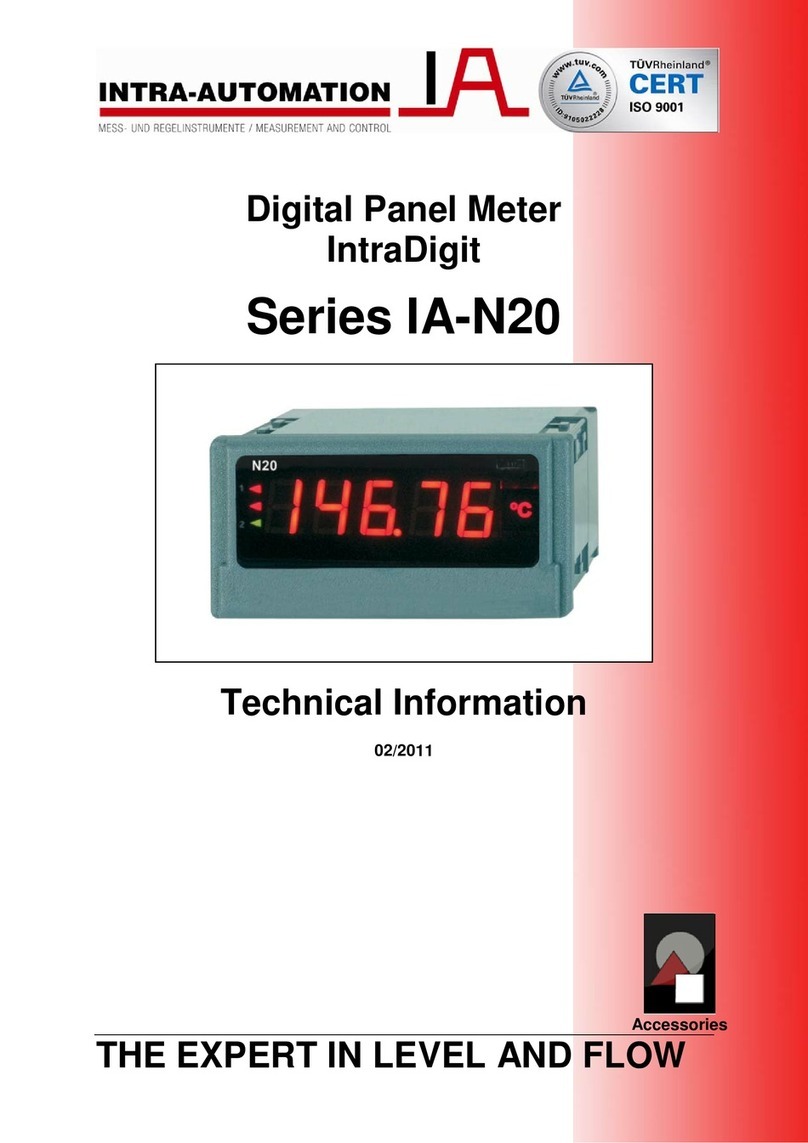
Digital Panel Meter
IntraDigit
Series IA-N24
Technical Information
02/2011

IA-N24 Technical Information Intra-Automation
- 1 -
Intra-Automation
Technical Information
02/2011
Technical details subject to be changed without notice.
For comments regarding this brochure, please contact:
info@intra-automation.de

Intra-Automation Technical Information IA-N24
- 2 -
IA-N24
IntraDigit
Digital Panel Meter
List of Contents:
Chapt. Title Page
1 Features 3
2 Application Example 3
3 Technical details 4
4 Electrical Connection 4
5 Ordering code 5

IA-N24 Technical Information Intra-Automation
- 3 -
1 Features
Designed for measurement of DC voltage or DC current, temperature through Pt100
thermometers, J, K thermocouple, AC voltage and AC current.
4-digit LED display (20 mm digit height)
Programmable parameters through the PD14 programmer
- Precision of displayed results (decimal point)
- measurement averaging time
- recounting of indications (individual characteristic)
- automatic or manual compensation: temperature of cold ends (for J, K) or wire resistance
(for Pt100)
2 Application example
Measurement and display; temperature, analog signals, DC current & voltage, AC current & voltage
I
A
-N24
PD 14
programmer
PC computer/
configuration
through
LPConfig
program
current
Pt100
temperature
sensor
60 mW
Supplying output
24 V DC

Intra-Automation Technical Information IA-N24
- 4 -
3 Technical details
Inputs
Type Measuring ranges Parameters Overloads Errors
-11 mV…-10 mV…60 mV…66 mV
66 mV…-60 mV…60 mV…66 mV
-0,5V…0 V…10 V…11 V
-11 V…-10 V…10 V…11 V
Input resistance: 1 M
-1 mA…0 mA…20 mA…22 mA Input resistance: 10 1%
IA-N24S
3,6 mA…4 mA…20 mA…22 mA Input resistance: 10 1%
Short term overload (1s):
- voltage input: 10 Un
- current input: 5 In
Sustained overload:
110 % Un, 110 % In
Basic error:
(0,2% of range + 1 digit)
Additional error from ambient
temperature changes:
(50 % of basic error)
Pt100 -50…150 °C
-50…400 °C
Current flowing though the
sensor: 300 µA
Resistance of wires conn.
RTD with the meter:
- max. 5 (per wire) for
automatic compensation
- max. 10 (per wire) for
manual compensation
Thermocouple
Type J -50…1200 °C
IA-N24T
Thermocouple
Type K -50…1370 °C
Short term overload (1s):
Input of sensors: 30 V
Basic error:
(0,2% of range + 1 digit)
Additional errors:
- compensation of cold junction
temperature changes:
0,2 % of range
from ambient temperature
changes:
(50 % of basic error)
1…100…120 V AC
2,5…250…300 V AC
4…400…600 V AC
20…500 V AC
(in voltage range: 24…480 V)
Input resistance: 2 M
0,01…1…1,2 A AC Input resistance: 10m10%
IA-N24Z
0,05…5…6 A AC Input resistance: 2m10%
Short term overload (1s):
Voltage input: 2 Un (1000 V),
Current input: 10 In
Sustained overload
150 % Un (for 400 V input)
120 % (for remaining inputs)
120 % ln
Basic error:
- voltage and current:
(0,5% of range + 1 digit)
- frequency:
(0,02% of range + 1 digit)
Additional error from ambient
temperature changes:
(50 % of basic error)
IA-N24H 0…100…120 V DC
0…250…275 V DC
-120…-100…100…120 VDC
-300…-250…250…300 VDC
-600…-400…400…600 VDC
Input resistance: 2 M
-1,2…-1…1…1,2 A DC Input resistance: 10m10%
-6…-5…5…6 A DC Input resistance: 2m10%
Short term overload (1s):
Voltage input: 2 Un (1000 V),
Current input: 10 In
Sustained overload
150 % Un (for 400 V input)
120 % (for remaining inputs)
120 % ln
Basic error:
(0,2% of range + 1 digit)
Additional error from ambient
temperature changes:
(50 % of basic error)
Outputs
For N24S and N24T Output for supply of external transducers 24 V 5 %, 30 mA
External features
Weight 0,25 kg
Overall dimensions 96 x 48 x 64 mm (with terminals)
Protection grade IP65 (Front side) IP10 (Terminal side)
Display 4-digit LED display, 20 mm height, red Indication range: -1999…9999
Rated operating conditions
Supply voltage 230 V 10 % AC (45…65 Hz); 110 V 10 % AC (45…65 Hz);
24 V 10 % AC (45…65 Hz);
85..253 V AC (40…400 Hz)or DC; 20..40 V AC (40…400 Hz)or DC; Power consumption 6VA
Temperature Ambient: -10…23…55 °C Storage: -25…85 °C
Relative Humidity 95 % Condensation inadmissible
Operating position Any
Preheating time 30 min
Averaging time 0.5 s 1 second default set
Safety and compatibility conditions
Electromagnetic compatibility Noise immunity acc. to EN 61000-6-2
Noise emissions acc. to EN 61000-6-4
Isolation between circuits Basic
Pollution grade 2
Installation category III (for the 400 V option – category II)
Maximal phase-to-earth operating
voltage For supply circuits: 300 V, for measuring circuits:
600 V, cat. II
For other circuits: 50 V
Altitude above sea level 2000 m
acc. to EN 61010-1

IA-N24 Technical Information Intra-Automation
- 5 -
4 Connecting diagrams
Electrical connection of the N24S meter
Electrical connection of the N24T meter
Electrical connection of the N24Z and N24H meters for voltage measurement (frequency: only N24Z)
Electrical connection of the N24Z and N24H meters for current measurement
Connections of N24T measuring inputs
Resistance thermometer in a
two-wire system with manual
compensation
Resistance thermometer in a
three-wire-system with
automatic compensation Thermocouple of J or K type

Intra-Automation Technical Information IA-N24
- 6 -
5 Order codes
Code Description
IA-N24 Digital panel meter
Kind of input:
S standard: voltage, current
T temperature: thermocouples, resistance thermometers
Z AC signals
H DC signals: high voltage and high current
Input
X see table 1
Power supply:
1 230 V AC
2 110 V AC
3 24 V AC
4 85…253 V AC/DC with supply output 24 V/30 mA*
5 20…40 V AC/DC with supply output 24 V/30 mA*
Unit
XX see table 2
Version
00 standard
NS non-standard settings (please see example)
XX custom-made**
Language
E English
X other**
Certification
0 without additional quality inspection certificate
1 with additional quality inspection certificate
X On request**
IA-N24
*only for N24S and N24T
**Please contact manufacturer
Table 1: Input signals
Code N24S N24T N24Z N24H
1 0…20 mA Pt100: -50…150
°C 100 V AC 100 V DC
2 4…20 mA Pt100: -50…400
°C 250 V AC 250 V DC
3 0…60 mV Thermocouple J 400 V AC 400 V DC
4 0…10 mV Thermocouple K 1 A AC 1 A DC
5 60 V 5 A AC 5 A DC
6 10 V 20…500 Hz 0…100 V DC
7 0…250 V DC
Table 2: Unit codes
Code Unit Code Unit Code Unit
00 without 06 mA 12 bar
01 °C 07 kA 13 kPa
02 % 08 kV 14 MPa
03 A 09 Hz XX On order**
04 V 10 turns
05 mV 11 rpm
**Please contact the manufacturer

IA-N24 Technical Information Intra-Automation
- 7 -
Order examples:
Example 1: N24Z-2-1-04-00-E-0 means:
N24Z meter for AC signals, input: 250 V AC, Power supply: 230 V AC, unit: V, 00- standard version,
English language without extra certification requirements
Example 2: N24S-1-4-02-NS-E-1 + description:
Parameter Range/Value
Decimal point 000,0 for I, U
Averaging time 1 s
Upper overflow of measurement 9999
Lower overflow of measurement -1999
Individual characteristic enabled
Parameter aof the individual characteristic 5
Parameter bof the individual characteristic 0
- means: N24S meter for DC signals, input: 4…20 mA supply: 85…253 V AC, with supply output: 24
V/ 30 A, unit %, non standard settings, display range 0…100.0, English language, with extra certificate
When ordering a meter with parameters different from the standard, all parameters have to
be provided!

Intra-Automation Technical Information IA-N24
- 8 -
Besides the products covered by this brochure, Intra-Automation GmbH also manufactures other high-
quality and high precision instruments for industrial measurement tasks. For more information, please
contact us (contact details on the backside of this brochure).
Flow measurement
Itabar®-Flow Sensor IntraSonic IS210 Ultrasonic Flow Meter
Level measurement
ITA-mag. Level Gauge MAGLINK Level Indicator
Other Measurement Tasks:
DigiFlow Flow and Level Computers IntraCon Digital Controllers IntraDigit Digital Indicators / Meters

IA-N24 Technical Information Intra-Automation
- 9 -
International Headquarters: Sales Office for the BENELUX:
Intra-Automation GmbH B.V. Intra-Automation HTP
Otto-Hahn-Str. 20 PO Box 10
41515 Grevenbroich 4730 AA Oudenbosch
GERMANY THE NETHERLANDS
+49 – (0) 21 81 / 7 56 65-0 +31 – (0)165 – 32 22 01
+49 – (0) 21 81 / 6 44 92 +31 – (0)165 – 32 29 70
info@intra-automation.de info@intra-automation.nl
www.intra-automation.com
This manual suits for next models
5
Table of contents
Other Intra Automation Measuring Instrument manuals