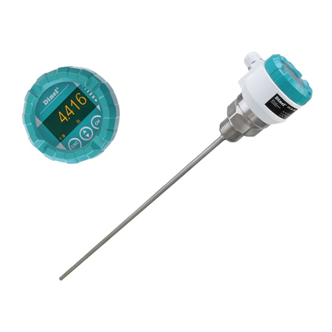
Dinel CLM-36-10 User manual

Read the instructions published in this manual carefully before the rst use of the sensor.
Keep the manual in a safe place. The manufacturer reserves the right to make changes without prior notice.
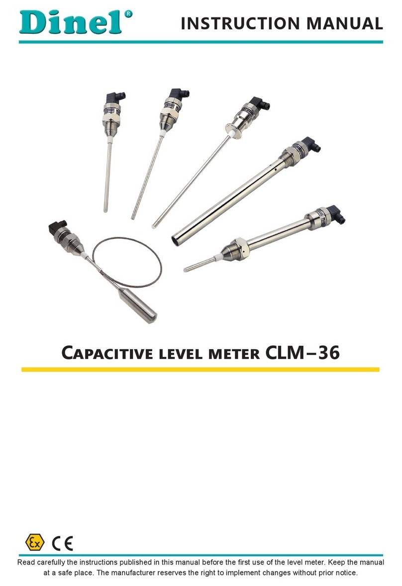
Capacitive level meters CLM – 36Capacitive level meters CLM – 36
INSTRUCTIONS MANUAL


2 . Basic description .................................................................................................................... 4
1 . Range of application ............................................................................................................... 4
3 . Variants of sensors ................................................................................................................. 5
4 . Dimensional drawing ............................................................................................................... 6
5 . Inuence of the tank shape on a linearity of measurement ..................................................... 8
6 . Installation and putting into operation ..................................................................................... 9
7 . Mechanical mounting .............................................................................................................. 9
8 . Electrical connection ............................................................................................................... 12
9 . Preparing of level meter for measuring ................................................................................... 14
10 . Settings ................................................................................................................................. 15
11 . Order code ............................................................................................................................ 17
12 . Correct specication examples ............................................................................................. 17
13 . Accessories ........................................................................................................................... 17
14 . Safety, protections, compatibility and explosion proof .......................................................... 18
15 . Use, manipulation and maintenance ..................................................................................... 19
16 . General, conditions and warranty ......................................................................................... 20
17 . Marking of labels ................................................................................................................... 21
18. Technical specications......................................................................................................... 23
19 . Table of relative permittivity .................................................................................................. 27
20 . Packaging, shipping and storage .......................................................................................... 28

CLM–36 © Dinel, s.r.o.
4
Capacitive level meters CLM® are designed for continuous level measurement of liquids,
powders and bulk-solid materials in vessels, tanks, sumps, containers, silos, etc. CLM consists
of the stainless steel housing with electronic module and the measuring electrode. The
electronic part converts the capacity into the current signal (4 ... 20 mA) or voltage signal (0 ...
10 V). Sensitivity (SPAN) and initial capacity compensation (ZERO) can be uently set.
Level meters are produced in the following performances: N – for non-explosive areas, NT –
high temperature for non-explosive areas, Xi – Explosion proof – intrinsically safe for hazardous
(explosive) areas and XiT - high-temperature conf. for explosive environments. CLM are oered
in variants with various types of process connection (thread, Tri-clamp).
Capacitive level meters are suitable for continuous level measurement of liquid and bulk-solid
materials. CLMs are resistant to any changes in the atmosphere above the surface (vacuum,
pressure, vapours, dust).
To ensure maximum safety of control processes, we have dened the following safety instructions
and information. Each instruction is labelled with the appropriate pictogram.
This symbol informs you about particularly important instructions for installation and operation of
equipment or dangerous situations that may occur during the installation and operation. Not observing
these instructions may cause disturbance, damage or destruction of equipment or may cause injury.
This symbol indicates particularly important characteristics of the device.
This symbol indicates helpful additional information.
All operations described in this instruction manual have to be carried out by trained personnel
or by an accredited person only. Warranty and post warranty service must be exclusively
carried out by the manufacturer.
Improper use, installation or set-up of the sensor can lead to crashes in the application.
The manufacturer is not responsible for improper use, loss of work caused by either direct
or indirect damage, and for expenses incurred at the time of installation or during the period
of use of the level sensors.

5
© Dinel, s.r.o. CLM–36
• CLM–36_–10 With uncoated rod electrode for level measurement of non-conductive
liquids (oils, diesel, petrol) and powder or bulk-solid materials (our, sand,
cement, plastic granulates, etc.).
Electrode length from 0.2 m to 5 m (for materials with a low permittivity
εr <10, the minimum electrode length is 0.5m).
• CLM–36_–11 With fully (PFA) coated rod electrode suitable for surface level measurement
of water and other electrically conductive liquids. Also suitable for polluted
liquids in metallic storage tanks, concrete sumps, etc.
Electrode length from 0.2 m to 3 m.
• CLM–36_–12 With fully (FEP) coated rod electrode suitable for surface level measurement
of water and other electrically conductive liquids. Also suitable for polluted
liquids in metallic storage tanks, concrete sumps, etc.
Electrode length from 0.2 m to 3 m.
• CLM–36_–20 With uncoated rod electrode and reference tube for accurate level meas-
urement of clean non-conductive liquids (oils, diesel, petrol).
Electrode length from 0.2 m to 3 m.
• CLM–36_–22 With fully FEP coated rod electrode and reference tube for surface level
measurement of electrically conductive liquids, (e.g. in plastic or glass storage
tanks) and where greater measurement accuracy is required. Electrode
insulation from FEP material.
Electrode length from 0.2 m to 3 m.
• CLM–36_–30 With uncoated stainless steel rope electrode and uncoated weight for
level measurement of bulk-solid materials (grains, sand, our, cement, etc.)
Shortened cable option.
Electrode length from 1 m to 20 m.
• CLM–36_–31 With uncoated stainless steel rope electrode and coated dynamic
anchorage for level measurement of bulk-solid materials in higher silos.
Electrode length from 1 m to 20 m.
• CLM–36_–32 With fully coated rope electrode and coated weight (rope insulation FEP,
weight insulation PTFE), for level measurement of electrically conductive and
non-conductive liquids.
Electrode length from 1 m to 20 m.

CLM–36 © Dinel, s.r.o.
6
CLM–36_–30CLM–36_–10, 11, 12 CLM–36_–20, 22
* type threads: M36x2; G1"
** for materials with a low permittivity (εr <10) the
minimum electrode length is E500.
thread *
High temperature variants
CLM–36_T
18056

7
© Dinel, s.r.o. CLM–36
CLM–36_–32 CLM–36_–31
Rope
electrode
Wall of container
(KV–31, PR–31)*
Spring
Anchor with
spherical joint
thread **
Housing with Tri-clamp
coupling
* Anchor welding cylinder KV–31 or Dust-tight
bushing PR–31 (see accessories)
** type of threads: Tri-Clamp CI50 (ø 50,5 mm)

CLM–36 © Dinel, s.r.o.
8
• In a curved tanks (most frequently horizontal cylinder)
capacity change during measuring of electrically non-
conductive material is non-linear.
• Linearity is done by reference tube (CLM – 36_–20, 22).
• In the tank with straight wall (for example vertical
cylinder) and with the sensor placed parallely
with the wall capacity change is linear.
FOR TYPE: CLM-36_-10, 11, 12
CLM-36_-30, 31, 32
FOR TYPE: CLM-36_-20, 22
FOR TYPE: All variants

9
© Dinel, s.r.o. CLM–36
• Level meters with coated electrode have protection cover at the end of electrode, which is
necessary take down before mounting.
• Level meters mount in vertical position to upper lid of tank or reservoir by steel welding ange
ON-36x2 (steel 11375), stainless steel welding ange NN-36x2 (stainless steel 1.4301), xing
nut UM-36x2 (stainless steel 1.4301) or Clamp ange.
• For mounting level meter to the metal tank or reservoir is not necessary to ground housing again.
• In case of installation in concrete sumps or silos it is properly to install level meter at metallic
auxiliary construction (console, lid, etc.) and then connect with metal all the time submerged
object, eventually with steel armouring.
• For measuring of material in plastic and glass vessels by level meter without reference
tube is necessary to connect grounding screw at housing with auxiliary electrode which is
xed by the appropriate method to the outer casing of vessels (or at inner wall). Material of
auxiliary electrode is necessary to choose with consideration to the working environment and
properties of measured material.
E- the length of electrode [mm] - the end of
the electrode has to be dipped min. 20 mm
below the lowest measured level
h- the distance from the bottom - min. 50 mm
a- the distance from the wall - min. approx. E/20
d- the diameter of auxiliary tube vessel - min.
40 + E/20 (smaller dimension has to be
discussed with producer)
auxiliary electrode
width = min. 30 mm
(necessary only for
non-metal vessels)
Fig. 1: Installation of level meter with rod electrode
Please follow next 3 steps:
METAL AND NON-METAL VESSESLS FOR TYPE: CLM-36_-10, 11, 12

CLM–36 © Dinel, s.r.o.
10
h - the distance from the bottom
- min. 50 mm with respect on
possibility of presence of heavy
fraction (water) in oil products
k - the distance from the wall -
optional
connection to the
armouring
E - The length of electrode - the lower end of the electrode has to be dipped - min. 20 mm below the lowest measured level
h - The distance from the bottom - min. 100 mm
a - The distance from the wall - at least E/20, as far as possible from the walls, to the middle between the wall and the vertical
inlet
concrete silo
metal tank
Fig. 2: Installation of level meter with reference tube
Fig. 3: Installation of level meter with rope electrode
VARIANTS WITH REFERENCE TUBE FOR TYPE: CLM-36_-20, 22
DEEP VESSELS, CONTAINERS AND SILOS FOR TYPE: CLM-36_-30, 32

11
© Dinel, s.r.o. CLM–36
E - the length of electrode [mm]
t - the length of the conduction
rod - approx. 500 mm
p - the length of the press
spring - approx. 200 mm
c - the distance from the centre
line of the silo - has to be as
minimal as possible
steel anchor welding
cylinder (mat. 11375) or
dust-tight bushing
to be welded into the
conical bottom wall
Fig. 4: Installation of rope electrode with anchor
ROPE ELECTRODE WITH ANCHOR FOR TYPE: CLM-36_-31

CLM–36 © Dinel, s.r.o.
12
The level meter is designed to be connected to supply unit or to controller through a cable with
the outer diameter of 6 ÷ 8 mm (recommended cross-section of cores 0.5 ÷ 0.75 mm2) by means
of connector which is standard part of CLM level meter. The diagram and the inside view of the
connector are shown in the gures. Disassemblable connector IP67 with a 5m long PVC cable
can be supplied as an above-standard accessory.
Procedure to connect the cable to the level meter:
1. Unscrew connector from the body of the level meter using a suitable screwdriver.
2. Use a at screwdriver to remove the inner part of the connector (screwdriver into the gap
marked by arrow).
3. Unscrew the cable gland and put the cable inside.
4. Connect the cable wires to the screw terminals as shown in Fig. 7 (current output 4-20 mA) or
Fig. 9 (voltage output 0-10 V). Tighten the terminals rmly.
5. Push the terminals back into the connector so that the terminal no. 3 is oriented toward the
cable entry. Tighten the cable gland.
6. Check the seal on the connector and connect the connector back to the body of the sensor.
Fig. 6: Connection scheme with current
output
Shielding
(GNYE)
+U (BN)
0V (BU)
Fig. 7: Connection scheme with
current output
Fig. 8: Connection scheme with voltage
output
Uout (BK) +U (BN)
Shielding
(GNYE)
0V (BU)
Fig. 9: Connection scheme with
voltage output

13
© Dinel, s.r.o. CLM–36
Electrical connection can only be made when de-energized!
The source of the power voltage must comprise of a stabilised safe low power source with
galvanic separation. In the event that a switch-mode power supply is used, it is essential
that its construction effectively suppresses common mode interference on the secondary
side. In the event that the switch-mode power supply is equipped with a PE safety terminal, it
mustbe unconditionally grounded! Spark-safe devices type CLM–36Xi(XiT) must be powered
from a spark-safe power source meeting the above-mentioned requirements.
Due to the possible occurrence of an electrostatic charge on the non-conductive parts of
the sensor, it is necessary to ground all sensors intended for use in environments with an
explosion hazard type CLM–36Xi(XiT). This can be performed by grounding el. conductive
tanks or el. conductive tank lids, and in the case of el. non-conductive tanks using and
grounding an auxiliary plate electrode PDE-27.
In the event that sensor is installed in an outdoor environment at a distance greater than 20
m from the outdoor switchboard, or from an enclosed building, it is necessary to supplement
the electrical cable leading to sensor with suitable over voltage protection.
In the event of strong ambient electromagnetic interference, paralleling of conductors with
power distribution, or for distribution to distances over 30 m, we recommend using a shielded
cable and grounding the shielding on the side of the power source.

CLM–36 © Dinel, s.r.o.
14
1. For access to the adjustment elements disconnect a connector and unscrew a nut (attention for
inside connecting wires). Connect the connector again.
2. Connect the level meter to the supply unit through milliammeter (controller, etc.).
3. Set the trimmer*1) 20 mA into the basic position (this position is set by producer):
a) Turn the trimmer totally right (clockwise).
b) Turn the trimmer back about 3 turns left (anti clockwise).
*1) The trimmers are without backstops - approx. 15 turns
Fig. 10: The top view on the internal electronic module
with current output (variant –I)
DIP switches
(for range select)
trimmer 4 mA
(for compensation
of initial capacity)
trimmer 20 mA
(for sensitive span
adjustment)
BU (-) BN (+)
GNYE
(Shielding)
brass tie
(for pull out of
electronic module)
DIP switches (for
range select)
trimmer 0 V
(for compensation of
initial capacity) trimmer 10 V
(for sensitive span
adjustment)
BU (-) BN (+)
GNYE
(Shielding)
BK
(Uout)
brass tie
(for pull out of
electronic module)
0V 10V
Fig. 11: The top view on the internal electronic module
with voltage output (variant –U)
Legend:
GNYE – green-yellow
BU – blue
BK – black
BN – brown

15
© Dinel, s.r.o. CLM–36
1. Empty the tank to the minimum level.
2. Set the DIP switches on the CLM to range*3) No. 2 (250 pF).
3. By a screwdriver turn the trimmer 4 mA and set the quiescent current of the level meter to
4 mA. Turning rightwards (clockwise) increases the current, turning leftwards decreases the
current. When it is impossible to set required current to 4 mA, then switch DIP switches to the
nearest higher range and set up the current 4 mA at that range.
4. Fill the tank to the maximum level. When it is impossible ll the tank to the maximum known
(or checkable) level. For the next settings calculate the output current using the next formula:
I out = 4 + (0,16 x level in %) [mA]
5. If the output current is less than 20 mA (or the calculated value of I out), set the DIP switch to the
lowest range No. 1. and continue to step 7. When the output current exceeds 20 mA, continue
on step 6.
6. Set the DIP switches step by step to higher ranges till the current is greater then 20 mA (or
calculated value of I out), then the current e.g. 21 mA*4) ows through the level meter. Trimmer
20 mA is still in basic position.
7. Then set the current of CLM by trimmer 20 mA onto 20 mA (or to the calculated value of I out
- see above).
8. To reach a maximum accuracy is useful to check the setting of 4 mA again (compensation of
initial capacity - quiescent current).
1. Empty tank to the minimum level.
2. By DIP switches on level meter set range*3) No. 2 (250 pF).
3. Use a screwdriver to turn the trimmer to 0 V and set the voltage at the output from the level
meter to 0 V. Turning rightwards (clockwise) increases the voltage, turning leftwards decreases
the voltage. When it is impossible to set required voltage to 0 V, then switch DIP switches to the
nearest higher range and set up the voltage 0 V at that range.
4. Fill the tank to the maximum level. When it is impossible ll the tank to the maximum known
(or checkable) level. For the next settings calculate the output voltage using the next formula:
U out = 0,1 x level in % [V]
5. If the output voltage is less than 10 V (or the calculated value of U out), set the DIP switchto the
lowest range No. 1. and continue to step 7. When the output voltage exceeds 10 V, continue
on step 6.
6. Set the DIP switches step by step to higher ranges till the voltage is greater then 10 V (or
calculated value of U out), then the voltage e.g. 10,5 V ows through the level meter. Trimmer
10 V is still in basic position.

CLM–36 © Dinel, s.r.o.
16
7. Then set the voltage of CLM by trimmer 10 V onto 10 V (or to the calculated value of U out -
see above).
8. To reach a maximum accuracy is useful to check the setting of 0 V again.
Table of ranges
No. Sensitivity 2) (C) Range 3) (R) Position of DIP switch
11) 20 pF 70 pF
230 pF 250 pF
350 pF 600 pF
4100 pF 1 200 pF
5150 pF 3 000 pF
6300 pF 7 000 pF
7500 pF 18 000 pF
81 000 pF 36 000 pF
Tables of recommended ranges depending on the medium and the type of level meter
Medium Plastic granulates (εrapproximately 2)
Type / electrode length 1 m 2 m 5 m 10 m 20 m
10, 30, 31 12234
Medium Flour, sand, grains (εrapproximately3)
Type / electrode length 1 m 2 m 5 m 10 m 20 m
10, 30, 31 22345
Medium Cement (εrapproximately 4)
Type / electrode length 1 m 2 m 5 m 10 m 20 m
10, 30, 31 22345
Medium Water (water solutions)
Type / electrode length 1 m 2 m 5 m 10 m 20 m
11, 12 345x x
22 3 4 xxx
32 34566
Medium Benzine, petroleum, diesel, oil (εrapproximately 2)
Type / electrode length 1 m 2 m 5 m 10 m 20 m
10, 30 12234
20 3 4 xxx

17
© Dinel, s.r.o. CLM–36
CLM-36
Nnon-explosive areas
NT high temperature performance
Xi for explosive environments
XiT high-temperature conf. for explosive environments
10 uncoated St. steel rod electrode, length 0,2 / 0,5 ... 5 m
11 fully coated St. steel rod electrode (PFA), length 0,2 ... 3 m
12 fully coated St. steel rod electrode (FEP), length 0,2 ... 3 m
20 uncoated St. steel rod electrode with reference tube, length 0,2 ... 3 m
22 coated St. steel rod electrode with reference tube (FEP), length 0,2 ... 3 m
30 uncoated St. steel rope electrode, length 1 ... 20 m
31 uncoated St. steel rope electrode with anchor, length 1 ... 20 m
32 suspension electrode with insulated cable (FEP) and insulated ballast (PTFE), length
1 ... 20 m
Mthread M36x2
Gthread G1"
Cl50 Tri-clamp (ø 50,5 mm)
Icurrent (4 ... 20 mA)
Uvoltage (0 ... 10 V)
Eelectrode length in mm
Kcable length in m
C N I
*1) Range No. 1 (70 pF) is very sensitive and we recommend to use it only at level meters with short electrode (approx. to 500
mm) and measured media with low permittivity
*2) Sensitivity - minimal capacity change of electrode to reach output range 4 ÷ 20 mA or 0 ÷10 V.
*3) Range = capacity of housing + activated electrode to reach output range 4 ÷ 20 mA or 0 ÷10 V. (For example.: uncoated
electrode 1000 mm immersion in fuel: 20 pF + 30 pF, coated electrode 1000 mm immersion in water: 20 pF + 500 pF)
*4) In case of short of electrode on housing or setting of a very sensitive range can caused to current restriction of level meter
on value max. 30 mA.
Note.: Types 10, 12, 30, 31, 32 in distance 250 mm from conducting wall.
Showned ranges are orientation. Exact range for existing conguration electrode / tank must be
set directly in application on mearured medium.

CLM–36 © Dinel, s.r.o.
18
CLM–36N–10–G–I E1000
(N) normal (for non-explosive areas); (10) uncoated St. steel rod electrode; (G) process connection thread G1"; (I)
current (4 ... 20 mA); (E1000) length electrode 1000 mm
CLM–36XiT–30–G–I E9750
(XiT) high-temperature conf. for explosive environments; (30) uncoated St. steel rope electrode; (G) process connec-
tion thread G1"; (I) current (4 ... 20 mA);(E9750) length electrode 9750 mm.
optional – for a surcharge (see catalogue
sheet of accessories)
• Connector with protection class IP67 (GAN–
DADE 7A) with 5 m cable (current output)
• Connector with protection class IP67 (GAN–
DAAE 7A) with 5 m cable (voltage output)
• Steel welding ange ON–36x2
• St. steel welding ange NN–36x2
• St. steel xing nut UM–36x2
• Anchor welding cylinder KV–31 (only
CLM–36–31)
• Dust-tight bushing PR–31(only CLM–
36–31)
standard (included in the level meter price)
• 1x of seal, other seals are on request
(PTFE, Al, etc.) *
• 1x connector socket
• 1x scr ewdr iver for adjustme nt (eac h 5 pcs)
* Pressure resistance - see the table in the
accessories datasheet in the "seals and
gaskets".

19
© Dinel, s.r.o. CLM–36
Level meter is equipped with protection against electric shock on the electrode, reverse polarity,
output current overload, short circuit and against current overload on output.
Protection against dangerous contact is provided by low safety voltage according to 33 2000-4-41.
Electromagnetic compatibility is provided by conformity with standards EN 55022 / B, EN 61326-1,
EN 61000-4-2 to -6.
Explosion proof CLM–36Xi(XiT) is provided by conformity with standards EN 60079-
0:2013+A11:2014, EN 60079-11:2012.
Explosion proof CLM–36Xi(XiT) is veried FTZÚ – AO 210 Ostrava – Radvanice: FTZÚ 02 ATEX
0235X.
A declaration of conformity was issued for this device in the wording of Act No. 90/2016 Coll., as
amended. Supplied electrical equipment matches the requirements of valid European directives for
safety and electromagnetic compatibility.
If the apparatus is used as device of Group II and with using of an approved power supply device,
which output parameters comply with required input parameters, it is necessary to have an galvanic
separation.
When used in zone 0 the present explosive atmosphere of air mixture and gases, vapours of mists
must comply with: -40°C ≤ Tamb ≤ 60°C; 0,08 Mpa ≤ p ≤ 0,11 Mpa.
Design CLM–36Xi can be used in zone 0 or zone 20. With design CLM–36XiT can be used in zone
0 and zone 20 only electrode part an head with electronics can be used only in zone 1 or zone 21.
Ambient temperature: Tamb = -40°C to +75°C
Temperature of measured medium according to design variant:
bar non-insulated electrode -40°C to +200°C
bar insulated electrode -40°C to +120°C
cable with insulated cable -40°C to +105°C
Maximum temperature of electrodes is equal to temperature of measured medium.
Maximum input parameters: Ui = 30 V; Ii = 132 mA; Pi = 0,99 W; Ci = 370 nF; Li = 0,9 mH

CLM–36 © Dinel, s.r.o.
20
The level meter does not require any personnel for its operation. Follow-up displaying device is
used to inform the technological entity operating personnel on the measured substance level height
during the operation.
MAINTAINCE OF LEVEL METER
Maintenance of this equipment consists in verication of integrity of the level meter and of the sup-
ply cable. Depending on the character of the substance measured, we recommend to verify at least
once per year the clarity of the ultrasound transducer emitting eld and to clean it, respectively. In
case any visible defects are discovered, the manufacturer or reseller of this equipment must be
contacted immediately.
It is forbidden to perform any modications or interventions into the CLM–36 level meter
without manufacturer's approval. Potential repairs must be carried out by the manufacturer
or by a manufacturer authorized service organization only.
Installation, commissioning, operation and maintenance of the CLM–36 level meter has to
be carried out in accordance with this instruction manual; the provisions of regulations in
force regarding the installation of electrical equipment have to be adhered to.
The level meter must be installed to prevent tensile overload of the rope electrode, see.
Specications.
REPLACEMENT OF DEFECTIVE ELECTRONIC MODULE
In case of detected electronic failure it is possible to replace the electronic module directly in pro-
cess place of level meter by following procedure:
1. Disconnect connector and unscrew a nut (attention for inside connecting wires).
2. Defective electronic module pick up by pliers onto brass tie and remove by tensile from housing
of level meter.
3. Check placing of white seal O-ring in housing and on pressure ring.
4. Repaired or new electronic module return back into housing of level meter and press down by
clamping ring (attention that contact pin will be a little open before insertion and contact springs
were not pressed under level of electronic casing).
5. Check placing of black seal O-ring on connector.
6. Screw a nut back (attention for inside connecting wires) and connect the connector.
contact pin
contact springs
brass tie
electronic module
cover
trimmers
Fig. 12: Side view of the electronic module
This manual suits for next models
8
Table of contents
Other Dinel Measuring Instrument manuals
Dinel
Dinel ULM-55N User manual
Dinel
Dinel ULM-53 series User manual

Dinel
Dinel ULM-53 series User manual
Dinel
Dinel ULM-53 series User manual
Dinel
Dinel ULM -70 Series User manual

Dinel
Dinel ULM -70 Series User manual
Dinel
Dinel CLM-70 User manual

Dinel
Dinel CLM-36 User manual

Dinel
Dinel CLM-36 User manual
Dinel
Dinel DLM-35 User manual
