LIMITATION OF LIABILITY..............................................................................1
DISCLAIMER OF WARRANTY.........................................................................1
SAFETY INSTRUCTIONS...............................................................................1
CARING FOR THE ENVIRONMENT BY RECYCLING........................................2
COPYRIGHT STATEMENT..............................................................................2
Table of Contents ...........................................................................................3
1. Description Of The Indoor Monitor................................................................5
1.1 Fittings .................................................................................................5
1.2 Specifications .......................................................................................5
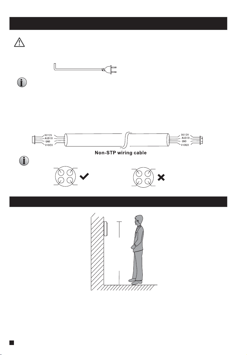
1.3 Note On Wiring Connection .............................. ................................6
1.4 Installation Process ...............................................................................6
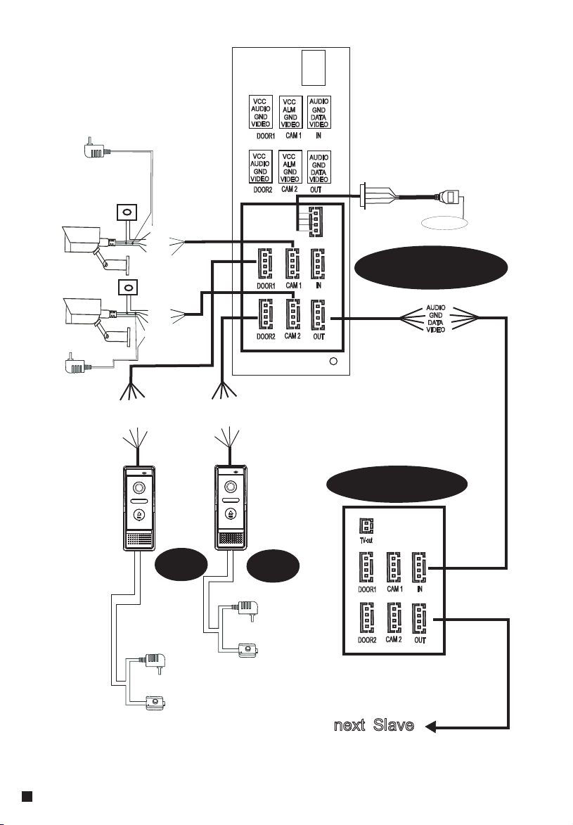
1.5 Wiring Diagram .....................................................................................7
1.6 Alarm Instructions .................................................................................9
1.7 Description On Indoor Monitor ................................................................9
1.8 Operation Introduction On Indoor Monitor ..............................................11
2.Menu Operations on Indoor Monitor.............................................................14
2.1Set System Parameters.........................................................................14
2.1.1 System-Language........................................................................14
2.1.2 System-Time...............................................................................15
2.1.3 System-Information.....................................................................15
2.1.4 System-Network..........................................................................16
2.1.5 System-Password........................................................................17
2.2 Set the Tone Parameters.......................................................................17
2.2.1 Ring-RIng Select..........................................................................17
2.2.2 Ring-Ring Volume ........................................................................18
2.2.3 Ring-Silence Mode .......................................................................18
2.3 Set the Mode of the indoor monitor.........................................................19
2.4 Set the alarm parameters......................................................................19
2.4.1 Alarm-CAM alarm.........................................................................20
2.4.2 Alarm-Alarm Record.....................................................................20
2.4.3 Alarm-Motion Detect.....................................................................21
2.5 Set the Color parameters......................................................................22
2.6 Playback.............................................................................................22
2.6.1 Files-Record Files........................................................................23
2.6.2 Files-Snapshot Files.....................................................................24
2.7 Device Connect--Through wired network or wireless network...................25
2.8 AP Mode........... ..................................................................................26
3. Web Browser Operation .............................................................................27
3.1 Running Environment...........................................................................27
3.2 Quick Setting.......................................................................................27
3.3 System Login ......................................................................................29
......
Table of ContentsTable of Contents
4. Port Forwarding......... .............................................................................31
5. Function Settings ....................................................................................32
5.1 Home.................................................................................................32
5.2 Media ................................................................................................33
5.2.1 Media--Video...............................................................................33
5.2.2 Media--OSD ................................................................................34
5.3 Parameters ........................................................................................34
5.3.1 Network--Basic Settings ...............................................................34
5.3.2 Network--DDNS ...........................................................................35
5.3.3 Network--E-mail...........................................................................35
5.3.4 Network--Wifi...............................................................................36
5.3.5 Network--Motion Detect................................................................37
5.4 System.............................................................................................. 37
5.4.1 System-Time Setting ...................................................................38
5.4.2 System-Initialize ........................................................................ 39
5.4.3 System-Device Info .....................................................................40
5.4.4 System-Storage Device................................................................40
5.4.5 System-System Log.....................................................................41
5.5 Logout...............................................................................................41
Appendix 1. Accessing the indoor monitor via Mozilla Firefox .........................42
Appendix 2. Accessing the indoor monitor via Google Chrome ........................42
Appendix 3 How to ensure reliable remote viewing of the indoor monitor through IE browser on Win 7/Win 8 64bit OS......44
34