NCTE 2000 Series User manual

Distribuito da: LUCHSINGER SRL
email: [email protected]
www.luchsinger.it
- All data without guarantee, except technical modification -
Page 1- 10
V18-03
NCTE torque sensors
Series 2000
Technical data
Measuring range in Nm (+/-): 2,5; 5; 7,5; 17,5; 75;
175; 250; 500
Rotational speed: ≤5.000 rpm
Accuracy: ≤±1 %
Temperature range: -40 °C to +85 °C
Protection class: IP50
Output signals: 0-5 V
Output frequency: 1.000 Hz
Your advantages
Made in Germany (Munich, Bavaria)
Delivery ex warehouse (< two weeks)
Best price-performance ratio
Integrated electronic (Plug & Play)
Contactless measurement system
Including 5 m cable and calibration certificate
The series 2000 is the most easy and affordable entry into torque measurement technology.
This series is mainly used in testing facilities, automation process, production lines e. g. end-of-line tests and
Research and Development.
Transmitted torque can be measured statically and dynamically in real time. Shaft is available as Round shaft
and Square shaft. Series 2000 offers a 0-5 V output signal.
The sensor is provided as a complete unit with integrated evaluation electronic, including 5 m cable,
keystones (Round shaft) and calibration certificate.
Short description
Optionally, the 2000 Series is available for explosive atmospheres
Conform to the EU ATEX directives for Zone 2
Additional zones on request

Page 2- 10
V18-03
NCTE torque sensors
Series 2000
Model
series 2200
round shaft
Unit
Nominal
torque
bidirectional
(+/-)
Load
bidirectional (+/-) in %1
Rotational
speed
[rpm]
100 - 130
130 - 200
> 200
Ø 9 mm
[Nm]
2,5
In
specification
Set up
opposite
directional
torque or
recalibration
by NCTE
To
recalibration
by NCTE
5.000
5
7,5
17,5
Ø 14 mm
75
Ø 19 mm
175
250
Ø 25 mm
500
Model
series 2100
square shaft
Unit
Nominal
torque
bidirectional
(+/-)
Load
bidirectional (+/-) in %
Rotational
speed
[rpm]
100 - 130
130 - 200
> 200
¼ inch
[Nm]
2,5
In
specification
Set up
opposite
directional
torque or
recalibration
by NCTE
To
recalibration
by NCTE
5.000
5
7,5
17,5
⅜ inch
75
½ inch
175
250
¾ inch
500
In case of an overload situation of the nominal torque it is possible to get the sensor back in specification. To
do so please set up the same overload situation in the opposite direction. This means in case of an overload
situation by 150 % positive load you can get the sensor back in specification by setting up a negative overload
of 150 %.
NCTE is able to recalibrate any sensor until ultimate torque.
1
By using feather keys the overload reduces to 170%.
Higher speed possible in clearance-free adaption.
Model series 2000
Distribuito da: LUCHSINGER SRL
email: [email protected]
www.luchsinger.it
- All data without guarantee, except technical modification -

Page 3- 10
V18-03
NCTE torque sensors
Series 2000
Model
series 2000
measuring range
Unit
Axial force [N]2
Lateral limit force [N]
Bending limit
moment [Nm]
2,5 und 5
[Nm]
1.000
20
2,5
7,5
1.000
30
3,7
17,5
1.000
100
12,5
75
2.600
300
41,7
175 und 250
4.000
500
89,5
500
7.000
800
176
Each type of irregular stress can only be permitted with its given limit value (bending moment, lateral force
or axial force, exceeding the nominal torque) if none of the others can occur. Otherwise the permitted limits
must be reduced. If for instance 30 % of the limited bending moment and also 30 % of the limited lateral
force are present, only 40 % of the limited axial force are permitted, provided that the nominal torque is not
exceeded.
2
Direct acting axial force on the shaft. If the force affects the snap ring, just 50 % of the force is permitted.
3
The accuracy class implies that taken separately both the linearity deviation as well as the rotational signal uniformity are either lower than or equal
to the value of the accuracy class.
4
%ME: related to a full scale measurement range.
5
Please check the exact data at the sensors calibration certificate.
No.
Model
Series 2000
Accuracy class3
1,0
Unit
Value
1
Linearity deviation incl. hysteresis
%ME4
≤±1,0
2
Rotational Signal Uniformity (RSU)
≤±1,0
3
Repeatability
≤±0,05
Output signal in general
Unit
Value
4
Frequency range, -3dB point,
Bessel characteristics
Hz
1.000
5
Analog signal
V
0 … 5
6
Signal at torque = Zero5
V
2,5
7
Signal at positive nominal torque5
V
4,5
8
Signal at negative nominal torque5
V
0,5
9
Calibration parameter (normed)5
V/Nm
Identification label
10
Output resistance
Ω
50
Load characteristics
Technical characteristics
Distribuito da: LUCHSINGER SRL
email: [email protected]
www.luchsinger.it
- All data without guarantee, except technical modification -

Page 4- 10
V18-03
NCTE torque sensors
Series 2000
6
Wiring connected.
Effect of temperature
Unit
Value
12
Zero point drift over temperature
%/10 K
≤0,5
13
Signal drift over temperature
within nominal temperature range
%/10 K
≤0,5
Power supply
Unit
Value
14
Supply voltage
VDC
6 … 15
15
Current consumption (max.)
mA
10
16
Start-up peak
mA
≤40
17
Absolute max. supply voltage
VDC
18
General information
Unit
Value
18
Protection class according to
EN 605296
IP
50
19
Reference temperature
°C
+15 … +35
20
Operational temperature range
°C
-40 … +85
21
Storage temperature range
°C
-40 … +85
22
Bearing operating hours
h
approx. 20.000
Nominal rated torque M (bi-
directional)
Nm
2,5
5
7,5
17,5
75
175
250
500
23
Weight
Rd
g
386
392
400
685
856
1.230
Sq
395
401
414
652
754
878
24
Moment of inertia
Rd
g mm2
597
662
1.073
4.922
19.126
79.754
Sq
582
648
904
3.339
13.294
57.770
Distribuito da: LUCHSINGER SRL
email: [email protected]
www.luchsinger.it
- All data without guarantee, except technical modification -

Page 5- 10
V18-03
NCTE torque sensors
Series 2000
Do not loosen or tighten the mounting nuts of the socket and the lock screws
Dimensions
Round shaft
nominal torque [Nm]
Square shaft
nominal torque [Nm]
Ø 9 mm
Ø 14 mm
Ø 19 mm
Ø 25 mm
1/4 inch
3/8 inch
1/2 inch
3/4 inch
Nominal torque
[Nm]
2,5 - 5 -
7,5 - 17,5
75
175 - 250
500
2,5 - 5 -
7,5 - 17,5
75
175 - 250
500
A
125
139
179
220
95,5
107
123,5
146
B
70
70
70
87
70
70
70
87
C
27,5
34,5
54,5
66,6
9,5
13
18,5
29,6
D
9k6
14k6
19k6
25k6
-
-
-
-
E
40
50
50
60
40
50
50
60
F
-
-
-
-
16
24
35
29,6
G
8
8
8
10,5
8
8
8
10,5
H
5
5
5
2
5
5
5
2
K
-
-
-
-
12
18
24
33,5
L
23
30
50
≙C
-
-
-
-
M
43,9
43,9
43,9
61,4
43,9
43,9
43,9
61,4
N
15
18
18
19
15
18
18
19
P
37
47
47
57
37
47
47
57
S
1,5
1,5
1,5
1,5
1,5
1,5
1,5
1,5
Dimensions
Distribuito da: LUCHSINGER SRL
email: [email protected]
www.luchsinger.it
- All data without guarantee, except technical modification -

Page 6- 10
V18-03
NCTE torque sensors
Series 2000
Dimensions keyway [mm]
Keystones
Round
shaft
Width
Depth
Length
Height
Length
Amount
Ø 9 mm
3
1,8
18,5
3
18
1
Ø 14 mm
5
3
25,5
5
25
1
Ø 19 mm
6
3,5
45,5
6
45
1
Ø 25 mm
8
4
50,5
7
50
2
Connector
Power supply and outputs
The output Vref is a constant 2.5 V and represents the virtual zero
point for direct +/- torque measurement.
Type
Binder series s712-M9 connector IP67
colour coding according to DIN 47100
Pin
Colour
Pin
Value
1
White
Supply Voltage VCC
6 V –15 V
2
Brown
Signal Output analogue
-
3
Black
Ground GND
-
4
Blue
Not used
-
5
Grey
Reference Voltage Vref
2,5 V
Connection example:
Connection for measurement between 0,5 … 4,5 V
e.g. 2.5 V equals to approx. 0 Nm.
Grey and blue wires are not in use.
Connection for measurement between –2,0 … + 2,0 V
e.g. 0 V equals to approx. 0 Nm.
Blue wire is not in use.
Connection plan
Keystone
Distribuito da: LUCHSINGER SRL
email: [email protected]
www.luchsinger.it
- All data without guarantee, except technical modification -

Page 7- 10
V18-03
NCTE torque sensors
Series 2000
Series 2000 accuracy 1 %
Price
Series 2100 square shaft
Series 2200 round shaft
Measurement range
2,5
Nm including 5 m cable and calibration certificate
5
Nm including 5 m cable and calibration certificate
7,5
Nm including 5 m cable and calibration certificate
17,5
Nm including 5 m cable and calibration certificate
75
Nm including 5 m cable and calibration certificate
175
Nm including 5 m cable and calibration certificate
250
Nm including 5 m cable and calibration certificate
500
Nm including 5 m cable and calibration certificate
Please feel free to contact your LUCHSINGER sales team for additional information. E
By Series 2000 please keep in mind to order it with sensor bracket (at accessories) as the housing has no
treats.
Series 2000 - Accessories
Price
Sensor bracket
1
2,5 –17,5 Nm (order number: 400006-ATS100)
2
75 –250 Nm (order number: 400006-ATS101)
NCTE Readout Unit works with all NCTE Sensors
A
Torque sensor input: Voltage output 0-5 V and 0-10 V
Order number: 400010-ATS001
1 angle encoder input, A/B
USB interface, Windows software included
SD card slot
X
Customized couplings (only for round shaft), price on request
NCTE Readout Unit is also available for a current output 4-20 mA torque sensor input.
Order options
Distribuito da: LUCHSINGER SRL
email: [email protected]
www.luchsinger.it
- All data without guarantee, except technical modification -

Page 8- 10
V18-03
NCTE torque sensors
Series 2000
The series 2000 is the most easy and affordable entry into torque measurement technology.
This series is mainly used in testing facilities, automation process, production lines e. g. end-of-line tests and
Research and Development.
Transmitted torque can be measured statically and dynamically in real time. Shaft is available as Round shaft
and Square shaft. Series 2000 offers a 0-5 V output signal.
The sensor is provided as a complete unit with integrated evaluation electronic.
General
Please read the instructions carefully before using it for the first time and only use the product for the
intended purpose. Keep this manual for future reference to avoid any incorrect use. The instruction manual
can also be downloaded as a PDF file under the following link: http://www.ncte.com/service/downloads/,
Local representative
The local representative of the torque sensor series 2000 is:
LUCHSINGER SRL
Via Bergamo, 25
24035 Curno (BG)Germany
Tel.: +39 035 462678
Fax: +39 035 462790
EU directives and standards
The series 2000 is compliant with the European Union directives and the European Standards listed in
this document. Further requirements are to be requested from the manufacturer.
Scope of delivery
The torque sensor set consists of the sensor series 2000 (signal pick-up and signal processing integrated
into sensor housing), one connecting cable 5 m with a soldered plug (binder plug no. 99-0426-10-08), key
stones (round shaft) or square sleeve (Square shaft) and the calibration certificate.
Datasheets and instruction manuals are available at www.ncte.com.
Intended Use
Use the product only as described in the instruction manual. Any other use is considered as improper and
may result in property damage or even personal injury. The manufacturer assumes no liability for damage
caused by improper or incorrect use.
Installation and removal
Make sure to install the sensor shafts exactly with the proper aligned connecting shafts. The key
stone adapter/square endings of the connecting shafts are to be attached forceless to the corresponding
ones of the sensor. No external axial force should be on the housing of the sensor from distortion. A
maximum cable length of 5 m must not to be exceeded. Using a cable or connector other than supplied by
NCTE, or a similar cable that is of a different length may affect the overall performance of the sensor.
Do not remove the shaft with torque applied to the sensor.
Instruction manual
Distribuito da: LUCHSINGER SRL
email: [email protected]
www.luchsinger.it
- All data without guarantee, except technical modification -

Page 9- 10
V18-03
NCTE torque sensors
Series 2000
Interface description
Mechanical connection:
The key stone adapters on both ends of the measurement shaft are intended for torque transmission.
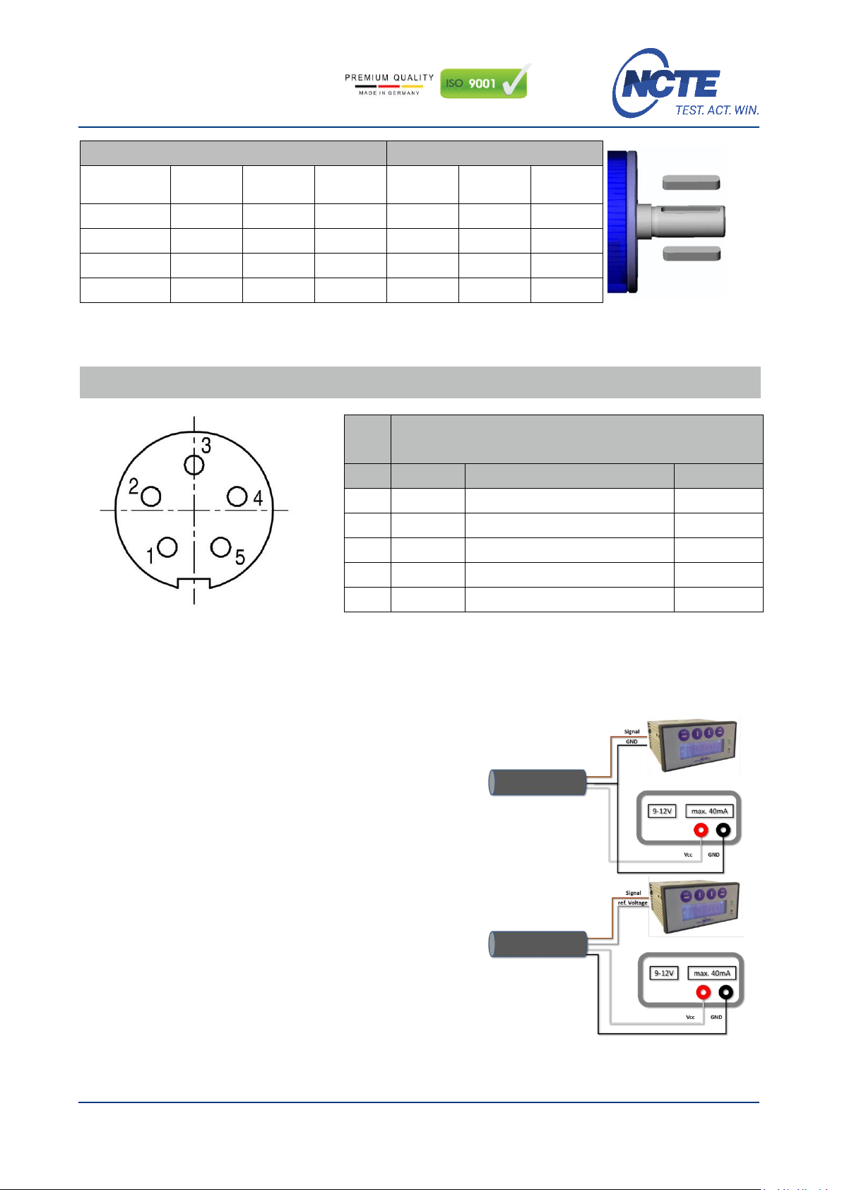
Electrical connector:
On the sensor housing there is a 8-pin socket for the power supply and the signal output (see chapter
connection plan).
Operation (in regular case or in optimal case)
Optimal measurement parameters can be achieved if the sensor is applied in accordance to the specification.
By compliance with the specification the sensor works generally trouble-free and maintenance-free.
Irregular operation, measures against disturbance
The mechanical overload on the sensor (e. g. exceeding of maximum allowed torque or severe vibrations)
may cause damage to the sensor and in consequence the incorrect signal output. In such cases please do
not open the sensor. Contact LUCHSINGER directly for assistance.
Commissioning
After sensor installation pay attention to the following:
The sensor may only be operated with a shielding.
Switch on the power supply unit and check the supply voltage. Peak voltage must be avoided! Be
sure to verify the power supply voltage before connecting the sensor!
Connect the sensor to the power supply unit by using the delivered cable.
Connect the sensor output to a high-resistance device such as an A/D converter, oscilloscope, pc
measurement board. The sensor should be in mechanical unloaded state while connecting it.
Shaft coating
The shafts are protected on both sides with a film of anticorrosion wax. We recommend to leave the
protection permanent. As far as technologically needed, the coating can be removed with spirit / ethanol
Handling and transportation
By handling, storage and transportation keep the sensor away from magnetic or electromagnetic fields which
may exceed the maximal intensity defined from EMC (chapter technical characteristics) for instance
degaussing machines.
Precautions
Do not open the sensor housing under any circumstances.
Do not remove or loosen the locking rings on the shaft ends.
Do not loosen or tighten the flange-mounting nut of the socket-connector (chapter dimensions).
Use only a separate power supply for the sensor.
Use the sensor only according to the specification (chapter technical characteristics).
Maintenance and overhaul
As part of your testing and measuring equipment management, we recommend regular checking of your
testing and measuring equipment. Please also observe the corresponding standards and guidelines.
Recommended NCTE maintenance plan
Recalibration
12 month
Control of wiring, plug and shaft
12 month
Distribuito da: LUCHSINGER SRL
email: [email protected]
www.luchsinger.it
- All data without guarantee, except technical modification -

Page 10 - 10
V18-03
NCTE torque sensors
Series 2000
Repairs
Repairs must be carried out exclusively by employees of NCTE AG. The sensor must be sent to the NCTE AG
together with an RMA formula (Return Merchandise Authorization). You will receive an RMA formula via the
NCTE service-hotline.
Disposal
Dispose the product and all associated components via an authorized waste disposal company. Please
observe the currently applicable regulations. If in doubt, ask your disposal centre for environmentally friendly
disposal.
Distributore italiano:
Telefono: +39 035 462678
email: [email protected]
www.luchsinger.it
Distribuito da: LUCHSINGER SRL
email: [email protected]
www.luchsinger.it
- All data without guarantee, except technical modification -
Other manuals for 2000 Series
1
This manual suits for next models
2
Table of contents
Other NCTE Accessories manuals
Popular Accessories manuals by other brands

BETTCHER INDUSTRIES
BETTCHER INDUSTRIES Whizard Power Knife 109496 Operator's manual

Badger Meter
Badger Meter SDI Series Installation & operation manual

Greengate
Greengate PPS-4 Installation sheet

brennenstuhl
brennenstuhl Premium-Line Comfort Switch Plus operating instructions

Leviton
Leviton 279-PM Installation

Wyebot
Wyebot WIS4200 quick start guide