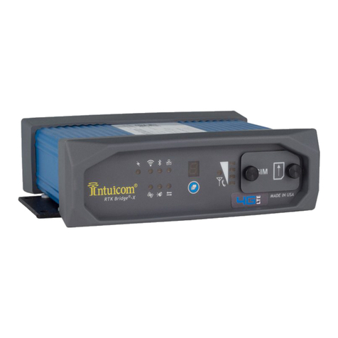
Intuicom RTK Bridge-X User manual

Intuicom, Inc.
4900 Nautilus Ct. N., Ste. 100
Boulder, CO 80301
(303) 449-4330
www.intuicom.com
RTK Bridge®-X
Integration with:
Trimble®XCN-2050™
Installation Guide

Version 1.0 1 Intuicom, Inc.
This Document is for internal use by Intuicom Employees or by Resellers and Distributors who
are authorized and/or licensed to install Intuicom products. No part of this document may be
reproduced or transmitted in any form or by any means, electronic or mechanical, or for any
purpose without the express written permission of Intuicom Inc.
© 2000-2016 Intuicom Incorporated. All rights reserved.
Intuicom reserves the right to make changes to this document without notice. Unless otherwise
agreed to in writing, Intuicom assumes no responsibility or liability for the use of this document
or for the infringement of any copyright or other proprietary right and Intuicom shall deem
nothing contained in this document a warranty or guarantee.
Intuicom and RTK Bridge are registered trademarks of Intuicom, Inc.
Other product names mentioned in this guide may be copyrights, trademarks, or registered
trademarks of their respective companies and are hereby acknowledged.

Section 1: Installation Requirements
Version 1.0 2 Intuicom, Inc.
Overview
The Trimble®XCN-2050™receiver is typically configured to accept CMR format RTK
corrections from an Intuicom RTK Bridge®-X, which in turn has been configured to connect to a
GPS/GNSS reference network. The intended audience for this document are dealers or
integrators familiar with the XCN-2050 and access to its set-up menus, as well as general
familiarity with the Intuicom RTK Bridge®–X. The Intuicom RTK Bridge®–X User Guide
covers the steps necessary for its configuration.
1 Requirements for Installation
1.1 Required Information
In order to operate an Intuicom RTK Bridge®–X, you are required to have the necessary
information to access and log in to the Real-Time Network. This information is entered
into the RTK Bridge®–X and stored in a profile. More details on setting up an RTK
Bridge®–X is available in the RTK Bridge®-X User Guide. Required information for the
Profile configuration include:
IP Address
TCP Port
NTRIP Mountpoint Name
Username and Password for access to the real-time GPS/GNSS Network
1.2 Required Equipment
1.2.1 Intuicom Equipment and Accessories
1. Intuicom RTK Bridge®–X with activated data provider account (Verizon, AT&T,
etc.)
2. Intuicom RTK Bridge®–X to XCN-2050 data/power cable: [P/N: XRTKCAB-
DD6]
3. Intuicom RTK Bridge®–X Bluetooth Receiver: [P/N: XRTK-BT-T]
4. Intuicom RTK Bridge®–X Cellular/GPS antenna/cable:
[P/N: FIP4-MMDM-MM (magnetic mount)]
1.2.2 Other Equipment and Accessories
5. Trimble XCN-2050 Receiver with RTK (CMR) option enabled and Port D available
6. Trimble XCN-2050 Data Cable and source of power for Trimble XCN-2050 (or any
cabling system typically used to run the Trimble XCN-2050 for configuration)
7. Trimble EXP-100 Port Expander

Section 2:Installation Instructions
Version 1.0 3 Intuicom, Inc.
2 Installation Instructions
Below (Diagram 1) are the components for the recommended installation of the Intuicom RTK
Bridge®–X utilizing the equipment noted above.
Diagram 1
2.1 Configuration
Configure the Intuicom RTK Bridge®–X to connect to GPS/GNSS Reference
network and obtain CMR/CMR+ correction data stream from an appropriate single
reference station, or as a VRS.
Configure the resulting RTK correction data to be output at a known baud rate (a
baud rate of 38400 is recommended).
Confirm GPS and cellular antenna (typically a combined antenna with two coaxial
cables with TNC connectors) are connected and placed where they have good sky
view and good cellular signal.
Configure the pinout on the Deutsch connector on the RTK Bridge®–X to FMX
data/power cable to match the appropriate pin-out. See Pin-out Diagram 1 on the
following page.

Section 2:Installation Instructions
Version 1.0 4 Intuicom, Inc.
Pin-out Diagram 1
Deutsch
Cable Color
Signal
FMX D-Port
3
Red
Power
9
6
Green
Receive (from RTK Bridge®-X to
remote device)
3
1
White
Xmit (to RTK Bridge®-X from
remote device)
4
4
Black
Power Ground
8
4
Brown
Signal Ground
5
1
89101112
65432
7
Using the Intuicom RTK Bridge®–X to XCN-2050 data/power cable (XRTKCAB-
DD6), connect the RTK Bridge®–X data port/Bluetooth Receiver to the EXP-100 port
expander that is connected to the TM200 receiver.
Apply power and turn on the XCN-2050.
Deutsch connector
(DTM06-12S)
pinout

Section 2:Installation Instructions
Version 1.0 5 Intuicom, Inc.
Open the FM-1000+ [FmX Plus] app to configure the RTK options.
Select the Settings tab,

Section 2:Installation Instructions
Version 1.0 6 Intuicom, Inc.
Then select System [System] from the left column, then click-on Setup on the upper-
right.
Enter the Administration Password (assigned by Trimble) to setup the RTK
Configuration (if prompted).

Section 2:Installation Instructions
Version 1.0 7 Intuicom, Inc.
Select Port Setup from the left column, and then click on Setup on the upper right.
Go to the second field on the right side of the screen below titled, “Receiver EXP-
100”. In the drop-down menu to its Right, you will discover that the Receiver’s Serial
number has been pre-populated in the drop-down menu. Select the Serial number
present and click on OK.

Section 2:Installation Instructions
Version 1.0 8 Intuicom, Inc.
Click on OK to exit back to the Configuration page, below.
Click on OK again to return to the Configuration page below

Section 2:Installation Instructions
Version 1.0 9 Intuicom, Inc.
Select GPS Receiver from the left column, and then click on Setup in the upper-right.
The default setting for the corrections will be Autonomous .

Section 2:Installation Instructions
Version 1.0 10 Intuicom, Inc.
Using the pull-down menu, change this setting to CenterPoint RTK .
Ensure the Antenna Selection is set to the appropriate type from the pull-down
menu; for this Installation Guide, Ag25 was used. Now click OK on the lower-right to
confirm your settings.
NOTE: Using the RTK Bridge®-X, you do not require the use of an external radio so
simply click on OK if the following screen appears.

Section 2:Installation Instructions
Version 1.0 11 Intuicom, Inc.
Click on GPS Receiver from the left column, then click on the Diagnostics to the right to
configure the EXP-100 for Port D.
On the Autopilot GPS Status page, click on AgRemote, in the lower-left corner.

Section 2:Installation Instructions
Version 1.0 12 Intuicom, Inc.
NOTE: In AgRemote, you will toggle through the screens using the up/down arrows and the
right/left arrows to transition through the settings and screens to configure Port D.
In AgRemote, click on the right arrow (>) to get to the Configure screen. Now click
on the down arrow (v) to Enter your selection.
Click on the right arrow (>) to get to Port D Config and confirm your selection by
clicking on the down arrow (v).

Section 2:Installation Instructions
Version 1.0 13 Intuicom, Inc.
AgRemote’s default correction source is TSIP and a baud rate of 38400. To change
this to CMR you will need to use the arrows to navigate the available options.
Use the right arrow (>) to move the cursor over to the ‘T’ in TSIP.
Click on the down arrow (v) to change the setting to CMR.
Using the right arrow (>) again, scroll over to the ‘T’ in TSIP visible on the screen.
Using the down arrow (v), change the setting to None.
Press the () button to save your settings, the cursor will disappear.

Section 2:Installation Instructions
Version 1.0 14 Intuicom, Inc.
When the cursor stops blinking press the up arrow (^), to get to the screen below.
Press the () to return to the Port D Config screen.

Section 2:Installation Instructions
Version 1.0 15 Intuicom, Inc.
Using the left arrow (<), scroll through the screens until you get to the following
screen.
Press the up arrow (^), to return to the Configuration screen.

Section 2:Installation Instructions
Version 1.0 16 Intuicom, Inc.
Press on the left arrow (<) to scroll through to the Status screen (below):
The above screen is intended to confirm that your Intuicom RTK Bridge®-X is correctly
configured and its antennas are connected and within cellular coverage. The main status
view (above) reports that it is receiving RTK corrections. CMR: indicates the percentage of
packets being received; and A: indicates the age, in seconds, of the corrections. The lower the
number, the better. We like to see the correction age at 2.0 seconds or less for desired
accuracy.
The ‘R’ in the top line indicates whether your RTK correction is fixed or floating. A capital
‘R’ indicates an RTK Fix; and a lower case ‘r’ indicates RTK Float.
Your Trimble XCN-2050 is now configured and integrated for use with your Intuicom RTK
Bridge®-X.
For Technical Support of the RTK Bridge®-X, Intuicom recommends
“Intuicom Remote Support”. Please contact Intuicom, or visit
http://www.intuicom.com/gps-gnss-products/intuicom-remote-support
for details on this real-time remote support program.
or call us at 303.449.4330.
Other manuals for RTK Bridge-X
9
Table of contents
Other Intuicom Network Hardware manuals
Popular Network Hardware manuals by other brands

Matrix Switch Corporation
Matrix Switch Corporation MSC-2HD2416S product manual

Artison
Artison Astronics Talon Instruments T940 64-Channel Digital Resource... user manual

Intercoax
Intercoax HPS-1008 quick start guide

Lenovo
Lenovo ThinkCentre M90n-1 Setup guide

Dot Origin
Dot Origin VTAP Series Integration guide

CheckMK
CheckMK Rail2 Mark I quick start

ADTRAN
ADTRAN Fractional T1 Tandem Channel Unit FT1-TDM Specifications

Venue
Venue Tag quick start guide

Flowmon
Flowmon P1GCCBPv2 quick start guide

APM
APM ABR-2502 specification

ZyXEL Communications
ZyXEL Communications FiberHome AN5516-06 Hardware description

Andrew
Andrew CommScope ION-M17P Advanced manual