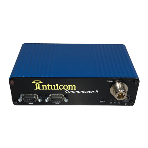
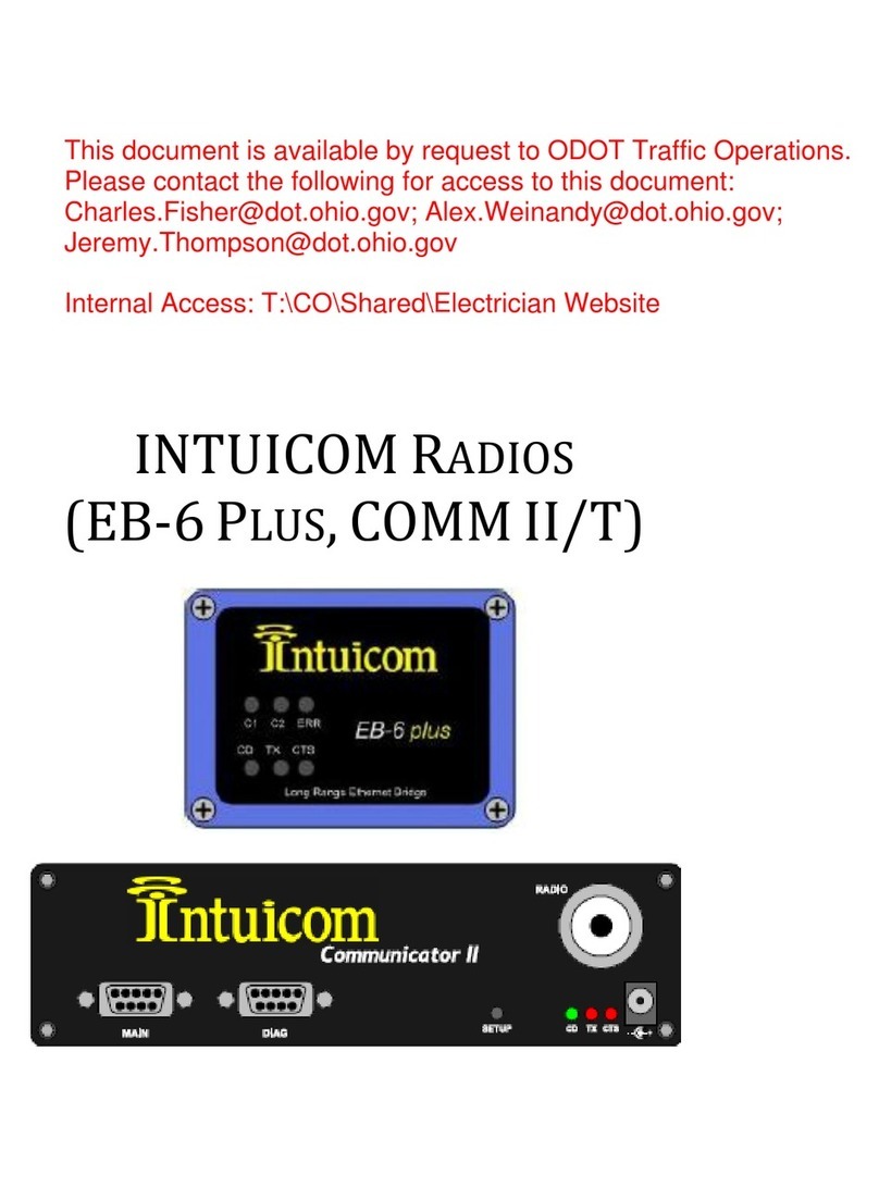
Intuicom Communicator User manual

Intuicom, Inc.
1880 South Flatiron Court
Boulder, CO 80301
(303) 449-4330
www.intuicom.com
Intuicom®
CommunicatorTM
Wireless Data Transceiver
User Manual

Intuicom CommunicatorTM User Manual
Revision A © 2001 Intuicom, Inc. i September 2001
This manual is for use by purchasers and other authorized users of the Intuicom
CommunicatorTM Wireless Data Transceivers. No part of this document may be reproduced or
transmitted in any form or by any means, electronic or mechanical, or for any purpose without
the express written permission of Intuicom Inc.
© 2001 Intuicom Incorporated. All rights reserved.
Intuicom reserves the right to make changes to this manual without notice. Unless otherwise
agreed to in writing, Intuicom assumes no responsibility or liability for the use of this manual or
for the infringement of any copyright or other proprietary right and Intuicom shall deem nothing
contained in this manual a warranty or guarantee.
Intuicom, WiGate, Intuicom CommunicatorTM, and Intuicom SmartGPS TrackerTM/SurveyorTM
are Trademarks of Intuicom, Inc.
Other product names mentioned in this manual may be copyrights, trademarks, or registered
trademarks of their respective companies and are hereby acknowledged.
Parts of this manual have been reproduced with permission from Copyrighted material of
Freewave Technologies, Inc. or other system component suppliers.

Intuicom CommunicatorTM User Manual
Revision A © 2001 Intuicom, Inc. ii September 2001
This device complies with part 15 of the FCC
rules. Operation is subject to the following two
conditions: 1) This device many not cause
harmful interference and 2) this device must
accept any interference receiver, including
interference that may cause undesired
operation.
This device must be operated as supplied by
Intuicom, Inc. Any changes or modifications
made to the device without the express written
approval of Intuicom, Inc. may void the user’s
authority to operate the device.
This product is licensed by The United States.
Diversion contrary to U.S. law is prohibited.
Shipment or re-export of this product outside
The United States may require authorization by
the U.S. Bureau of Export Administration.
Please contact Intuicom Inc. for assistance and
further information.

Intuicom CommunicatorTM User Manual
Revision A © 2001 Intuicom, Inc. iii September 2001
Table of Contents
1Quick Start............................................................................................................................. 1
2Quick Start on a Multipoint System.................................................................................... 2
3Tuning Transceiver Performance........................................................................................ 3
4Operation Mode Selections................................................................................................... 6
4.1 (0) Point-to-Point Master................................................................................................ 6
4.2 (1) Point-to-Point Slave .................................................................................................. 6
4.3 (2) Point-to-Multipoint Master........................................................................................ 6
4.4 (3) Point-to-Multipoint Slave .......................................................................................... 6
4.5 (4) Point-to-Point Slave/Repeater................................................................................... 7
4.6 (5) Point-to-Point Repeater............................................................................................. 7
4.7 (6) Point-to-Point Slave/Master Switchable ................................................................... 7
4.7.1 Using Mode 6 to call a transceiver not listed in the Call Book............................... 9
4.8 (7) Point-to-Multipoint Repeater .................................................................................... 9
5Multipoint Operation.......................................................................................................... 10
5.1 Theory of Operation...................................................................................................... 10
5.2 Installing Multipoint Systems........................................................................................ 10
5.3 Overlapping Multipoint Systems ................................................................................... 11
5.4 Setting Multipoint Parameters ...................................................................................... 11
5.4.1 (0) Number Repeaters ........................................................................................... 11
5.4.2 (1) Master Packet Repeat ...................................................................................... 11
5.4.3 (2) Max Slave Retry .............................................................................................. 13
5.4.4 (3) Retry Odds....................................................................................................... 13
5.4.5 (4) DTR Connect................................................................................................... 14
5.4.6 (5) Repeater Frequency ......................................................................................... 14
5.4.7 (6) NetWork ID ..................................................................................................... 15
5.4.8 (8) MultiMaster Synch .......................................................................................... 15
5.4.9 (9) 1 PPS Enable/Delay......................................................................................... 15
5.4.10 (A) Slave/Repeater ................................................................................................ 16
5.4.11 (B) Diagnostics...................................................................................................... 16
5.4.12 (C) Subnet ID ........................................................................................................ 16
5.4.13 (D) Radio ID.......................................................................................................... 19
6Baud Rate Selections........................................................................................................... 20

Intuicom CommunicatorTM User Manual
Revision A © 2001 Intuicom, Inc. iv September 2001
6.1 Set Baud Rate ................................................................................................................ 20
6.2 Data Word Length and Parity....................................................................................... 21
6.3 ModBus RTU................................................................................................................. 21
7Call Book Selections............................................................................................................22
7.1 Edit Call Book ............................................................................................................... 22
7.2 Entering or Modifying numbers in the Call Book......................................................... 23
7.3 Programming The Call Book in Multipoint Systems..................................................... 24
8Radio Transmission Parameters........................................................................................ 25
8.1 (3) Edit Radio Transmission Characteristics................................................................ 25
8.2 FreqKey.........................................................................................................................26
8.2.1 900MHz................................................................................................................. 26
8.2.2 2.4GHz .................................................................................................................. 28
8.3 (1) Max Packet Size and (2) Min Packet Size ............................................................... 29
8.4 (3) Xmit Rate ................................................................................................................ 32
8.5 (4) RF Data Rate .......................................................................................................... 32
8.6 (5) RF Xmit Power ........................................................................................................ 33
8.7 (6) Slave Security ..........................................................................................................33
8.8 (7) RTS to CTS............................................................................................................... 33
8.9 (8) Retry Time Out......................................................................................................... 34
8.10 (9) Lowpower Mode ...................................................................................................... 35
9Radio Statistics .................................................................................................................... 37
9.1 Average Noise Level...................................................................................................... 37
9.2 Average Signal Level..................................................................................................... 37
9.3 Overall Rcv Rate (%) .................................................................................................... 38
9.4 Number of Disconnects ................................................................................................. 38
9.5 Radio Temperature........................................................................................................ 38
10 Transceiver Location ...................................................................................................... 39
11 Front Panel LEDs............................................................................................................ 40
12 Using an External Antenna ............................................................................................ 42
12.1 Antenna Alignment ........................................................................................................ 44

Intuicom CommunicatorTM User Manual
Revision A © 2001 Intuicom, Inc. v September 2001
12.2 Setup procedure............................................................................................................. 44
12.3 Point to multipoint procedure ....................................................................................... 44
13 RS232 Pin Assignments .................................................................................................. 45
14 DGRO Small Footprint Series Pinout ........................................................................... 47
15 DGR-115W Waterproof Enclosure Pinout................................................................... 48
16 Data Communications Settings...................................................................................... 49
17 Establishing Data Communication Links ..................................................................... 50
18 Other Settings ..................................................................................................................54
18.1 Baud Rate ...................................................................................................................... 54
18.2 Setup Timeout................................................................................................................ 54
19 Technical Specifications.................................................................................................. 55
20 Troubleshooting............................................................................................................... 57
21 Antenna Installation Drawing........................................................................................ 60
22 Warranty Statement ....................................................................................................... 61

Intuicom CommunicatorTM User Manual
Revision A © 2001 Intuicom, Inc. vi September 2001
List of Figures
Figure 3-1: Initial Menu .................................................................................................................. 4
Figure 3-2: Communicator Operation Mode Menu ........................................................................ 5
Figure 5-1: Multipoint Parameters ................................................................................................ 13
Figure 5-2: Multipoint Subnet Diagram........................................................................................ 18
Figure 6-1: Baud Rate, Word Length & Modbus ......................................................................... 20
Figure 7-1: Call Book Menu ......................................................................................................... 23
Figure 8-1: Radio Parameters Menu ............................................................................................. 25
Figure 8-2: Hop Table Parameters ................................................................................................ 26
Figure 8-3: Frequency Key and Hop Table Options, 2.4 Ghz ...................................................... 29
Figure 15-1: Waterproof Connector.............................................................................................. 48

Intuicom CommunicatorTM User Manual
Revision A © 2001 Intuicom, Inc. 1 September 2001
1 Quick Start
This manual covers the operation of both the 900 MHz and 2.4 GHz Intuicom CommunicatorTM
spread spectrum transceivers. For the most part operation of the products is identical, where
operating differences exist every effort has been made to clearly identify which product family is
being referred to.
When purchased as a pair the Intuicom Wireless Data Transceivers are shipped from the factory
pre-configured to operate together in point-to-point applications. The Transceivers are preset for
high-speed data communications and to communicate only with each other.
The Communicator will potentially operate in virtually any environment where RS232 data
communications occur. The transceivers function as a 9-pin null modem cable. If the
Communicator is to be used in an application where a null modem cable is used (such as
communication between two computers), then the communicator can be connected directly. If
the Communicator is to be used to replace a straight-through RS232 cable, then a null modem
cable must be placed between the transceiver and the DCE instrument to which it is connected.
To establish communications between a pair of Communicators just received from the factory:
1. Set the baud rate on each transceiver to match the baud rate of the instrument to
which it is attached. Please note that when you are setting the transceiver's baud rate
you are setting its RS232 data rate, which must match the rate for the instrument to
which it is attached. This in turn means that the baud rate does not have to be on the
same setting for the two transceivers.
2. Verify that the RS232 connector on the cable supplied will fit the RS232 interface on
the instrument to which it is being connected. The cable supplied will fit a 9 pin male
RS232 connector; any other format will need an adapter or different cable.
3. Screw the included whip antennas in the modem (DGR-115 model only), ensuring
they are snug and properly seated. Any Communicator may be operated without an
antenna for bench top testing without concern for damaging the product.
4. Connect the Transceiver to the instrument with the RS232 cable and attach the power
adapter to the Transceiver. Shortly after both modems are plugged in they should
establish a communications link with each other and your connection is complete!
Note: The terms Modem, Transceiver and Communicator are used interchangeably in this
manual and in the text of the setup menu. While the words have different meanings, the two
terms should be treated as one and the same for the purposes of use of the Intuicom product.

Intuicom CommunicatorTM User Manual
Revision A © 2001 Intuicom, Inc. 2 September 2001
2 Quick Start on a Multipoint System
0) Set Operation Mode
Program one of the units to be a multipoint Master (Operation Mode 2)
Program the Multipoint Slaves (Operation Mode 3)
1) Set Baud Rate
Set the Baud Rate to match the baud rate of the device to which the transceiver will be
connected.
3) Edit Radio Transmission Characteristics
Set FreqKey, Max Packet Size, Min Packet Size, and RF Data Rate to identical settings
on every radio to be used in the network. It is always a good idea to set the FreqKey,
Max Packet Size, Min Packet Size to values other than the factory defaults.
4) Edit Multipoint Parameters
Will there be a repeater in the network? If so set that value to 1.
Set the NetworkID to a value between 1 and 4095, other than 255.
The rest is just fine-tuning . . .

Intuicom CommunicatorTM User Manual
Revision A © 2001 Intuicom, Inc. 3 September 2001
3 Tuning Transceiver Performance
Communicator allows you to tune several parameters to optimize its performance for your
particular application. All adjustments are done through the Communicator setup program, a
user interface that eliminates the need for setup diskettes, DIP switch settings, or proprietary
software.
The setup program is invoked by connecting The Communicator to any terminal program, setting
the baud rate for that terminal to 19200 baud, and putting the transceiver into setup mode (on
most models this is done by pressing the Setup button). While any terminal that can be set to
19200 baud will work, examples for this manual were generated using Windows 98/2000-
HyperTerminal.
Parameter Setting
Baud Rate 19200
Data Bits 8
Parity None
Stop Bits 1
Parity Check None / Off
Carrier Detect None / Off
Table 3-1: Setup Menu Terminal Settings

Intuicom CommunicatorTM User Manual
Revision A © 2001 Intuicom, Inc. 4 September 2001
When the setup program is invoked all three LEDs on the Communicator front panel will turn
green and will remain green for the entire time the Transceiver is in setup mode. The main menu
screen for the setup program is shown in Figure 3-1:
Figure 3-1: Initial Menu
The initial menu provides the Transceiver's unique serial number, firmware version, and the set
of choices for editing the operational parameters and viewing the performance data.
(0) Set Operation Mode
When item (0) is selected the Operation Mode Menu appears as shown in Figure 3-2. The
Operation Mode option is used to designate the method in which the particular Transceiver will
be used. The Communicator operates in a Master to Slave configuration; therefore, any
Transceivers, which are intended to operate together, must be set up as such. In a point-to-point
setup, either the master or slave may be used on either end of the communications link without
any performance degradation. One consideration when setting up the Transceivers is that a

Intuicom CommunicatorTM User Manual
Revision A © 2001 Intuicom, Inc. 5 September 2001
number of parameters are controlled by the settings in the master; therefore, you may wish to
deploy the master on the communications end where you will have easier access to the
transceiver.
Figure 3-2: Communicator Operation Mode Menu

Intuicom CommunicatorTM User Manual
Revision A © 2001 Intuicom, Inc. 6 September 2001
4 Operation Mode Selections
4.1 (0) Point-to-Point Master
As mentioned previously, The Communicator operates in a Master/Slave configuration.
When designated,as a master in point-to-point mode, the Transceiver will call any or all
slaves it is instructed to call in the Call Book. In Point to Point mode the master determines
the settings used for most of the Radio Transmission Characteristics, regardless of the
settings in the slaves and/or repeaters. The settings for the slave and repeater(s) not
determined by the master are RF Xmit Power, Slave Security, and Retry Time Out.
A quick method of identifying a master is to power up the Transceiver. Prior to establishing
a communication link with a slave or repeater all three of the master's LEDs will be solid red.
4.2 (1) Point-to-Point Slave
When set up as a slave a The Communicator Transceiver will communicate with any master
in its call book, either directly or through one or two repeaters. When functioning as a slave,
the Entry to Call feature in the Transceiver's call book (Figure 5) is not operational. The
slave will communicate with any master on the list that calls.
4.3 (2) Point-to-Multipoint Master
The Communicator Transceiver may be set to run in Multipoint mode, which allows one
master to simultaneously be in communication with numerous slaves. A Point-to-Multipoint
Master will communicate only with other transceivers designated as Point-to-Multipoint
Slaves or Point-to-Multipoint Repeaters.
Please refer to the next chapter 'Multipoint Operation', for more information on running a
Multipoint network.
4.4 (3) Point-to-Multipoint Slave
Setting (3) allows the transceiver to operate as a slave in a Multipoint network.
Please refer to the next chapter - 'Multipoint Operation' for more information on running a
Multipoint network.

Intuicom CommunicatorTM User Manual
Revision A © 2001 Intuicom, Inc. 7 September 2001
4.5 (4) Point-to-Point Slave/Repeater
Option 4 allows you to designate the transceiver to act as either a slave or a repeater,
depending upon the instructions received from the master for the specific communications
session. When a transceiver is placed in an ideal location, this setting offers the flexibility of
using that transceiver as an end point in the communication link (slave) or to extend the link
to a point further (repeater). These functions are not, however, available simultaneously (the
transceiver cannot act as both a slave and a repeater at the same time). This option is
available in multipoint operation.
A word of caution: A transceiver designated as a repeater has no security features, as
explained below. When a transceiver is designated as a Point-to-Point Slave/Repeater, it will
allow any master to use it as a repeater.
4.6 (5) Point-to-Point Repeater
The Communicator allows the use of up to two repeaters in a communications link,
significantly extending the operating range. When designated as a repeater a Transceiver
behaves as a pass-through link. All settings for the call book, baud rate, and radio
transmission characteristics are disabled. A repeater will connect with any master which
calls it (the repeater must still be set up in the master's call book).
The use of one repeater in a communications link will reduce the top data throughput
available when compared to a direct master to slave link (generally on the order of 50%).
This impact is generally noticed only when using the Transceivers at 115.2 KBaud. The
throughput does not decrease further if two repeaters are used.
4.7 (6) Point-to-Point Slave/Master Switchable
Mode 6 is a versatile option that allows the transceiver to be controlled entirely through
software commands. When in mode 6, a number of key parameters in The Communicator's
user interface may be changed either directly (as if using the Windows Terminal program) or
through the use of script files. In addition, when the transceiver is in mode 6 and not calling
a slave it will be a slave itself and accept any appropriate calls from other transceivers.
In mode 6:
• The transceiver remains in slave mode until called by another Transceiver in its Call
Book or instructed to call another transceiver through an ATDT command. The
master will disconnect when DTR goes low.
• The user may change settings in the user interface without using the setup button (this
may be of particular value if the transceiver is not in an easily accessible location).

Intuicom CommunicatorTM User Manual
Revision A © 2001 Intuicom, Inc. 8 September 2001
Predetermined script files may be used which allow any of the Transceiver's settings to be
changed upon execution of that file. This, in turn, allows the user to establish push button
command sets which will instruct the Transceiver to call a predetermined slave.
Note: All AT commands issued to the transceiver in Mode 6 must be in ALL CAPS.
Script File Command Function Controlled
ATXF_ Frequency Key
ATXT_ Max Packet Size
ATXD_ Min Packet Size
ATXX_ Transmit Rate
ATXR_ RF Data Rate
ATXP_ RF Transmit Power
ATDT_ Position in Call Book to Call
ATD_ Allows specific Communicator Serial Number to
be entered to call
ATXC_ Used in conjunction with the ATD command,
instructs transceivers which repeater path to follow
ATXS Instructs Transceiver to go into Setup Mode
Table 4-1: AT Script File Commands

Intuicom CommunicatorTM User Manual
Revision A © 2001 Intuicom, Inc. 9 September 2001
4.7.1 Using Mode 6 to call a transceiver not listed in the Call Book
Mode 6 will accept the command ATD####### where ####### is any arbitrary modem
serial number such as 5551234. Upon receipt of this command the modem will call that
modem even though the number is not in the sending modem’s Call Book. The modem
will use the repeater(s) specified in the Call Book. This means it is now possible to call
an unlimited number of slaves through script files in mode 6 and have up to 10 different
repeater combinations.
To use the new features the following steps should be followed:
If one or two repeaters are to be used they must first be set up in the Call Book. This
would be done by setting up a number to call (this may be a dummy number) through the
repeater(s) which you wish to use.
Issue the command ATXC# where # corresponds to the position in the Call Book where
the repeater(s) is/are located.
Issue the command ATD####### where ####### is the serial number of the transceiver
with which you are attempting a link. The transceiver will link first to the repeater(s)
specified and then to the slave transceiver.
If you wish to link to a different slave, this time without using a repeater, it is imperative
that you reissue the ATXC# command, with # being either a position in the Call Book
that contains no repeaters or the letter A. When the command ATXCA is issued the
modem is instructed to Call All and no repeaters are used.
The Slave security may be disabled so that a modem operating as a slave (Modes 1,4, and
6) will connect to any modem calling it regardless of whether the calling modem is in the
slave’s Call Book. This feature is necessary when there are more than 10 transceivers
which may call into a slave and will allow any of the units in the system to call in. An
entry exists in the Edit Radio Characteristics Menu so that this feature can be enabled or
disabled.
4.8 (7) Point-to-Multipoint Repeater
Setting (7) allows the transceiver to operate as a repeater in a Multipoint network.
Please refer to the next chapter, 'Multipoint Operation', for more information on running a
Multipoint network.

Intuicom CommunicatorTM User Manual
Revision A © 2001 Intuicom, Inc. 10 September 2001
5 Multipoint Operation
5.1 Theory of Operation
In a Multipoint system a transceiver designated as a master is able to simultaneously be in
communication with numerous slaves. In its simplest form, a Multipoint network functions
with the master broadcasting its messages to all slaves and slaves responding to the master
when given data by the device connected to the RS232 port.
It is important to note the differences between point to point and multipoint systems. In a
point to point system all packets are acknowledged, whether sent from the master to the slave
or from the slave to the master. In a multipoint system outbound packets (those sent from the
master or repeater out to slaves or other repeaters) are sent a fixed number of times (see
Master Packet Repeat). The receiving transceiver (slave or repeater) will accept the first
packet received that passes the 32 bit CRC, however the packet is not acknowledged. On the
return trip (data going back to the master) all packets sent are acknowledged or retransmitted
until they are acknowledged. Therefore, the return link in a multipoint system is generally
very robust.
Traditionally, a Multipoint network is used in applications where data is collected from many
instruments and reported back to one central site. As such, the architecture of such a system
is completely different from point-to-point applications. The theoretical maximum number
of slaves that can be configured into a Multipoint network is a function of the data
throughput needed from each of the slaves. For example, if the network will be polling
slaves once a day to retrieve sparse data, several hundred slaves could be configured to a
single master. If, on the other hand, each slave will be transmitting data at greater levels then
fewer slaves may be connected to the master (the overall system will be closer to capacity
with fewer slaves). The theoretical limit of a Multipoint system is influenced by the
following parameters:
1. Size of the blocks of data. The longer the data blocks the smaller the system capacity.
2. RS232 baud rate.
3. The amount of contention between slaves.
4. Use of repeaters. A single repeater in a Multipoint network will decrease overall
system capacity by 50%; more than one repeater does not further decrease network
capacity.
5.2 Installing Multipoint Systems
When installing multipoint systems it is important that some planning is done up front.
Unlike point-to-point systems (where the master will set certain system parameters), a
multipoint system requires that many parameters be set consistently on all transceivers in the

Intuicom CommunicatorTM User Manual
Revision A © 2001 Intuicom, Inc. 11 September 2001
system. This includes RF data rate, min and max packet size, number of repeaters, and
frequency key.
Furthermore, if several independent multipoint systems are to be located in close proximity
the planning becomes much more critical. In this scenario it becomes very important to
include as much frequency and time diversity as possible through use of different frequency
keys, min and max packet sizes, and frequency banks. Please contact Intuicom if you have
any questions about the installation of multipoint systems.
5.3 Overlapping Multipoint Systems
Overlapping multipoint systems may be set up with Communicator transceivers effectively if
a couple of key parameters are set correctly.
Overlapping multipoint systems are defined as systems using different masters which share
or overlap in a specific geographic area. It may include collocation of units (generally
repeaters), which are part of different systems.
When collocating multipoint systems it is critical that the following parameters are unique
for each system:
• Network ID (unless using Call Book)
• Frequency Key
• Max Packet Size
• Min Packet Size
5.4 Setting Multipoint Parameters
5.4.1 (0) Number Repeaters
In a Multipoint network it is critical for timing purposes to know whether or not there are
repeaters in the network. Any transceiver that is used as a repeater essentially becomes a
master to the slaves and other repeaters to which it is communicating. Therefore, the user
must identify whether or not the network contains repeaters. This is done by assigning a
value in parameter (0), Number Repeaters. The value should be 0 if there are no
repeaters in the network and 1 if repeaters are present. This parameter must be set to the
same value in all units in a Multipoint network (master, slaves, and repeater(s)).
5.4.2 (1) Master Packet Repeat
In point-to-point operation the Communicator transceivers acknowledge every data
packet transmitted. In a Multipoint network, the slaves do not acknowledge
transmissions from a master to the slaves. This is to prevent system overload. If the

Intuicom CommunicatorTM User Manual
Revision A © 2001 Intuicom, Inc. 12 September 2001
slaves acknowledged all data transmissions from the master in a large Multipoint system,
then all system capacity would be spent having the master listen for acknowledgments
from the slaves. Because the transmission is not acknowledged by the slaves 100%
confidence does not exist that every slave has received every message from the master.
To address this issue the user may modify option (1) Master Packet Repeat, assigning a
value between 0 (the packet is transmitted once) to 9 (the packet is transmitted 10 times).
For networks with solid RF links, this parameter would be set at the lower end of the
scale (0-1). If the network has some weak or marginal links it would be set toward the
higher values. If a slave receives a good packet from a master more than once it will
discard the repeated packets received. In addition, once a multipoint repeater receives a
good packet from the master it will discard any of the repeated packets. In turn, the
repeater will send the packet out (to the next repeater or to the slaves) the number of
times corresponding to its Master Packet Repeat setting. For more information on this,
see the next section, Master Packet Repeat in Multipoint Systems with Repeaters.
It is important to keep in mind that increasing the master packet repeat will not only
increase the probability of a packet getting through, but will also increase latency in the
system because each packet from the master or repeater is being sent more often.
Therefore it is important to find the optimal mix between system robustness, throughput,
and latency. In general a setting of 3 will work well for most systems.

Intuicom CommunicatorTM User Manual
Revision A © 2001 Intuicom, Inc. 13 September 2001
Master Packet Repeat in Multipoint Systems with Repeaters
The Master Packet Repeat parameter must also be set in multipoint repeaters when they
are used in a multipoint system. In a multipoint system a repeater looks like a master to a
slave. Therefore, the repeater will send the packet out the number of times corresponding
to its Master Packet Repeat parameter. If this parameter is set improperly the reliability
of the overall system may be compromised. For example, assume the master's Master
Packet Repeat parameter is set to 3, and the link between the master and repeater is
robust. Now assume that the repeater's Master Packet Repeat is set to 0, resulting in
marginal communications between the repeater and the slaves it is communicating with.
The data communications between the master and those slaves communicating through
the repeater will be marginal, because it is only as strong as the weakest link, which in
this case is the link between the repeater and slaves.
Figure 5-1: Multipoint Parameters
5.4.3 (2) Max Slave Retry
5.4.4 (3) Retry Odds
While packets transmitted from the master to the slaves in a Multipoint network are not
acknowledged, packets transmitted from slaves to the master are. However, it is possible
that more than one slave will attempt to transmit to the master at the same time, and it is
Table of contents
Other Intuicom Transceiver manuals