Inventure Automotive Trailer ID User manual

Inventure Trailer ID
User’s manual

Inventure Trailer ID™ User’s manual
© Inventure Automotive Electronics R&D, Plc Page 2
Legal Notice
Although care has been taken in preparing the information contained in this document, Inventure
Hungary Inc. does not and cannot guarantee the accuracy thereof. Anyone using the information
does so at their own risk and shall be deemed to indemnify Inventure Inc. from any and all injury or
damage arising from such use.
This document is for use by the intended recipient and contains confidential information under
applicable law. You are hereby formally notified that any use, copying or distribution of the
document, in whole or in part, is strictly prohibited.
This publication supersedes and replaces all information previously supplied.
Trademarks
The Inventure logo and product names are trademarks of Inventure, Inc. and are protected by
copyright law.
All rights reserved.
Copyright Notice
© Copyright 2020, Inventure, Inc.
Revision
D01-018-22-04-21EN
Contact
INVENTURE Automotive Electronics R&D, Plc.
11 Tarcali Street
H-1113 Budapest
HUNGARY
Phone: +36 1 381-0970
E-mail: support@inventure-automotive.com
URL: www.inventure-automotive.com

Inventure Trailer ID™ User’s manual
© Inventure Automotive Electronics R&D, Plc Page 3
Table of contents
1INTRODUCTION ................................................................................................................. 4
2INVENTURE TRAILER ID SYSTEM .................................................................................. 4
2.1 SYSTEM OVERVIEW...................................................................................................... 4
2.2 MAIN FEATURES ........................................................................................................... 5
2.3 USE CASES .................................................................................................................. 5
3SAFETY NOTICES ............................................................................................................. 6
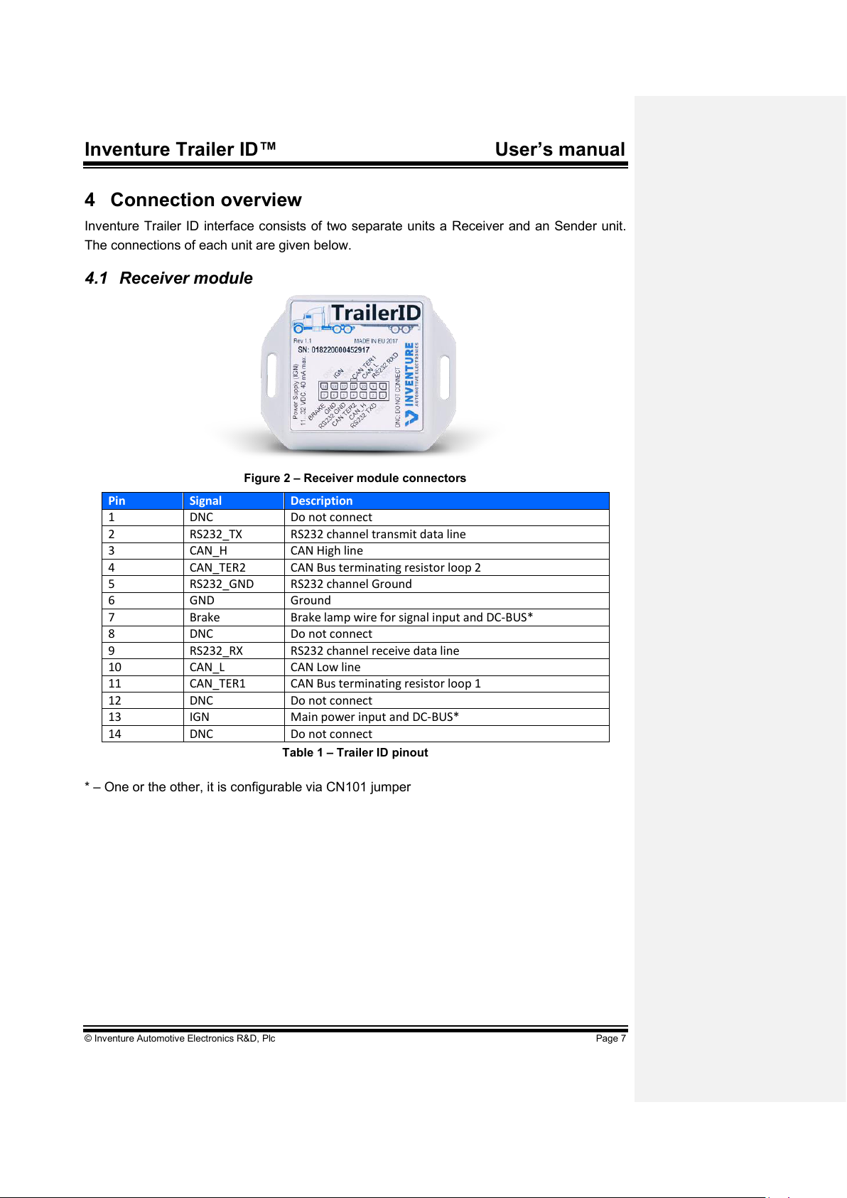
4CONNECTION OVERVIEW................................................................................................ 7
4.1 RECEIVER MODULE ...................................................................................................... 7
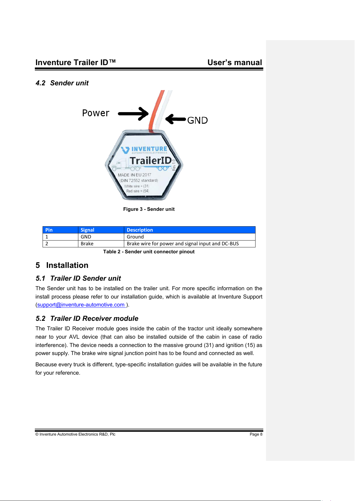
4.2 SENDER UNIT ............................................................................................................... 8
5INSTALLATION .................................................................................................................. 8
5.1 TRAILER ID SENDER UNIT............................................................................................. 8
5.2TRAILER ID RECEIVER MODULE .................................................................................... 8
6OPERATING STATES ........................................................................................................ 9
6.1 DESCRIPTION OF THE STATES....................................................................................... 9
7SYSTEM CHARACTERISTICS ........................................................................................ 10
7.1 RECEIVER MODULE .................................................................................................... 10
7.2 SENDER UNIT ............................................................................................................. 10
8WARRANTY...................................................................................................................... 11
9HOW TO CONTACT INVENTURE?................................................................................. 11

Inventure Trailer ID™ User’s manual
© Inventure Automotive Electronics R&D, Plc Page 4
1 Introduction
Thank you for purchasing an Inventure product. Your new Inventure Trailer ID device is a
carefully engineered, high quality, durable product with modern features. It is designed to
give you the quality and convenience you expect from an automotive measuring instrument.
To familiarize yourself with all the features of your unit, please read the following instructions
carefully. Retain this guide for future reference.
2 Inventure Trailer ID system
2.1 System Overview
Brake lamp wire - 54 (according to DIN 72552)
RS232/HS-CAN
output
Receiver
module
Server
Sender Unit
AVL
1. Figure Main components of the Inventure Trailer ID system
The Inventure Trailer ID system consists of a Trailer Sender unit installed in the rear junction
box of the trailer and a Receiver module which provides RS232 compatible level serial or an
HS-CAN output.
Installation is easy and basically no maintenance is needed since no batteries are installed,
Trailer ID runs on the electricity of the trailer’s brake lamp. When the trailer is coupled to the
tractor and the brake lamp is ignited, the Sender unit transfers the identification number to
the Receiver module as seen on the illustration above.
We designed Trailer ID so that it is compatible with any brand and make and it supports 2
trailer units at the same time. For correct installation please refer to our installation guide and
manuals.
Feldfunktion geändert

Inventure Trailer ID™ User’s manual
© Inventure Automotive Electronics R&D, Plc Page 5
2.2 Main features
With this intelligent interface we provide solution for many different needs. With the Trailer
ID, you can:
Identify, hence track connected trailer units
Replace cumbersome paper-based administration
Early detect inevitable human errors by double-check connected trailers with real-
time data
2.3 Use cases
Among numerous use cases we present a few examples as follows:
Sending real-time alerts on wrong attachments thus avoiding mistaken trips
Sending periodic notifications about upcoming service intervals thus saving you
time and money
Mitigating human error by automatizing the identification procedure
Tracking trailer units through the AVL

Inventure Trailer ID™ User’s manual
© Inventure Automotive Electronics R&D, Plc Page 6
3 Safety notices
Please read the following safety instructions carefully. Inventure Automotive
accepts no liability for damage that results from disregarding the safety
instructions.
Before installation please read this document carefully! Appropriate operation of
the device depends on proper installation.
Usage of the device is permitted for industrial purposes only. It must not be used
in situations in which human lives depend upon the operation of this equipment.
The installation of the device may eventually be in conflict with a country’s
regulations or the vehicle manufacturers (OEM) instructions. The conformance
shall solely be the Customer’s responsibility. Improper device installation may
have an effect on vehicle warranty.
Inventure takes no responsibility for any damages originated in device installation.
Exceeding maximum allowable power supply may impair the device.
Vehicle ignition must be off at the start of installation.
Misuse and/or physical damage on device may lead to loss of warranty.
Fix Inventure Trailer ID device properly to avoid hitting to vehicle elements, or
rattling!
Device should be installed away from direct heat and moisture.
Although device contains (Multi)fuse, application of a 1…3 Amp fuse at power
source is highly recommended.
Inventure Trailer ID device must be installed by professional skilled in automotive
electronics.

Inventure Trailer ID™ User’s manual
© Inventure Automotive Electronics R&D, Plc Page 7
4 Connection overview
Inventure Trailer ID interface consists of two separate units a Receiver and an Sender unit.
The connections of each unit are given below.
4.1 Receiver module
Figure 2 –Receiver module connectors
Pin
Signal
Description
1
DNC
Do not connect
2
RS232_TX
RS232 channel transmit data line
3
CAN_H
CAN High line
4
CAN_TER2
CAN Bus terminating resistor loop 2
5
RS232_GND
RS232 channel Ground
6
GND
Ground
7
Brake
Brake lamp wire for signal input and DC-BUS*
8
DNC
Do not connect
9
RS232_RX
RS232 channel receive data line
10
CAN_L
CAN Low line
11
CAN_TER1
CAN Bus terminating resistor loop 1
12
DNC
Do not connect
13
IGN
Main power input and DC-BUS*
14
DNC
Do not connect
Table 1 –Trailer ID pinout
* –One or the other, it is configurable via CN101 jumper

Inventure Trailer ID™ User’s manual
© Inventure Automotive Electronics R&D, Plc Page 8
4.2 Sender unit
Figure 3 - Sender unit
Pin
Signal
Description
1
GND
Ground
2
Brake
Brake wire for power and signal input and DC-BUS
Table 2 - Sender unit connector pinout
5 Installation
5.1 Trailer ID Sender unit
The Sender unit has to be installed on the trailer unit. For more specific information on the
install process please refer to our installation guide, which is available at Inventure Support
(support@inventure-automotive.com ).
5.2 Trailer ID Receiver module
The Trailer ID Receiver module goes inside the cabin of the tractor unit ideally somewhere
near to your AVL device (that can also be installed outside of the cabin in case of radio
interference). The device needs a connection to the massive ground (31) and ignition (15) as
power supply. The brake wire signal junction point has to be found and connected as well.
Because every truck is different, type-specific installation guides will be available in the future
for your reference.

Inventure Trailer ID™ User’s manual
© Inventure Automotive Electronics R&D, Plc Page 9
6 Operating states
The Inventure Trailer ID has a status LED on its PCB back of the enclosure, which indicates
the current operational mode.
LED Statuses:
Status
Status LED
Normal state
Green
Standby state
Flickering green
DC-BUS active state
Fash flashing red on constant green
No power, or incorrect polarity
No light
6.1 Description of the states
Normal state (green light):
The device is operating normally, it is ready to send or receive messages to the Sender unit.
Standby (flickering green light):
The device goes to this low current consumption mode about 3 seconds after the end of
communication with the Sender unit.
DC-BUS active (fast flashing red on constant green):
Communication is in progress.
No light on LED:
No power supply, or incorrect power polarity.

Inventure Trailer ID™ User’s manual
© Inventure Automotive Electronics R&D, Plc Page 10
7 System Characteristics
7.1 Receiver module
Table 3. Operation and storage characteristics
Other characteristics:
Protected against incorrect polarity
Protected against transient overvoltage
ESD protection up to at least 8 kV (HBM) on any port
7.2 Sender unit
Table 4. Operation and storage characteristics
Other characteristics:
Protected against incorrect polarity
Protected against transient overvoltage
ESD protection up to at least 8 kV (HBM) on any port
Parameter
Symbol
Min.
Typ.
Max.
Unit
Power supply
Voltage supply
VBAT
11
32
V
Operating current
I_op
40
mA
Standby current
I_sb
11
mA
Environmental
characteristics
Storage temperature
T_storage
-40
85
ºC
Operating temperature
T_op
-40
75
ºC
Humidity
RH
5
80
%
Parameter
Symbol
Min.
Typ.
Max.
Unit
Power supply
Voltage supply
VBAT
11
32
V
Operating current
I_op
70
mA
Standby current
I_sb
11
mA
Environmental
characteristics
Storage temperature
T_storage
-40
85
ºC
Operating temperature
T_op
-40
75
ºC
Humidity
RH
5
80
%

Inventure Trailer ID™ User’s manual
© Inventure Automotive Electronics R&D, Plc Page 11
8 Warranty
There is a one-year warranty on the Inventure Trailer ID device from the date of the original
purchase. The warranty covers any defect in materials or workmanship. The warranty is valid
only if the device was operated under normal circumstances in regular use. The warranty
does not include damage from misuse or neglect.
As the Inventure Trailer ID has a well thought design, it is thoroughly tested before release
and it is composed of high quality parts, there should be no need for maintenance of any
parts of the Inventure Trailer ID during normal operation. Should the product damaged or
corrupted, the warranty for the Inventure Trailer ID is no longer valid.
Remember to save your sales receipt in case you ever need warranty service. Please refer
to the serial number of your Inventure Trailer ID in case of any problems. The serial number
can be found on a label outside the box. In case of warranty claims contact your local dealer
or directly Inventure, Inc.
9 How to contact Inventure?
Inventure provides customer support via its World Wide Web (WWW) site. The Inventure
website is available by using from your favorite Internet browser at:
www.inventure-automotive.com
Our website provides a variety of services. Read up-to-date information about the company,
the products, application possibilities and the services. Frequently asked questions and the
corresponding answers are also available on the Inventure site.
If you have problems, questions, suggestions, or you just want to express your opinion about
us or our products, please feel free to write an email to us, and we will surely find a way to
the solution.
support@inventure-automotive.com
Come and visit our website, tell us your experience concerning our product, fill out the
registration form to be able to inform you directly about the latest results of research and
development and the continuously improving customer services.
Your comments are also welcome under the following address:
Inventure Automotive Electronics R&D, Plc.
H-1113 Budapest
11 Tarcali Street
HUNGARY
Phone: +36 1 381-0970

http://www.inventure-automotive.com
Table of contents