Schwarzbeck NSLK 81 Series User manual

RC Option
Datasheet 1/6 Rev. C
0705.140116
NSLK/NNLK 81xx Netznachbildungen mit Option RC für Messempfänger
NSLK/NNLK 81xx LISN with option RC for EMI measurement receivers
Beschreibung: Description:
Mittels der Option RC kann die Netznach-
bildung per Fernsteuerung von einem
geeigneten Messempfänger umgeschaltet
werden. Die Option RC unterstützt die
Codes von Empfängern der Firmen
„Schwarzbeck Mess- Elektronik“ und
„Rohde und Schwarz“ (R&S), Empfänger
der Firma Gauss Instruments nutzen
meist den Schwarzbeck Code. Je nach
Empfängerhersteller wird ein unterschied-
liches Verbindungskabel benötigt, das
zum Lieferumfang gehört. Bitte nennen
Sie uns möglichst bei der Bestellung das
Modell Ihres Empfängers.
The LISN is able to be remote controlled
by an EMI receiver through the option RC.
This option supports codes of receivers
manufactured by Schwarzbeck and Rohde
& Schwarz, receivers manufactured by
Gauss Instruments use Schwarzbeck
code in the most cases. Depending on the
receiver you need a different cable which
is already included within the delivery
content. Please let us know which kind of
receiver you wish to connect to the LISN
when placing your order.
Die 9-polige DSUB Buchse befindet sich
auf der Rückwand der Netznachbildung.
Deren Pinbelegung ist Tabelle 1 zu ent-
nehmen. Wichtig: Vor der Inbetriebnah-
me muss unbedingt die Steckerbelegung
geprüft werden, um mögliche Beschädi-
gungen an angeschlossenen Geräten zu
vermeiden. Die mit TTL bezeichneten
Signale sind bei + 5V aktiv. Die Ansteue-
rung muss mit statischen Logiksignalen
erfolgen. Die Einstellung bleibt nur so
lange erhalten, wie die Logiksignale anlie-
gen. Die Spalte „DSUB25 R&S EMI Re-
ceiver“ bezieht sich auf die Pin-Belegung
von R&S Empfängern, die einen 25 poli-
gen Userport aufweisen (ohne Gewähr,
technische Änderungen vorbehalten).
The 9 pin DSUB socket is located at the
LISN's rear panel. The pin assignment is
given in table 1. It is very important to
verify the correct assignment to avoid
damage of connected components! The
signals marked "TTL" are active high
(+ 5V). The control signals have to be
present permanently. The chosen state of
the LISN is only present as long as logic
signals are present. The column “DSUB25
R&S EMI Receiver” refers to R&S receiv-
ers providing a 25pin userport (without
guarantee, technical matters might
change).
Hinweis: Da zur Ansteuerung quasi stati-
sche Signale verwendet werden, sind
keinerlei Störspektren zu erwarten. Eine
Filterung der Ansteuersignale selbst ist
nicht erforderlich. Bei Kabinendurchfüh-
rungen genügt in der Regel eine sorgfälti-
ge Masseverbindung des Schirms.
Note: Since the remote control signals are
quasi steady state, no disturbance spectra
are caused by these signals. An additional
filtering of the remote control signals itself
is not required. Reliable shield connec-
tions at feed through - junctions are usual-
ly sufficient.
Je nach angeschlossenem Empfänger
werden unterschiedliche Signale ausge-
wertet. Wenn an Pin 1 (Remote) des
DSUB Verbinders eine Spannung von
>2.4 V bis 5 V anliegt, wird der Schwarz-
beck Modus aktiviert und die LISN geht in
den Remotebetrieb. In diesem Fall sind
die Schalter auf der Frontplatte der LISN
außer Funktion. Wird die Spannung an
Pin 1 des DSUB Verbinders abgeschaltet,
wechselt die LISN wieder in den Lokalbe-
trieb.
Depending on the connected receiver
different signals are used to control the
LISN. As long as there is a voltage > 2.4 V
<= 5 V present on pin 1 the mode for
Schwarzbeck receivers is active and the
LISN is in remote mode. In this case the
switches on the front panel are inactive.
As soon as the voltage on pin 1 is
switched off the LISN activates the local
mode and the switch on the front panel is
working again.

RC Option
Datasheet 2/6 Rev. C
0705.140116
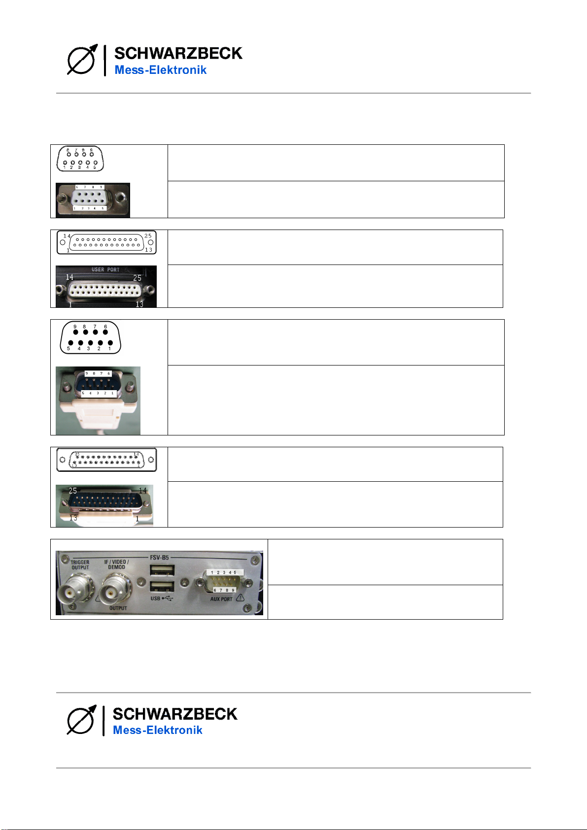
Liegen an Pin 8 des DSUB Steckverbin-
ders etwa +5 V an, schaltet die Logik in
den R&S Modus. Dies ist bereits im mit-
gelieferten Kabel für Sie geschehen, d.h.
sobald das Kabel, das mit R&S markiert
ist, an LISN und Empfänger angeschlos-
sen wird, liegen die 5 V bereits an. Sobald
eine der Steuerleitungen des Userports
aktiviert wird (0 V, low aktiv!) wechselt die
Logik von Local auf Remotebetrieb.
Applying a voltage of approx. 5 VDC to
pin 8 of the DSUB connector causes the
LISN to switch to Rohde & Schwarz mode.
This will automatically happen as soon as
you connect the cable marked with R&S to
the LISN and to the receiver since pin 8 is
connected to +5 VDC within the connect-
or. As soon as one of the control wires
applies a 0 V level to the LISN the logic
switches from local into remote mode.
Durch LEDs werden der jeweils erkannte
Modus und der aktivierte Messkanal an-
gezeigt.
LEDs indicate which mode is currently
active and which channel is measured.
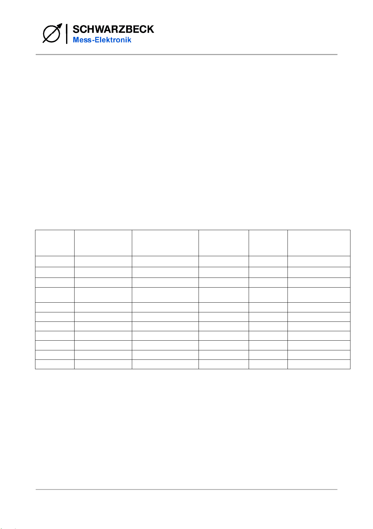
Hinweis: Messempfänger der Firma
Schwarzbeck liefern ein kodiertes Signal
in positiver Logik. In der Tabelle 2 sind die
dazugehörenden Signalkombinationen
aufgelistet.
Notice: EMI receivers manufactured by
Schwarzbeck supply a coded signal using
positive logic. You can see the assign-
ments of code and active port in table 2.
R&S Messempfänger hingegen geben
ihre Steuerinformation Low-Aktiv aus (0V
aktiviert den gewünschten Messpfad).
EMI receivers manufactured by Rohde &
Schwarz supply their information uncoded
using negative logic (0V sets the active
path).
WICHTIG!
Die LISN benötigt für die Relais und die
LEDs eine Stromversorgung, auch im
Lokalbetrieb! Diese erfolgt wahlweise
über die eingebaute Kaltgerätebuchse auf
der Rückseite der LISN oder über den
Messempfänger. Der Strombedarf liegt
bei maximal 50 mA. Soll die Netznachbil-
dung über den Messempfänger versorgt
werden, so wird ein Potential von +12 V
an Pin 9 der DSUB Buchse benötigt, wel-
ches sowohl von Schwarzbeck als auch
von älteren Rohde & Schwarz Empfän-
gern üblicherweise automatisch zur Ver-
fügung gestellt wird.
IMPORTANT!
A power supply is needed for the LEDs
and the relays even when you want to
use the local mode! You can either con-
nect a power cord to the connector on the
backside of the LISN or you can power the
LISN using the EMI receiver on pin 9 of
the DSUB connector. The current con-
sumption is lower than 50 mA. If the LISN
is supposed to be supplied utilizing the
EMI receiver, a voltage of +12 VDC has to
be connected to pin 9 of the DSUB con-
nector which is usually provided by
Schwarzbeck as well as by former Rohde
& Schwarz receivers automatically.
ACHTUNG! Der ESL und der ESR von
Rohde & Schwarz sowie die Empfänger
der Firma Gauss Instruments stellen keine
ausreichende Energieversorgung (nur 5 V
statt 12 V!) mehr zur Verfügung! Bei Ver-
wendung dieser Messempfänger muss
unbedingt das Kaltgerätekabel ver-
wendet werden, um die Umschalteinheit
der Netznachbildung mit Energie zu ver-
sorgen!
ATTENTION! The ESR as well as the
ESL EMI receiver made by Rohde &
Schwarz and the receivers made by
Gauss Instruments do not provide a suffi-
cient power supply anymore (only 5 V
instead of 12 V!). If you plan to use one of
these devices you have to plug in the
IEC power cord to the LISN to provide
the switching unit with energy by all
means!
Fehlt die Spannungsversorgung für die
RC-Option, so wird die Netznachbildung
automatisch in die sog. Sicherheitspositi-
on geschaltet, d.h. alle Pfade werden mit
50 Ωabgeschlossen und an die BNC
Buchse wird KEIN Signal ausgekoppelt.
If the power supply for the RC-option is
missing, the LISN will switch to the so
called safety position automatically. That
means that all paths will be terminated
with 50 Ωand NO signal will be coupled to
the BNC connector.

RC Option
Datasheet 3/6 Rev. C
0705.140116
Der eventuell angeschlossene Prüfling
funktioniert dennoch, sobald er von der
Netznachbildung gespeist wird, es ist aber
keine Messung möglich. Kontrollieren Sie
bitte vor der Messung, dass die entspre-
chenden LEDs an der Frontseite leuchten.
The possibly connected EUT will still work
as long as it is supplied with power from
the LISN but no measurement will be per-
formed. Please check that the correct
LEDs at the front panel are illuminated
before the measurement.
Bei Verwendung der Kabel RCCAB3,
RCCAB4 oder RCCAB6 muss zwingend
der IEC Kaltgerätestecker auf der Rück-
seite der Netznachbildung zur Stromver-
sorgung genutzt werden.
If the cables RCCAB3, RCCAB4 or
RCCAB6 are being used the IEC power
connector at the back panel of the LISN
has to be used to provide sufficient power
to the LISN.
Wird das Kabel RCCAB4 verwendet,
schaltet die Netznachbildung sofort in den
Fernsteuermodus sobald sie mit dem
Messempfänger verbunden wird. Um den
Pfad manuell zu messen, muss die Ver-
bindung wieder getrennt werden.
If the cable RCCAB4 is being used the
LISN switched to remote mode as soon as
it gets connected to the EMI receiver. To
be able to use manual mode the cable has
to be disconnected again.
Tabelle 1: Steckerbelegung
Table 1: pin assignment
LISN Schwarzbeck EMI
receiver R&S Userport/
Agilent MXE AUX/IO R&S Userport
ESIB R&S AUX
port
Gauss Instruments
Userport
RCCAB1 RCCAB2 RCCAB6 RCCAB3 RCCAB4
DSUB9 fem.
DSUB9 fem.
DSUB25 fem.
DSUB25 fem. DSUB9 male
DSUB25 fem.
1 1 Remote (+5V) - - - 13 Remote (+5V)
2 2 D, TTL 18 Port 5 /PE 18 Port 5 /PE 3150 kHz high
pass filter 17 D, TTL
3 3 C, TTL 16 Port 3 /L2 16 Port 3 /L2 7Phase L2 16 C, TTL
4 4 B, TTL 15 Port 2 /L1 15 Port 2 /L1 6Phase L1 15 B, TTL
5 5 A, TTL 14 Port 1 /N 14 Port 1 /N 2Phase N 14 A, TTL
6 6 GND 12 GND 12 GND 8GND 12 GND
7 7 - 17 Port 4 /L3 17 Port 4 /L3 4Phase L3 -
8 8 - 25 +12V (remote R&S) 24 +5V (remote R&S)
1+5V -
9 9 +12V 25 +12V -- -
Abhängig vom verwendeten Messempfänger und von der installierten Firmware-Version kann es sein, dass
sich die Schutzleiterdrossel nicht direkt vom Empfänger aus fernsteuern lässt.
Depending on the EMI receiver being used and the firmware version installed it could possibly be that you
won’t be able to remote control the PE choke directly at the EMI receiver.

RC Option
Datasheet 4/6 Rev. C
0705.140116
Tabelle 2: Kodierung des Remotesignals für Schwarzbeck Messempfänger
Table 2: code of the remote signal for Schwarzbeck EMI receivers.
D C B A Funktion/function
0 0 0 0
Keine Phase/
no phase
Ohne Schutzleiterdrossel/
direct connection to ground
0 0 0 1
Keine Phase/
no phase
Ohne Schutzleiterdrossel/
direct connection to ground
0 0 1 0
Phase 0
Ohne Schutzleiterdrossel/
direct connection to ground
0 0 1 1
Phase 1
Ohne Schutzleiterdrossel/
direct connection to ground
0 1 0 0
Phase 2
Ohne Schutzleiterdrossel/
direct connection to ground
0 1 0 1
Phase 3
Ohne Schutzleiterdrossel/
direct connection to ground
0 1 1 0
Keine Phase/
no phase
Ohne Schutzleiterdrossel/
direct connection to ground
0 1 1 1
Keine Phase/
no phase
Ohne Schutzleiterdrossel/
direct connection to ground
1 0 0 0
Keine Phase/
no phase
Mit Schutzleiterdrossel/
with ground choke
1 0 0 1 Keine Phase/
no phase
Mit Schutzleiterdrossel/
with ground choke
1 0 1 0 Phase 0
Mit Schutzleiterdrossel/
with ground choke
1 0 1 1 Phase 1
Mit Schutzleiterdrossel/
with ground choke
1 1 0 0 Phase 2
Mit Schutzleiterdrossel/
with ground choke
1 1 0 1 Phase 3
Mit Schutzleiterdrossel/
with ground choke
1 1 1 0 Keine Phase/
no phase
Mit Schutzleiterdrossel/
with ground choke
1 1 1 1 Keine Phase/
no phase
Mit Schutzleiterdrossel/
with ground choke

RC Option
Datasheet 5/6 Rev. C
0705.140116
Tabelle 3: Bestellnummer des passenden Fernsteuerkabels
Table 3: Order number of the suitable remote control cable
Kabeltyp/
type of cable Passend für/
suitable for
RCCAB1 Schwarzbeck Messempfänger/
Schwarzbeck EMI receiver
•FMLK 1518
•FCKL 1528
•FCLE 1535
RCCAB2 Rohde & Schwarz Messempfänger
mit 25pol. Userport.
Rohde & Schwarz EMI receiver
equipped with a 25 pin userport:
•ESPI
•ESCS
•ESCI
•ESU
•ESHS30
Agilent MXE Messempfänger mit
25pol. AUX/IO.
Agilent MXE receiver with a 25 pin
AUX/IO port
RCCAB3 Rohde & Schwarz Messempfänger
mit 9 pol. AUX Port/
Rohde & Schwarz EMI receiver
equipped with a 9 pin AUX port:
•ESL (nur mit Option/ with
option R&S FSL–B5 only)
•ESR
•ESRP
RCCAB4 Gauss Instruments TDEMI mit 25pol.
Userport
Gauss Instruments TDEMI equipped
with a 25pin userport
RCCAB5 PMM 9010 mit DSUB15 Buchse
PMM 9010 with DSUB15 jack
RCCAB6 Rohde & Schwarz ESIB
Tabelle 4: Auswahl der LISN in Empfängermenüs
Table 4: Selection of LISN in the receiver software
Verwendete Netznachbildung
LISN in use Auswahl des äquivalenten LISN Modells in der R&S
Software EMC32 oder im Menü des Empfängers
Select the following LISN type in the R&S EMC32 soft-
ware or in the menu of the receiver
NSLK 8127 ESH3-Z5
(ENV216 – eingeschränkte Funktionalität)
(ENV216 - limited functionality)
NSLK 8126
NSLK 8128
NNLK 8121
NNLK 8129
NNLK 8130
ESH2-Z5
(ENV4200 - eingeschränkte Funktionalität)
(ENV4200 - limited functionality)

RC Option
SCHWARZBECK MESS – ELEKTRONIK OHG
An der Klinge 29
69250 Schönau, Germany
Phone: +49 6228 1001
Fax.: +49 6228 1003
E-Mail: office@schwarzbeck.de
www.schwarzbeck.de
Datasheet 6/6 Rev. C
0705.140116
Übersicht der Steckverbinder für die Option RC
overview of the connectors used for option RC
Belegung DSUB9 Buchse an der Rückwand der LISN/ Schwarzbeck Emp-
fänger, Sicht auf die Kontaktseite (nicht die Lötseite!)
Pin assignment DSUB9 jack (“female”) located at the rear panel of the
LISN/ Schwarzbeck EMI receiver (face view, NOT the soldering side!)
Belegung DSUB25 Buchse an der Rückwand eines R&S Empfängers,
Sicht auf die Kontaktseite (nicht die Lötseite!)
Pin assignment DSUB25 jack (“female”) located at the rear panel of a R&S
EMI receiver (face view, NOT the soldering side!)
Belegung DSUB9 Stecker für Schwarzbeck Empfänger, Sicht auf die Kon-
taktseite (nicht die Lötseite!)
Pin assignment DSUB9 plug (“male”) for Schwarzbeck EMI receiver (face
view, NOT the soldering side!)
Belegung DSUB25 Stecker für R&S Empfänger, Sicht auf die Kontaktseite
(nicht die Lötseite!)
Pin assignment DSUB25 plug (“male”) for R&S EMI receiver (face view,
NOT the soldering side!)
Rohde & Schwarz Option FSL–B5 mit der AUX
Schnittstelle. Nur wenn diese Option zum ESL hin-
zubestellt wird, lassen sich Netznachbildungen
fernsteuern.
Rohde & Schwarz option FSL–B5 featuring the
AUX port. Only with this option added the ESL is
able to remote control a LISN.
This manual suits for next models
1
Other Schwarzbeck Receiver manuals