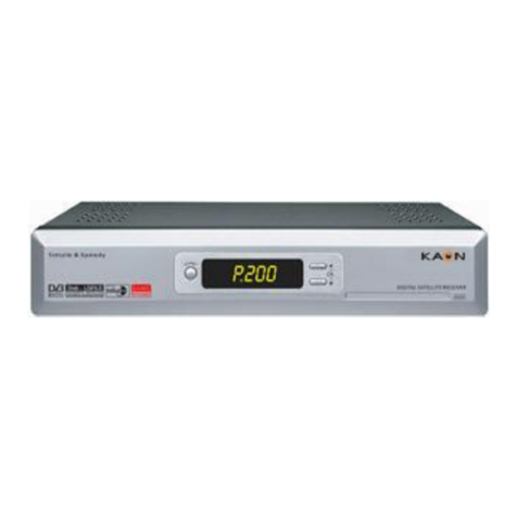
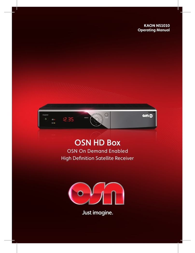
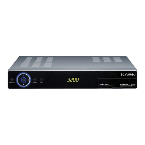
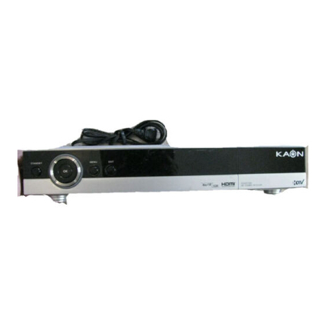
Kaon KTSC-570 User manual

COVER_ENG
Digital Combo Receiver
KTSC-570
User's Manual

2
DIGITAL COMBO RECEIVER
General Safety
Warning
Always follow these instructions to avoid the risk of injury to
yourself or damage to your equipment.
Unplug the receiver from the AC power outlet before cleaning.
Use only a damp cloth for cleaning the exterior of the receiver.
Do not use accessories or attachments not recommended by the receiver manufacturer
as they may cause problems to the equipment and will void the warranty.
Do not place the receiver on an unstable cart, stand, tripod, bracket, or table.
The receiver may fall, causing serious personal injury and damage to the receiver.
Do not block or cover the slot opening in the receiver.
These are provided for ventilation and protection from overheating.
Never place the receiver near or over a radiator or any heat source.
Do not place the receiver in an enclosure such as a cabinet without proper ventilation
Do not stack the receiver on top of or below other electronic devices.
The apparatus shall not be exposed to dripping or splashing and with no object filled with liquids,
such as vases, shall be placed on the apparatus.
Operate the receiver using only the type of power source indicated on the marking label.
Unplug the receiver power cord by gripping the power plug, not the cord.
Route power supply cord so that are not likely to be walked on or pinched by items
placed upon or against them. Pay particular attention to the cords that plugs in the convenience receptacles,
and the point where they exit from the unit.
Use an outlet that contains surge suppression or ground fault protection.
For added protection during a lightning storm, or when the receiver is left unattached
and unused for long periods of time, unplug it from the wall outlet and disconnect
the lines between the receiver and the antenna. This will provide some protection
against electrical damage caused by lightning or power line surges.
Servicing
Do not attempt to service the receiver yourself, as opening or
removing covers may expose you to dangerous voltage,
and will void warranty.
Refer all servicing to authorized service personnel.
3
DIGITAL COMBO RECEIVER
General Safety
Digital Combo Receiver
Owner's Manual
OPERATION HANDBOOK
Before operation,
Please read the entire manual thoroughly
and retain it for future reference.
Channel Search
Edit Channel List
System Setting
Program Guide
Channel List
Common Interface (Option)
Utility (Option)

4
DIGITAL COMBO RECEIVER
Contents
Remote Control Unit..........................................................6
Front Panel ....................................................................8
Rear Panel .....................................................................10
Connecting Your Equipment ..................................................11
Basic Operation ...............................................................14
Menu Guide ...................................................................18
EasyInstallation..................................................................18
MainMenu.....................................................................20
ChannelSearch..................................................................21
DiSEqC:None,Switch..........................................................21
DiSEqC:Motor................................................................24
DiSEqC:USALS...............................................................27
TerrestrialSearch...............................................................30
ChannelList.....................................................................32
EditChannelList.................................................................33
Program Guide. . . . . . . . . . . . . . . . . . . . . . . . . . . . . . . . . . . . . . . . . . . . . . . . . . . . . . . . . . . . . . . . . . . 36
SystemSetting ..................................................................37
MenuLanguage ...............................................................37
AudioLanguage................................................................37
SubtitleLanguage..............................................................38
SCARTOutput.................................................................38
ScreenType.......................................................................38
BannerTime ......................................................................39
RFMode .........................................................................39
RFChannel .......................................................................39

5
DIGITAL COMBO RECEIVER
Contents
LocalTime........................................................................40
MenuTransparency ................................................................40
ChangePINCode..................................................................40
ParentalLock......................................................................41
ReceiverLock .....................................................................41
MenuLock........................................................................41
S/PDIFOutput(Option)..............................................................41
AutoPower.......................................................................42
FactoryReset......................................................................42
SystemInformation.................................................................42
Common Interface (Option).........................................................43
Utility (Option).......................................................................44
Troubleshooting...............................................................46
Technical Specifications. . . . . . . . . . . . . . . . . . . . . . . . . . . . . . . . . . . . . . . . . . . . . . . . . . . . . . . 48
Menu Map.....................................................................49

6
DIGITAL COMBO RECEIVER
Remote Control Unit
Note! 1 : When inserting batteries, make sure that the polarity (+/-) is correct.
Note! 2 : The design of the Remote Control Unit may be changed without any notice in advance.
STAND BY
"
NUMERIC BUTTON
#
TV/STB
$
CH UP/DOWN
&
MUTE
(
LEFT/RIGHT
*
EXIT
,
GREEN BUTTON
/
SUBTITLE(RED BUTTON)
0
P.STD
3
RECALL
7
P.SIZE
4
EPG
8
%
TV/RADIO
'
VOL UP/DOWN
)
PAUSE
+
UP/DOWN
-
OK
.
MENU
1
YELLOW BUTTON / TIMER
2
INFO(BLUE BUTTON)
6
TEXT
9
SLEEP
5
A.L/R
:
A.LANG

7
DIGITAL COMBO RECEIVER
Remote Control Unit
"
STAND BY To switch between operation and stand by mode.
#
NUMERIC BUTTONS To select the channel and enter the channel edit and PIN code.
$
TV/STB To switch between TV and STB receive mode.
%
TV/RADIO To switch between TV and Radio.
&
CHANNEL UP/DOWN To change channel up and down.
'
VOLUME UP/DOWN To increase or decrease the volume.
(
MUTE To enable or disable audio.
)
PAUSE To pause or play video.
*
LEFT/RIGHT To move left or right on the menu.
To increase or decrease the volume.
+
UP/DOWN To move up or down on the menu.
,
EXIT To return the normal viewing mode from a menu.
-
OK To confirm your choice.
.
MENU To display the Main Menu on the screen or return to the previous menu.
/
GREEN To see the current information banner guide or the satellite list.
0
SUBTITLE(RED) To enable or disable subtitle or change the channel list mode.
1
YELLOW To sort channel list.
2
INFO(BLUE) To display the information box on the screen.
3
P.STD To change picture standard. (Option)
4
P.SIZE To change screen size.
5
A.L/R To select the sound mode.(Mono, Left, Right, Stereo)
To display the reserved list. (Option)
6
TEXT To see the teletext by OSD. (Option)
7
RECALL To return to the previous channel.
8
EPG To display the TV/RADIO program guide.
9
SLEEP To select a present time interval for automatic shut off.
:
A/LANG To select the audio language.

8
DIGITAL COMBO RECEIVER
Note! : The design of the Front Panel may be changed without any notice in advance.
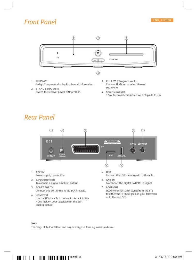
Front Panel
1. POWER Switch the receiver power "ON" or "OFF".
2. CH
p
or
q
( Program
p
or
q
) Channel Up/Down or select item of sub-menu.
3. VOL - / + ( Program t/u)Volume Up/Down or select item of sub-menu.
4. OK Select a program, a highlighted line or parameter value.
5. EXIT Exit from parameter and cancel selected function.
6. MENU To see main menu.
7. SEG. DISP. 4-digit 7-segment display channel information.
8. CAM Slots (Depending on model)
2 Slots for Common Interface CAM (VIACCESS, IRDETO,
NAGRAVISION, CRYPTOWORKS, CONAX) with SmartCard.

9
DIGITAL COMBO RECEIVER
KEY & DISPLAY The message of the 7-segment LED (Light-Emitting Diode) on the STB
and keys are explained as below.
Standby Mode
Current Program Number on TV List
System Booting Current Program Number on Radio List
Power Off
TV Mode
MICOM Version
STB Mode
Upgrade
Boot Loader Version
Upgrade Procedure
Download
Upgrade Complete
Down Load Procedure
Front Panel Display Message
Caution
Please do not plug in the main power supply cord until you have finished all of
the connections!
If you want to enjoy watching scrambled broadcasting channels, you need
to purchase the CAMs and smart cards from a service provider’s sales
department.
However, broadcasting channels from multiple service providers call for
multiple CAMs and Smart cards.
Receivers which have only the CAMs and smartcards provided by the one
service provider can show several broadcasting channels of the provider.
Please refer to manuals provided by service providers for details because the
CAM and smartcards are featured with unique menus, apart from menus
given by the receiver.
Watching "Free-To-Air" channel is available regardless of the CAM and
smart cards.
As service providers download new information to smart cards if necessary,
those who have CAMs and smart cards should always put the smart cards
in proper slots.
CAM(Conditional Access Module) and Smart Card(CI and CAS embeded model only)
Front Panel

10
DIGITAL COMBO RECEIVER
Rear Panel
Note! : The design of the Rear Panel may be changed without any notice in advance.
1. POWER SUPPLY 90 ~ 250V AC, 50/60Hz.
2. S/PDIF Output for connection to a digital amplifier.
3. SCART FOR VCR Connect this port to the VCR via SCART cable.
4. SCART FOR TV Connect this port to the TV via SCART cable.
5. VIDEO Video connection port to the TV or other equipment.
6. AUDIO Audio connection port to the TV or other equipment.
7. N/C No Connection.
8. RF LOOP IN To connect to a general aerial antenna and cable jacks to a RF
input jack on the STB.
9. TV OUT To connect a TV via a coaxial cable.
10. RS-232 To connect to a personal computer for software upgrade.
11. LNB To connect to a satellite antenna and cable jacks.
12. LOOP THROUGH Used to connect a RF signal from the STB to either the RF
input jack on your television or to the STB.
13. ANTENNA To connect to a digital terrestrial antenna input.
14. RF LOOP OUT Used to connect a RF signal from the Receiver to either the RF
input jack on your television or to the Receiver (RF Loop In).

11
DIGITAL COMBO RECEIVER
There are several ways of connecting the STB to your TV, VCR and/or Hi-Fi SYSTEM. Consult your local
supplier for assistance in setting-up your system that is best suited to your requirements.
How to connect your STB to various systems
1. Connect STB to a TV set
Connect your STB to a TV set with SCART, if your TV set is equipped for it.
Alternatively you can use A/V, TV out (UHF) or S/Video jacks.
2. Connect STB to a Hi-Fi System
Connect a RCA stereo cable from the AUDIO L/R jacks, S/PDIF on your STB to the LINE,
AUX, SPARE or EXTRA input jacks on your Hi-Fi System.
3. Connect STB to a Digital Audio System
If you have a DAC with S/PDIF coaxial cable input, you can connect the STB with it to enjoy
higher quality sound. Connect S/PDIF coaxial cable to a digital amplifier.
4. Loop Through
If you have another analogue or digital STB and you wish to use the same CATV line then you can
connect it via the loop through. Connect one end of the coaxial cable to the Loop Through on the STB
and connect the other end to the CATV ANT. IN jackon your second STB.
Connecting Your Equipment
Note! 1 : The design of the Rear Panel may be
changed without any notice in advance.
Note! 2 : Connect the cable with input jack on STB
properly shown in the picture.

12
DIGITAL COMBO RECEIVER
Connecting Your Equipment
TV with Trerrestrial Antenna
1. Connect one end of RCA/Cinch cable to the RCA/
Cinch jack on the back of the STB and the other
end to a RCA/Cinch jack on your TV. If your TV
doesn’t have a RCA/Cinch jack, connect one end
of RF cable to the TV OUT on the back of the
STB and the other end to a RF input jack on your TV.
2. Connect one end of RF cable to the ANT IN on
the back of the STB and the other end to a
terrestrial antenna connection or the jack for
the public antenna on the wall.
3. Finally connect the coaxial cable from the LNB to the
LNB IN jack on back of the STB.
(To RCA/Cinch on your TV)
(If your TV doesn't have
RCA/Cinch jack)
Note! 1 : The design of the Rear Panel may be
changed without any notice in advance.
Note! 2 : Connect the cable with input jack on STB
properly shown in the picture.
TV with Motorized System (DiSEqC 1.2)
1. Connect one end of RCA/Cinch cable to the
RCA/Cinch jack on the back of the STB and the
other end to a RCA/Cinch jack on your TV.
If your TV doesn’t have a RCA/Cinch jack, connect
one end of RF cable to the TV OUT on the back of
the STB and the other end to a RF input jack on
your TV.
2. Connect one end of your coaxial cable tothe LNB IN
connector on the STB and the other end to the REC
or Receiver connector on the DiSEqC 1.2 motor.
3. Connect the coaxial cable from the LNB to the LNB
connector on the DiSEqC 1.2 motor.
(To RCA/Cinch on your TV)
(If your TV doesn't have
RCA/Cinch jack)
Note! 1 : The design of the Rear Panel may be
changed without any notice in advance.
Note! 2 : Connect the cable with input jack on STB
properly shown in the picture.

13
DIGITAL COMBO RECEIVER
Connecting Your Equipment
Reference
1. DiSEqC 1.0 Connection
All our receivers are designed to be DiSEqC 1.0 and DiSEqC 1.2 compatible.
This allows multiple antennas to be connected to the STB at the same time.
If you have two or more fixed antennas or LNBs then we recommend you use a DiSEqC 1.0 switch.
Connect the coaxial cable from the first LNB to the LNB 1 or LNB A input connector of the DiSEqC
switch.
Do the same for any other LNBs that you have.
Connect one end of a coaxial cable to the RF output connector of the DiSEqC switch,
connect the other end to the LNB IN socket on the STB.
2. DiSEqC 1.2/ USALS Connection
To the digital receiver, you can connect either a single satellite antenna directly or LNB of multi-feed
equipment.
When installing the USALS please consult and receive assistance from an installation specialist,
or ensure that the 0-degree angle of the motor is facing due south when installing, for proper
operation.

14
DIGITAL COMBO RECEIVER
Basic Operation
1. Program Information
After the television channels have been programmed, you will see the
information box each time you change the channels.
1. Every time you change channels you will receive program information for a
few seconds. (In the "Banner Time" menu you can select how long this
information will be shown.)
2. You may change channel lists with the
por qbuttons
.
You can get "Channel Banner" on the bottom of the screen.
3. When you press the COLOR button, you can use banner as a simple
channel operation. In this case, you can get a simple EPG on right view.
2. Now-Information Banner
1. During "Channel Banner" is appearing, when you press GREEN
button, you can get "Now-Information Banner".
2. Using "Now-Information Banner", you can get a simple EPG of
"Now-Information".
3. Next-Information Banner
1. During "Channel Banner" is appearing, when you press YELLOW button,
you can get "Next-Information Banner"
2. Using "Next-Information Banner", you can get a simple EPG of
"Next-Information".
Basic Function

15
DIGITAL COMBO RECEIVER
Basic Operation
4. Channel-Information Banner
1. During "Channel Banner" is appearing, when you press INFO(BLUE)
button, you can get "Channel-Information Banner".
2. Using "Channel-Information Banner", you can get a detailed channel
listing information.
5. Volume Control/Mute
1. To control audio volume, press VOL
por qbuttons
.
2. Volume control bar will be appeared in bottom of the TV screen
3. After time-out in 1 second, volume control bar will disappear.
To temporarily stop the volume, press the MUTE button.
To cancel mute, press the MUTE button again or press the VOL
por q
buttons
.
6. Teletext / Subtitle
1. Press the RED button, popup window will be displayed on the screen.
2. Select the off, then subtitle function is off.
3. Select the Subtitle, then you can see the subtitle language.
4. Select the Teletext, then you can see the teletext language.
Basic Function

16
DIGITAL COMBO RECEIVER
Basic Operation
7. Timer
The user can reserve a desired program at a desired time by using
the Timer function.
1. Once, Daily, Weekly Reservation.
♦Use the
p, q, t, or ubuttons
in the Timer Setting screen to select
the date and time.
♦Press the OK button to save the selected time on the Disk icon.
The program will record at each and every selected time.
Once : once
Daily : daily
Weekly : weekly
Off : off
2. Reservation from EPG (Option).
♦Selects the desired program to be reserved from the EPG screen.
Pressing the YELLOW button will open the Timer Window.
8. Simple Channel List
1. When you press OK button during receiving service stream,
you can get "Channel List" view.
2. Using
por qbuttons
in "Channel List" view, you can choose
another channel.
3. After moving highlight on a channel, then press OK button.
4. Press SUB-T(RED) button to change channel listing.
5. To get the channel sort list, press the YELLOW button.
Pop up window will be displayed on the screen.
When you press YELLOW button, the sort and CAS sort are toggled.
6. Select the sort list you want with
por qbuttons
and then
press OK button to get it.
Basic Function

17
DIGITAL COMBO RECEIVER
Basic Operation
9. Soundtrack
1. When you want to change the Audio Language of current channel,
press the A.LANG button on the remote control.
The on-screen menu is displayed on the left side of the screen.
2. Use
por qbuttons
to choose the audio you want.
3. To cancel or exit, press the A.LANG button again.
You can change a default audio language in the system setting menu mode.
10. To change the audio output
1. Press the A.L/R button on the remote control unit to change
the output.
2. Then on-screen menu is displayed on the top right side of the screen.
3. Press the A.L/R button repeatedly to change the sound mode.
(Mono, Left, Right, Stereo)
Basic Function

18
DIGITAL COMBO RECEIVER
Menu Guide
Before you can view the television or radio program, you must perform the
installation procedure first.
Therefore you will see only "Easy Installation Menu" at first when you plug in
your system.
The Easy Installation gives you the convenience of selecting various languages,
adjusting the time and channel search.
1. Automatic Installation by "Easy Installation"
The Installation Wizard is user friendly to assure easy set-up of
the receiver by the new user.
2. System Connection
Connect STB to all peripheral devices such as TV, Audio, Video etc..
3. Power On
Turn on the STB power and other devices.
4. Power Off
When you press the STAND BY button again.
The STB will display "OFF".
Easy Installation

19
DIGITAL COMBO RECEIVER
Menu Guide
Language
The first option is "Language Select" to select the desired language of
the Menu, Audio, or Subtitle.
Place the cursor on the sub menu by pressing the keys and press
the OK button to change language.
The Language of Menu, Audio, or Subtitle will be changed to the selected
language.
Local Time
You can set your local time according to your location.
To set the local time, press NUMERIC buttons.
Channel Search
You can search the channels according to the DiSEqC mode.
Press the OK button. Channel Search screen will appear.
Easy Installation

20
DIGITAL COMBO RECEIVER
Menu Guide
Press the MENU button on the remote control unit.
You will see the "Main Menu" on the screen.
1. You can move into the desired submenu using
por qbuttons
.
2. You should enter the PIN code in order to move into the corresponding
submenu in case of "Edit Channel List" or "System Setting".
3. Press OK button to confirm your selection.
4. Press the MENU button to return to previous menu.
Or press the EXIT button to quit the Menu system completely.
Main Menu shows the following information.
Channel Search : Satellite(None/Switch, Motor, USALS), Terrestiral
Channel List : Shows Favorite 1~8 all channels, sort, CAS sort.
Satellite sort.
Edit Channel List : Edits favorite 1 ~ 8, Lock, Skip, Delete, Move,
or Genre.
Program Guide : Shows Now, Next, Weekly program guide.
System Setting : Set Menu Language, Audio Language,
Subtitle Language, SCART Output, Screen Type,
Banner Time, RF Mode, RF Channel, Local Time,
Menu Transparency, Change PIN code,
Parental Lock, Receiver Lock, Menu Lock,
SPDIF Output, Auto Power, Factory Reset,
and System Information.
Common Interface : Shows scramebled channels by using common
interface modules.
Utility (option) :Game, Demonstration, Calendar, Zoom, Calculator.
Main Menu
Table of contents
Other Kaon Receiver manuals

Kaon
Kaon KVR-1000 User manual

Kaon
Kaon KCF-220 MCO User manual

Kaon
Kaon KTF-I2001CO User manual

Kaon
Kaon KTSC-S660HD User manual

Kaon
Kaon KCF-200CO User manual

Kaon
Kaon 700 User manual

Kaon
Kaon NS1010 User manual

Kaon
Kaon KSC-570 User manual

Kaon
Kaon KSF-A3200HR User manual

Kaon
Kaon KSTB2100 Troubleshooting guide