2 | Fieldbus Guide | Version 1.02 www.invertekdrives.com
1. About This Document
......................
4
1.1. Compatibility
..................................
4
1.2. Intended Audience
............................
4
1.3. Additional Documentation
......................
4
2. Fieldbus Connectivity
......................
5
2.1. Overview
.....................................
5
3. Parameter Configuration for Fieldbus
Operation
..................................
6
3.1. Overview
.....................................
6
4. Modbus RTU
..............................
8
4.1. Overview
.....................................
8
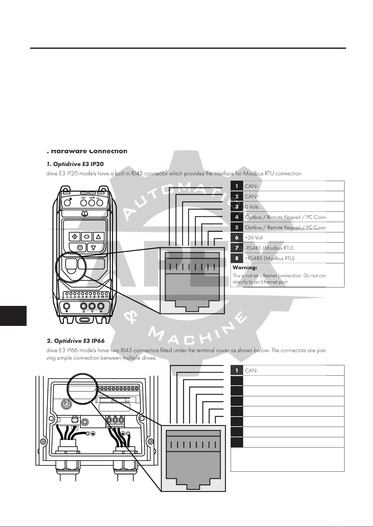
4.2. Hardware Connection
.........................
8
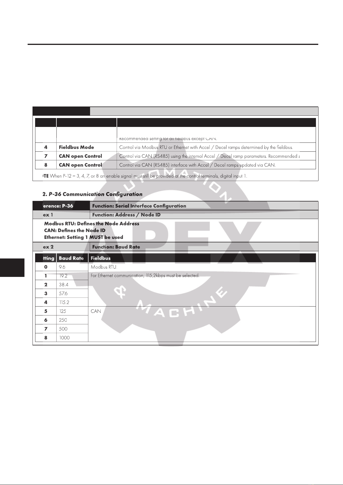
4.3. Modbus RTU Configuration Parameter
...........
10
4.4. Modbus RTU Status & Control Holding Registers
. .
10
4.5. Parameter Access
.............................
10
4.6. Modbus RTU Indirect Parameter Access
..........
10
5. CAN
.....................................
23
5.1. Overview
.....................................
11
5.2. CAN Communication Configuration Parameter
...
11
5.3. CAN COB-ID
................................
11
5.4. PDO Default Mapping
.........................
12
5.5. PDO Transmission Type
. . . . . . . . . . . . . . . . . . . . . . . . .
12
5.6. CAN Specific Object Table
....................
12
5.7. Parameter Access
..............................
13
5.8. Additional Status Indices
.......................
13
6. Ethernet Connection
.......................
14
6.1. Available Interface Options
.....................
14
6.2. External Interface
..............................
14
6.3. Internal Interface for IP66 Drives
................
16
6.4. Optional Interface for Compact 2 Basic Drives
...
17
6.5. Drive Parameter Settings
. . . . . . . . . . . . . . . . . . . . . . . .
17
7. Internal Webserver
........................
18
7.1. Overview
.....................................
18
7.2. Default Login
..................................
18
7.3. Web Server Contents
..........................
18
7.4. Changing the IP Address
. . . . . . . . . . . . . . . . . . . . . . . .
20
7.5. Creating an Additional User Account for Limited
Access
...........................................
21
8. Ethernet/IP Communication
................
22
8.1. Overview
.....................................
22
8.2. Operation
....................................
22
8.3. Usage Requirement
............................
22
8.4. Operation
....................................
23
8.5. Process Data Exchange (cyclic communication)
...
23
8.6. Configuring the Scanner
.......................
23
8.7. Advanced connection methods
..................
40
8.8. Parameter data transfer
........................
41
8.9. Trouble Shooting
..............................
43
9. Modbus TCP
..............................
45
9.1. Overview
.....................................
45
9.2. Usage Requirement
............................
45
9.3. Operation
....................................
45
9.4. Trouble Shooting
..............................
45
10. Fieldbus Gateways
.......................
47
10.1. Gateway Concept
............................
47
10.2. Gateway Included Components
...............
47
10.3. Gateway Installation
..........................
47
10.4. Subnetwork Connection
......................
48
10.5. Gateway Memory Mapping
..................
49
10.6. Controlling the Optidrive(s)
....................
50
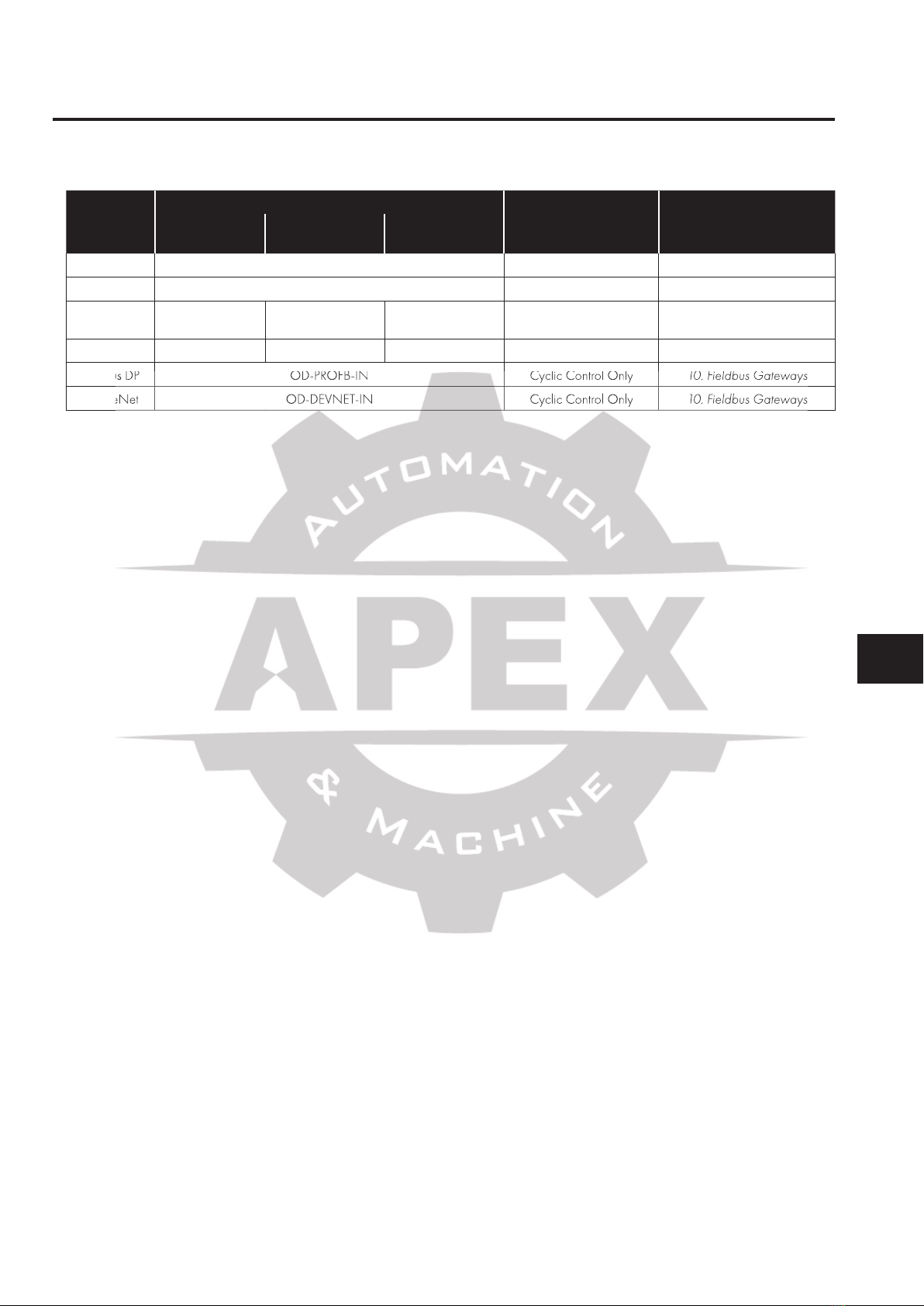
10.7. Profibus DP Gateway Features – OD-PROFB-IN
.
51
10.8. DeviceNet Gateway Features – OD-DEVNT-IN
.
52
10.9. Diagnostics and Troubleshooting
...............
53
11. Control & Status Registers
.................
54
11.1. Control Registers
..............................
54
11.2. Standard Status Registers
......................
55
11.3. Extended Status Registers
......................
56
11.4. Additional Modbus RTU Registers / CAN Index
Data – Control & Monitoring
.......................
57
12. Technical Data (External Interface)
.........
61
12.1. Environmental
................................
61
.....................................
.........................
4.3. Modbus RTU Configuration Parameter
4.4. Modbus RTU Status & Control Holding Registers
.............................
4.6. Modbus RTU Indirect Parameter Access
.....................................
.....................................
5.2. CAN Communication Configuration Parameter
................................
.........................
5.5. PDO Transmission Type
. . . . . . . . . . . . . . . . . . . . . . . . .
5.6. CAN Specific Object Table
..............................
5.8. Additional Status Indices
6.1. Available Interface Options
..............................
6.3. Internal Interface for IP66 Drives
6.4. Optional Interface for Compact 2 Basic Drives
6.5. Drive Parameter Settings
..............................
.....................................
............................
....................................
..............................
............................
10.2. Gateway Included Components
10.3. Gateway Installation
..........................
10.4. Subnetwork Connection
10.5. Gateway Memory Mapping
10.6. Controlling the Optidrive(s)
10.7. Profibus DP Gateway Features – OD-PROFB-IN
10.8. DeviceNet Gateway Features – OD-DEVNT-IN
10.9. Diagnostics and Troubleshooting
11. Control & Status Registers
..............................
11.2. Standard Status Registers
11.3. Extended Status Registers
11.4. Additional Modbus RTU Registers / CAN Index
Data – Control & Monitoring