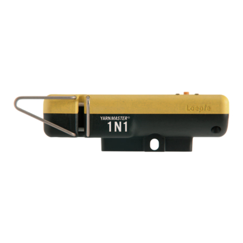
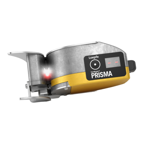
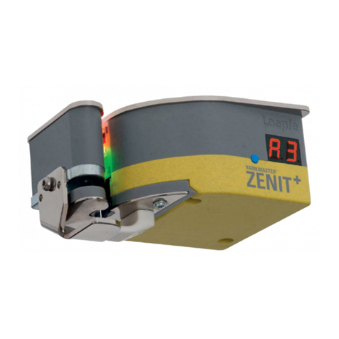
Loepfe YarnMaster Zenit User manual

YARNMASTER ®
ZENIT
Instruction Manual
LZE
044843.003en


Loepfe Brothers Ltd.
Kastellstrasse 10
P. O. Box 582
CH-8623 Wetzikon/Switzerland
Phone +41 43 488 11 11
Fax +41 43 488 11 00
E-Mail service@loepfe.com
Internet www.loepfe.com
YarnMaster®is a registered trademark of Loepfe Brothers
Ltd. for Switzerland and other countries.
All further company and product names are trading names or
registered trademarks of the relative companies.
The content of this Operating Instruction is protected by copy-
right. All rights reserved. No part of this may be reproduced in
whatever form (by printing, photocopying, microfilm or other)
without a written grant of Loepfe Brothers Ltd., nor may it be
processed or distributed by any electronic mean.
Copyright©2010 Loepfe Brothers Ltd., Switzerland
06.2011 / Version ≥ 2.3.2.3


ZENIT 5
TABLE OF CONTENTS
Table of Contents
Safety Instructions 7
Norms and Regulations 7
Instruction Manual 7
Liability 7
Operational Notes 8
Yarn Clearing (General) 9
Definition of Yarn Faults 9
Yarn Fault Classification 11
Yarn Clearing 12
Foreign Matter (F) 15
Synthetic Foreign Matter (P) 15
Variable CV Channel (VCV) 15
Imperfections 16
Surface Index SFI 16
YarnMaster Zenit 17
Functional Range 17
Operating 18
Central Unit 18
User Interface 19
Defining the Clearer Parameters 21
Defining the Class Settings 21
Assigning Changed Settings 22
Print 23
Adjust 24
Dialog 26
Software 26
Language 26
Reports 26
Reboot System 26
Machine 26
Central Unit 26
Date / Time 26
Access Level / Password 27
Configuration 28
System 28
Section 29

6ZENIT
TABLE OF CONTENTS
Group 30
Samples 31
Style (Style Memory) 32
Base Settings 34
Repetitions 34
Pilot Spindles 35
Data Acquisition 35
Reset Data 35
Diameter Base (Group) 36
Fine Adjust 36
Special Functions 37
Configuration Codes 38
Test Mode 39
Yarn Structure 42
Channel 42
Off Count 43
Short Off Count 43
Yarn Count 44
Short/Long/Thin Cluster 44
SFI/D (Option) 46
VCV (Option) 47
Splice 48
MM Lot 49
Setting Examples (Standard Values) 50
Class Clearing 51
Foreign Matter (F) 53
F Class Settings 53
F Cluster Settings 54
P Settings 55
Monitoring Data 56
Cut Data 56
Selection 57
Cut Declaration 57
Variable CV (Option) 59
Surface Index SFI (Option) 59
Imperfections IPI (Option) 60
Class Data 61
Class Clearing Data 61
F Clearing Data 62
Splice Classification Data 62
Chart 63
Shift Calendar 64
Diagnosis 65
AWE Zenit State / Adjust Parameters 65
AWE Command 65
Diameter Base (Spindle) 65
Spindle Adjust 65
Cut Declaration 65
Reports and Diagnosis 66
Checks and Maintenance 70
General 70
Daily 70
Weekly 70
Cleaning the Optics 71
Replacement of AWE or Sensing Head 71
Service Functions 72
Screen Calibration 72
Change of IP Address 72
Factory Reset 73
Reset of Fine Adjust Values 73
Clearer Components 74
Central Unit LZE-II 74
Central Unit LZE-III 75
Sensing Head 76
Yarn Count Rage (Optical scanning principle) 76
Sensing Head Display (7-Segment Display) 77
Mounting of P-Sensors 77
Technical Data 78

ZENIT 7
SAFETY INSTRUCTIONS
Safety Instructions
Norms and Regulations
The LOEPFE YarnMaster Zenit yarn clearing system is a prod-
uct which has been inspected for technical safety. It complies
with the following directives:
2006/42/EC Machinery Directive
2006/95/EC Low Voltage Directive
2004/108/EC Electromagnetic Compatibility
Instruction Manual
To prevent faults and operating errors, we recommend to
carefully read this Instruction Manual and to carefully follow
the instructions given.
!Indicates warnings which, if not properly observed,
could harm your health, impair the functioning of
the equipment or the security of your data.
Note : The screen representations in this manual serve as illus-
tration only. They should not be used as setting examples!
A copy of this Instruction Manual must be kept easily acces-
sible near the machine.
Liability
The manufacturer assumes no liability for damage caused by:
Noncompliance with the safety, operating and mainte-
nance instructions contained in this Manual.
The use of spare parts / non-OEM parts / conversion parts
not supplied by us.
Unauthorized conversion and modification of the yarn
clearer.
Normal wear.

8ZENIT
SAFETY INSTRUCTIONS
!
!
!
!
Operational Notes
This yarn clearing equipment must only be installed, initiated
and operated by trained personnel. Improper operation of the
equipment could cause hazards.
In accordance with 2006/42/EC, 2006/95/EC, 2004/108/EC
this yarn clearing installation should only be operated with the
covers closed (cooling, fire protection, contamination, spark
interference etc.)
This yarn clearing equipment must only be operated with
the standard power supply (voltage/cycles) with ground con-
nection.
AC 110V 60Hz 3.15 A -15%/+20%
AC 230V 50Hz 3.15 A ±15%
As per other information by the machinery manufacturer,
however, with ground connection and with an isolation
transformer which complies with the requirements of DIN
EN 61558.
The ON/OFF switch does not disconnect the equipment
from the mains voltage! Failure to comply with this
warning can result in death or severe injuries.
Before opening, modifying or completing the equipment,
disconnect the mains plug from the grounded power supply
socket or turn off the master switch of the winding machine.
This yarn clearer system may be connected to the power sup-
ply only after installation of all front panels, plug-in boards and
provided covers, in particular of the central unit.
Under certain conditions, high temperatures may occur at the
power print of the control station. Check the temperature be-
fore touching the cooling rips.
The knives at the sensing heads are automatically activated.
Beware of touching the knives, you could be injured.
Electronic components and assemblies (printed circuit
boards) are endangered by electrostatic charges! Be-
ware of touching the soldered connectors, pin contacts, print-
ed circuits or electronic components before they have been
discharged statically. Hold the units at the periphery only.

ZENIT 9
YARN CLEARING GENERAL
Yarn Clearing (General)
Definition of Yarn Faults
The spinning process supplies a relatively uniform yarn.
However, differences in yarn diameter cannot be completely
avoided. Thus, it is first necessary to distinguish between
normal yarn irregularities and actual yarn faults.
Yarn faults may be defined as yarn irregularities which can
lead to difficulties in subsequent production stages or to
faults in the end product. Yarn clearing is defined as the de-
tection and elimination of yarn faults. This task is performed
during the winding process. Yarn clearer are, therefore, part
of a winder.
To eliminate a fault it is necessary to interrupt the winding
process. The spindle must be stopped, the fault eliminated
and the ends of the yarn joined together again. Obviously this
interruption results in a loss of production. Yarn clearing is,
therefore, always a compromise between quality and produc-
tion, i.e. between the maximum possible number of yarn faults
which could be removed and the least acceptable production
loss. This compromise results in a distinction between:
Objectionable yarn faults, namely those which are
tolerated for sake of machine efficiency, and
Non objectionable yarn faults, faults that cannot be
tolerated.
Yarn Faults
Based on the average yarn diameter (basic diameter), the fol-
lowing yarn faults can be detected and cleared:
Thick and thin places are defined, depending on wheth-
er there is an increase or a decrease in diameter.
Within the thick places further distinctions are made:
– Neps, as extremely short (up to a few mm) and extre-
mely thick faults (several times the base diameter)
– Short faults, as faults of limited length (of about 0.5 to
10 cm) but of considerable thickness (1.1 to 4.0 times the
base diameter)
– Long faults and double ends, as faults of considerable
length (from 5 to 200 cm) but of limited thickness (1.04 to
2.0 times the base diameter).
Faulty splices
Yarn count deviation (positive / negative)
in the short count range (1–32 m)
Neps
Short Faults
Long Faults
Thin Places
Splices
Yarn Count
Short Count
10 ZENIT
YARN CLEARING GENERAL
Accumulations of Faults (Cluster)
Periodic clusters (moiré)
Non-periodic clusters
in the short, long or thin fault range which repeat them-
selves several times within a short distance.
Off-standard Bobbins (SFI / D)
Irregularities of the surface structure such as:
Hairiness
Neppiness
Irregularity
Imperfections (IPI)
Yarn Irregularities (VCV)
Disturbing diameter variations or sporadic irregularities, for
example:
Neppiness
Irregularity (CV)
Imperfections (IPI)
Check length adjustable between 1–50 m
Foreign Matter (F)
Foreign matter with a color that is different from the base
color of the yarn:
Bright foreign matter in the dyed yarn
Dark foreign matter in the raw-white yarn
Even the smallest contrast differences are reliably detect-
ed in colored yarns.
Synthetic Foreign Matter (P)
Synthetic foreign matter (e.g. polypropylene)
Irrespective of the color of the yarn and the foreign
matter, for example, white and transparent polypropyl-
ene in raw-white yarn
In dyed or colored yarn In raw-white yarn
Periodic
Non-periodic
Hairiness
Neppiness
Irregularity
Imperfections
Neppiness
Irregularity
Imperfections
Synthetic foreign matter in raw-white yarn

ZENIT 11
YARN CLEARING GENERAL
Figure 1
Diameter Y
Length X
Figure 2
Length
Figure 3
Yarn Fault Classification
Yarn faults are defined in terms of a transverse dimension
and a longitudinal dimension. The transverse dimension is ex-
pressed as a multiple of the base diameter and the longitudinal
dimension in centimeters.
The definition of yarn faults in terms of length and thickness
suggests the representation of yarn faults in a Cartesian sys-
tem of coordinates. Thereby the length is plotted in the hori-
zontal direction (X-axis), and the thickness in the vertical direc-
tion (Y-axis). Each yarn fault can, thus, be plotted as a point in
the plane of the coordinates. Furthermore, the plane of the co-
ordinates can be divided into individual fields (classes) in order
to summarize (classify) similar yarn irregularities into groups
and to count them. This takes into account another extremely
important point of view, namely the frequency of similar faults
(see figure 1) Frequency distribution of yarn faults in the coordinate grid
The choice of the class limits is largely random. Short faults
are most frequently divided into 16 thickness classes (see
figure 2).
The classification scheme can be extended to include addi-
tional classes for long faults and thin places. The YarnMaster
System uses the following classification (see figure 3).
Diameter
2 2 2 4 2 4 2 8
1 1 1 3 1 3 1 7
2 2 2 4 2 4 2 6
1 1 1 3 1 3 1 5
2 2 2 4 2 4 2 4
1 1 1 3 1 3 1 3
2 2 2 4 2 4 2 2
1 1 1 3 1 3 1 1
3 3 6 3 6 9 3 6
2 2 5 2 5 8 2 5
1 1 4 1 4 7 1 4
1 1 2 1 2 3 1 2
1 1 2 3 1 2 1 2
1 1 3 5 1 3 1 3
2 2 4 6 2 4 2 4
1 1 2 3 1 2 1 2
N4 A4 B4 C4 D4
N3
N2
N1
A3 B3 C3 D3
D2
A2 B2 C2
A1 B1 C1 D1
C0 F G
G00
F00C00 D00
-C0 -D0
-D1
H0
-C1 H1
I0
I1
I2H2
-D2-C2
D0
E
7.00
5.00
3.90
3.20
2.70
2.30
2.10
1.80
1.60
1.45
1.30
1.20
0.83
0.80
0.75
0.65
0.5 1.0 1.5 2.0 3.0 4.0 6.0 8.0 12.0 20.0 32.0 70.0

12 ZENIT
YARN CLEARING GENERAL
As already mentioned, various types of yarn faults are distin-
guished according to their form. In the plane of coordinates it
is possible to distinguish areas which relate to the following
types of faults (see figure 4).
Neps Thick places / Short faults
Long faults and
Double ends
Thin places
Figure 4
Figure 5
Diameter
Length
RG
Yarn Clearing
Base Curve
The distinction between yarn faults which are to be cut out
and those which are to be left in the yarn (unacceptable and
acceptable yarn faults), which is made in the interest of win-
der efficiency, has already been pointed out. This distinction
can be represented graphically on the plane of coordinates as
a line which separates the acceptable faults (below) from the
unacceptable ones (above). This line represents the theore-
tically-desirable base curve (RG). A concave base curve
(see figure 5) normally corresponds to the requirements in
practice.
The concave shape arises from the textile evaluation, where-
by the greater the deviation in diameter that is tolerated, the
smaller the length deviation that appears acceptable. Fur-
thermore, the base curve, thus, passes through fields of sim-
ilar fault frequencies, which meets the requirement of high
efficiency.
A distinction must be made between the theoretically-desir-
able base curve and the practically-achievable base curve,
which depends on the one hand on the clearing characteristic
typical of a clearer type, and, on the other hand, on its set-
ting flexibility.

ZENIT 13
YARN CLEARING GENERAL
Clearer Characteristics
Clearer characteristics are the basic pattern of the base curve,
this pattern being typical of a particular clearer type. Impor-
tant factors in assessing a clearer are the shape of this base
curve on the one hand, and the possibility of changing this
curve on the other hand.
The corresponding clearer setting:
N = 6.0 Diameter limit for neps
DS = 2.40 Diameter limit for short faults
LS = 1.3 Limit for short fault length
DL = 1.25 Diameter limit for long faults and double ends
LL = 40 Limit for long fault length
-D = -20% Limit of the diameter decrease for thin places
-L = 60 Limit for thin place length
All diameter limits refer to the reference yarn diameter
(base).
Clearing According to Classes
Yarn Faults
Clearing according to classes allows for the creation of com-
pletely optional clearer characteristics. This is advantageous,
especially for fancy yarns.
The use of class clearing in combination with conventional
clearing often achieves better results when short and long
faults occur at the same time.
Splices
Clearing according to splice classes allows for the creation of
completely optional splice detection. An advantage for fancy
yarn, core-spun yarn etc.
Graphic presentation of clearing curve

14 ZENIT
YARN CLEARING GENERAL
Short Fault and Long Fault Combined
Exact inspection of a yarn fault shows that it changes along
the longitudinal dimension. A thick place is made up of a com-
bination of different thickenings.
For classification, this fault is only characterized after it has
completely run through the measuring field of the sensing
head.
The different cross dimensions of the long fault are calculated
as a mean value. The average thickening is then lower relative
to the largest cross-dimension of the yarn fault. Therefore the
yarn fault is assigned to the long fault class.
Depending on the yarn and the selected setting it is therefore
possible that, at simultaneous short and long faults, the sum
of the cut short and long faults in menu Monitoring Data and
the sum of the cut short and long faults in menu Class Data
show differences.
For simultaneous short and long faults it is recommended to
apply the class clearing in combination with the conventional
clearing. Better results can thus be achieved.
Characterized as short
when cleared according to channels
Base curve set
with respect to short
Characterized as long during classification

ZENIT 15
YARN CLEARING GENERAL
Foreign Matter (F)
The classification of foreign matter is based on the evaluation
of differences in contrast.
Foreign matters are classified as follows: The length class-
es on the horizontal axis are divided into S–I–R–O, the dark-
ness levels on the vertical axis into 1–2–3–4. In addition, each
class is divided into four subclasses. (= total 128 classes).
The darkness scale is divided into a positive area (darker color
positions) and a negative area (for brighter color positions).
Synthetic Foreign Matter (P)
The detection of synthetic foreign matter as polypropylene,
polyamide (nylon) etc. is based on Triboelectricity. The differ-
ent electrical charging of materials (e.g. cotton and polypro-
pylene) caused by the winding process is evaluated.
Triboelectric Effect
The triboelectric effect is an electrical phenomenon
where certain materials become electrically charged after
coming into contact with another, different, material.
The polarity and strength of the charges produced differ
according to material and surface smoothness.
That means: The further the materials lie off each other in the
triboelectric series, the more definitely they can be detected.
Variable CV Channel (VCV)
Disturbing diameter variations caused by draft faults, soiled
cylinders or sporadically occurring irregularities can be de-
tected.
As opposed to laboratory practice where check lengths of
400 or 1000 m are normally used for CV determination, the
check length of the VCV can be varied continuously between
1 and 50 m. This allows for the specific detection of diameter
variations in this length range.
The clearer calculates continuously the VCV values from the
yarn pieces with the set check length and compares these
with its floating mean value.
Note : These values cannot be compared with the optical CV
values of the Statistics or the data collected in the laboratory
because the check lengths as well as the cutting lengths for
calculation are different.
Dark
Bright
2 4 2 4 2 4 2 4
1 3 1 3 1 3 1 3
2 4 2 4 2 4 2 4
1 3 1 3 1 3 1 3
2 4 2 4 2 4 2 4
1 3 1 3 1 3 1 3
2 4 2 4 2 4 2 4
1 3 1 3 1 3 1 3
1 3 1 3 1 3 1 3
2 4 2 4 2 4 2 4
1 3 1 3 1 3 1 3
2 4 2 4 2 4 2 4
1 3 1 3 1 3 1 3
2 4 2 4 2 4 2 4
1 3 1 3 1 3 1 3
2 4 2 4 2 4 2 4
BS1 BI1 BR1 BO1
BO2
BO3
BO4
BR2
BR3
BR4
BI2
BI3
BI4
BS2
BS3
BS4
DS4
DS3
DS2
DS1
DI4
DI3
DI2
DI1
DR4
DR3
DR2
DR1
DO4
DO3
DO2
DO1
1
2
3
4
ORIS
4
3
2
1
MASTERS IN TEXTILE QUALITY CONTROL
TRIBOELECTRIC SERIES
Dry Human Hands, Skin
Leather
Rabbit Fur
Glass
Human Hair
Nylon (Polyamid)
Wool
Fur
Lead
Silk
Aluminium
Paper
Cotton
Steel
Wood
Amber
Hard Rubber
Nickel, Copper
Brass, Silver
Gold, Platinum
Polyester
Saran Wrap
Polyacrylic
Polyurethane
Polyethylene (scotch tape)
Polypropylene
Acquires a more
positive charge
+
+
-
–
Acquires a more
negative charge
Triboelectric Series

16 ZENIT
YARN CLEARING GENERAL
Imperfections
Frequent yarn faults are described as Imperfections in the
language of the textile industry. It is generally acknowledged
that the shorter the fault length, or the smaller the diameter
deviation respectively, the more frequent the event.
The source of these faults is found in the raw material or in a
non-perfect spinning process. The raw material, card wires,
eccentric top rollers/bottom rollers, defective aprons, rings
and ring travellers have a significant influence on the imper-
fections.
With a reliable analysis of the Imperfections it is not only
possible to optimize the production process but also con-
clusions can be drawn concerning the quality of the used
fibre material.
20 70 cm
0.5 1 2 4 8 cm
D 5.00
D 3.20
D 2.30
D 1.81
D 1.28
D 0.89
D 0.75
D 1.11
Surface Index SFI
The monitoring and evaluation of the surface structure of a
yarn (e.g. hairiness), is a further important criterion for qual-
ity assurance.
In order to predict yarn behavior during processing in weav-
ing or knitting, it is not sufficient to simply consider individual
quality characteristics (e.g. yarn irregularity) to assess a yarn.
Only a combination of different quality criteria (e.g. hairiness
and irregularity) supports making a definite conclusion.
These quality characteristics are combined in the surface in-
dex SFI enabling the user to monitor the quality level easily
and efficiently.
Frequent events Neps
Thick Places
Thin Places
Very frequent events Small

ZENIT 17
FUNCTIONAL RANGE
YarnMaster Zenit
Functional Range
P Clearing
– Clearing of Synthetic Foreign
Matters PP PE etc.
F Clearing
– Foreign Matter Class Clearing dark
and bright
– Foreign Matter Cluster Clearing
LabPack (Option)
– Imperfections IPI
– Surface Index SFI
– Off-Standard Bobbin Detection SFI/D
– Variable CV Channel VCV
Quality Pack
– Channel Clearing
N Neps
S Short Faults
L Long Faults
T Thin Places
– Yarn Count Channel
– Short Count Channel
– Cluster Channel Long / Short / Thin
– Class Clearing
– Classification of Yarn Faults
– Splice Channel
– Splice Class Clearing
– Classification of Splice Faults
YARNMASTER
ZENIT
YARNMASTER
ZENIT F
YARNMASTER
ZENIT FP

18 ZENIT
OPERATING
Operating
Central Unit
1Touch Screen
The central unit is operated by direct inputs on the touch-
screen. Applying light pressure on the screen surface acti-
vates the functions shown.
Tap the menu item to be selected with the finger or a blunt,
non-metallic object.
!Do not use a pointed, metallic object as this could
damage the monitor surface!
Cleaning
The monitor surface is made of plastic material. Clean the
monitor with a soft cloth. Heavy soiling can be cleaned with
water and soap.
!Never clean the monitor with aggressive cleaning
agents!
2USB Port
USB port to transfer reports and clearer data to a server and
printer. The USB port is protected against dust and humidity
by a removable cover.
2
2
2
1
2

ZENIT 19
OPERATING
User Interface
1Menus (Overview)
Tapping the tabs in the header calls up the respective menus.
/ More menus are called up via the left or right arrow.
2 Class Window
Class settings and class clearing data are displayed in the
class window as follows:
Blue fields Class clearing
Purple fields Splice class cearing
Blue-yellow fields F-Cluster clearing
By tapping, the class window is displayed in an extended
mode and the class settings can be changed.
Curves
In the class window, the channel and the cluster or the splice
curve can be shown () or hidden ().
3Input Fields / Display Fields
The clearer settings and clearer data are displayed in groups.
Dark yellow fields Clearer settings
Light yellow fields Clearer data
Tapping an input field opens an input window and the clearer
settings can be changed. On some menus, additional input
fields become visible.
/
On some input fields, it is possible to activate or deactivate
a setting, a command or a display mode:
= active, = not
active.
Note : Menus or clearer functions that are not active are
grayed out.
3
1
2

20 ZENIT
OPERATING
Print
The clearer data or clearer settings of the open menu can be
saved to a USB flash drive and printed as PDF.
Group / Edit
The + or – keys or the “keyboard” called up can be used to
select a certain clearer group or spindle.
Depending on the menu, these keys are used to:
Select a clearer group or a memory to assign clearer set-
tings.
Select a clearer group to perform an adjustment.
Select a clearer group or an individual spindle to view the
clearer settings, classification data or production data.
4 Edit Field
Info
Menu navigation. Further steps to be performed are displayed
as input assistance.
Data Source
Display of selected group, selected spindle or selected
style memory.
Description of spooled lot or, if not defined, description of
the style.
Adjust
During the startup or the start of the lot, the clearer is cali-
brated to the new yarn. Adjustment is started, activated or
aborted here.
4
Table of contents
Other Loepfe Industrial Equipment manuals

Loepfe
Loepfe YarnMaster PRISMA User manual

Loepfe
Loepfe YARNMASTER 3N1 Install guide

Loepfe
Loepfe YARNMASTER 3N1 Install guide

Loepfe
Loepfe YARNMASTER 3N1 Install guide

Loepfe
Loepfe YARNMASTER 1N1 User manual

Loepfe
Loepfe YARNMASTER ZENIT+ User manual

Loepfe
Loepfe YARNMASTER 1N1 User manual

Loepfe
Loepfe YARNMASTER 3N1 Install guide