Sure-Feed Engineering ECO Series Application guide

Sure-Feed Engineering Inc.
SE-1200-EI
ECO-SERIES
Operation & Parts Manual

Sure-Feed
Engineering
Inc
1
SE 1200 EI
ECO-SERIES
OWNERS MANUAL
Table of Contents
1. Installation guide
2. Set-up instructions
3. Operation instructions
4. Cleaning
5. Troubleshooting
6. Parts manual
7. Electrical schematic
8. Warranty information

Sure-Feed
Engineering
Inc
2
SECTION 1
Sure-Feed Engineering Inc.
Installation Instructions
1. Before positioning the feeder on the inserter, follow the setup and
operating instructions completely. When you are confident the material
is feeding consistently, precede to the inserter preparation instructions
then the installation and set-up procedure.
2. Remove the rear guide from the inserter pocket.
3. Remove the bottom plate.
4. Remove the suction cup and loosen the separator feet, sliding them back and
to the furthest point sideways so as not to interfere with the path of the piece
to be inserted.
5. Cycle the inserter to the point where the gripper jaw is at the furthest point
forward in the stroke.
6. Bend the material guide tabs so that they align just above the surface of the
bottom gripper jaw.
7. Adjust the 3-leg sensor arm to position the sensor 1/2” above the paper path
and about 3/4 of the length of the piece ahead of the feeder.
8. Place 10 pieces in the feeder and turn the speed adjustment to the minimum
setting (counter-clockwise).
9. Plug the feeder into a 110 VAC grounded outlet.
10.Turn the power switch on.
11.By turning the speed control switch clockwise, advance the first piece until the
sensor is blocked and the feeder stops. If the sensor is not positioned
properly, the feeder will not stop. Adjust the height and angle of the sensor
until the feeder stops.

Sure-Feed
Engineering
Inc
3
Sure-Feed Engineering Inc.
Installation Instructions Cont’
12.Position the feeder on the inserter table so that the edge of the leading piece
is between the material guide tabs and the bottom of the front hopper plate.
13.Adjust the sensor so that the piece advances out further and is well within the
gripper jaw opening.
14.With the speed control set to minimum, jog the inserter to remove the piece
staged in the gripper jaw and return the gripper jaw to the furthest inward
position.
15.Turn the speed control up slightly. This should advance the next piece into
the gripper jaw. Adjust the sensor, material guide tabs and position the SE
1200 EI (Eco-Series) as needed to align the paper path into the gripper jaw.
16.Load the SE 1200 EI (Eco-Series) with at least a full handful of material and
cycle the inserter.
17.Notice the material path and the presentation to the gripper jaw, as this is
most important as the cycle speed is increased.
18.Cycle the inserter at full production speed adjusting the SE 1200 EI (Eco-
Series) speed so that the piece being presented to the gripper jaw is there
well ahead of the end of the forward stroke.

Sure-Feed
Engineering
Inc
4
SECTION 2
Sure-Feed Engineering Inc.
Set-up Instructions
1. With the feeder ON/OFF switch in the off position, loosen the two side guides
and move them all the way to the sides of the feeder. Then loosen the rear
guide ramp and move it all the way back out of the way.
2. Place a single piece of the material to be fed on the feeder centering the
material relative to the separating device.
3. Move each side guide in to meet the material and then back them off about
1/16”.
4. Tighten the bottom thumbscrews on each side guide.
5. Turn the separator knob clockwise until you can easily pass the single piece
of material under the separator. While moving the material back and forth
under the separator, turn the separator knob counter-clockwise until you feel
resistance from the separator. At this point, you have roughed in the
separator setting and will need to tune it in after the completion of the
following set-up steps. If the resistance under one separating wheel is not the
same as under the separating wheel, the bridge needs to be trammed.
Perform step 10 before proceeding with step 6.
6. Place a handful of material in the feeder allowing the material to shingle
forward into the separator.
7. Move the back guide forward so as to use the back guide wedge shape to
support the back edge of the material stack. At this point, you have roughed
in the back guide setting and will need to tune it in later.
8. Add enough material to the stack to fill about half the height of the side
guides.
9. Move the top of each side guide out slightly so as to create a funnel effect
and then tighten the top thumbscrews on each side guide. You are now ready
to feed some material.

Sure-Feed
Engineering
Inc
5
10.BRIDGE TRAM PROCEDURE: It is critical to the performance of the feeder
to have the separating wheels level with respect to the nip rollers. To do this,
first loosen the bridge mounting screws (Item 8, Fig. 6-3) on both sides of the
bridge. Turn the separator adjustment CW several turns so that the bridge
can be lowered all the way to the bottom of the slots. Tighten one screw on
each side. Now place a thin strip of paper under each separating wheel (it is
best to cut one piece of paper into two strips to ensure that the strips are the
same thickness). Now turn the separator adjustment CCW until the
separating wheels just contact the nip rollers. Move the paper strips to feel if
the resistance is equal under each separating wheel. If one moves with less
resistance than the other, loosen the screw on the side that is tighter and
raise that side of the bridge slightly and tighten screw. Check the resistance
under each separating wheel with the paper strips again and adjust
accordingly. Once the resistance is equal under each separating wheel
tighten the bridge screws securely. Proceed to step 6 for further setup
instructions. This procedure must be followed whenever the bridge is
adjusted up or down for materials with different thickness. This adjustment is
“very” critical when feeding thin materials.

Sure-Feed
Engineering
Inc
6
SECTION 3
Sure-Feed Engineering Inc.
Operation Instructions
1. Adjust the 3-leg sensor arm to position the sensor 1/2” above the paper path
and about 3/4 of the length of the piece ahead of the feeder.
2. With the power still off, turn the speed control counter-clockwise to the
minimum position.
3. Turn the power switch on and turn the speed control switch clockwise, the
first piece will advance until the sensor is blocked and the feeder stops. If the
sensor is not positioned properly, the feeder will not stop. Adjust the height
and angle of the sensor until the feeder stops.
4. Cycle the feeder by removing the piece that block the sensor. Observe the
consistency in which the material is feeding.
5. By turning the separator knob slightly in either direction, you will change the
way the material is separating.
6. By moving the back guide in and out, you will quickly find the position that
creates the most consistent separation.
7. One important item to note; There is no substitution for experience. By
working with the SE 1200 EI (Eco-Series), you will notice that the combination
of separator setting and the back guide adjustment together will have the
greatest effect on separation. Generally, the longer the piece of material, the
flatter the material stack should be. Conversely, the shorter the piece of
material, the closer the back guide adjustment should be to the material,
adding wedge to the material stack. You will also notice that by moving the
back guide forward (increasing the wedge), you can open the separator and
still achieve good separation.

Sure-Feed
Engineering
Inc
7
SECTION 4
Sure-Feed Engineering Inc.
Cleaning Instructions
Clean rollers and belts are very important to the performance of the feeder. Use
a clean rag dampened with Isopropyl Rubbing alcohol, 70% by volume (typically
available in drug stores) to clean belts and rollers. Do not use any other solvents,
cleaners, or abrasive cleaners on the rollers or belts as they may damage the
rubber.
Warning: Isopropyl rubbing alcohol is very flammable! Always unplug
the machine before cleaning belts and rollers. DO NOT! use near an open
flame, sparks, or any other source of ignition. DO NOT! smoke in the
vicinity of the alcohol fumes. Allow used rags to air-dry before throwing
them in the trash. Dispose of used rags properly.
Other areas of the machine should be wiped clean with a clean dry rag.

Sure-Feed
Engineering
Inc
8
SECTION 5
Sure-Feed Engineering Inc.
Troubleshooting Guide
Problem
Solution
Feeder will not run.
Check circuit breaker condition.
Check outlet power source.
Check power switch.
Feeder runs but no material is being
dispensed.
Check material supply.
Remove all material and follow setup
procedure.
Check rollers and belts for excessive
wear or dirt.
Feeder does not create a gap
between pieces.
Lower separator adjustment and
observe. If a gap is not present after this
adjustment, return separator to original
position and move the back guide
forward.
Feeder does not detect material.
Adjust position of the sensor.
Thick material does not feed well.
Decrease the height at the back of the
material stack.
Increase the opening at the separation
device (the thicker the material the less
critical the setting is).

Sure-Feed
Engineering
Inc
9
Sure-Feed Engineering Inc.
Troubleshooting Guide Cont.
Problem
Solution
Thin material does not feed.
Adjust separation device as described in
section 2.
Remove material and fan the stack
allowing air to separate the pieces.
Raise the rear of the material stack by
moving the wedge forward.
Material feeds double.
After confirming set up is correct,
remove the separator and inspect the o-
rings. If the o-rings are worn past the
depth of the groove in the separating
wheel, they will not be effective. Rotate
the o-ring in the groove until a new
section of o-ring is in position to contact
the material. Reinstall the separator and
reset the gap.

Sure-Feed
Engineering
Inc
10
SECTION 6
Sure-Feed Engineering Inc.
Parts Manual

Sure-Feed
Engineering
Inc
11
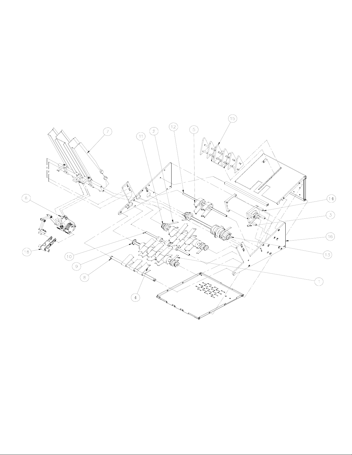
FEEDER ASSEMBLY (fig. 6-1)
ITEM
FIGURE
QTY.
DESCRIPTION
1
99000-001
1
BELT, TIMING, 90XL
2
99000-002
1
BELT, TIMING, 110XL
3
99000-003
1
BELT, TIMING, 120XL
4
99000-004
3
BELT, RED GUM
5
99000-005
2
BELT, ELEVATOR
6
6-2
1
SEPARATOR DEVICE ASSEMBLY (ECO-SERIES)
7
6-3
1
SIDE GUIDE ASSEMBLY
8
6-4
1
FRONT SHAFT ASSEMBLY
9
6-4
1
NIP ROLLER SHAFT ASSEMBLY
10
6-4
1
SUPPORT IDLER SHAFT ASSEMBLY
11
6-4
1
MAIN SHAFT ASSEMBLY
12
6-5
1
ELEVATOR SHAFT ASSEMBLY
13
6-6
1
CLUTCH SHAFT ASSEMBLY
14
6-6
1
MOTOR ASSEMBLY
15
6-7
1
PAPER SLIDE ASSEMBLY
16
6-8
1
CHASSIS ASSEMBLY
17
6-9
1
ELECTRICAL COMPONENT ASSEMBLY (NOT SHOWN)
18
6-10
1
TRAILING ARM ASSEMBLY
Sure-Feed
Engineering
Inc
12
FIG. 6-1

Sure-Feed
Engineering
Inc
13
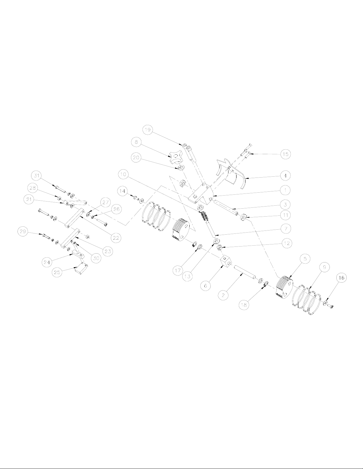
1200EI-ECO SEPARATOR DEVICE ASSY (Fig. 6-2)
ITEM
PART NO.
QTY.
DESCRIPTION
1
10007-002
1
BLOCK, FOOTBALL SEPARATOR
2
10004-059
1
SHAFT, FOOTBALL ALIGNING
3
10004-058
1
SHAFT, FOOTBALL SEPARATOR
4
10005-025
1
SHROUD, SEPARATOR
5
10007-005
2
BLOCK, FOOTBALL.
6
10007-012
1
BLOCK, SEPARATOR ADJUSTING
7
10004-028
1
STUD, SEPARATOR ADJUSTING
8
99004-001
1
KNOB 5/16-24 FE
9
10014-010
8
O-RINGS, FOOTBALL SEPARATOR
10
10019-002
1
SPRING, COMPRESSIOM (FOOTBALL)
11
10012-005
2
SPACER, FOOTBALL SEPERATOR
12
1
NUT, HEX 5/16-24
13
2
WASHER, FLAT 5/16
14
2
SCREW, PAN HD 10-24 X 3/8
15
3
SCREW, FL HD 8-32 X 1
16
2
WASHER, FLAT, #10
17
99003-017
2
WASHER, NYLON 3/8 ID X 1/16
18
99022-003
2
SNAP RING, 3/8
19
2
BOLT, SOCKET HD, 5/16-18 X 2 1/2
20
99003-015
1
WASHER, NYLON, 5/16 X 1/16

Sure-Feed
Engineering
Inc
14
1200EI-ECO SEPARATOR DEVICE ASSEMBLY CONT’ (fig. 6-2)
21
10009-011
1
ARM, SENSOR
22
10009-007
1
ARM, SENSOR
23
10009-008
1
ARM, SENSOR
24
10009-009
1
MOUNT, SENSOR
25
98009-001
1
SENSOR, RECIEVER
26
4
WASHER, LOCK #10
27
7
WASHER, FLAT, #10
28
2
NUT, LOCK, 10-24
29
1
SCREW, SKT HD, 10-24 X 3/4
30
2
SCREW, SKT HD, 6-32 X 1/2
31
3
SCREW, PAN HD, 10-24 X 1-1/4
Sure-Feed
Engineering
Inc
15
FIG. 6-2

Sure-Feed
Engineering
Inc
16
SIDE GUIDE ASSEMBLY (Fig. 6-3)
ITEM
PART NO.
QTY.
DESCRIPTION
1
10009-002
2
BRACKET, SIDE GUIDE MTG
2
10003-003
1
CROSS BAR, SE-1200-EI
3
10005-009
1
GUIDE, SIDE, RH (TALL)
4
10005-002
1
GUIDE, FRONT PAPER (TALL)
5
10005-008
1
GUIDE, SIDE, LH (TALL)
6
10005-014
1
GUIDE, BUSINESS, RH (TALL)
7
10007-008
2
BLOCK, BUSINESS GUIDE MTG
8
10005-015
1
GUIDE, BUSINESS, LH (TALL)
9
99004-002
6
KNOB, #10 SCREW
10
8
SCREW, SKT HD, 10-24 X 1/2
11
4
SCREW, BTN HD, 10-24 X 1/2
12
4
SCREW, FLAT HD, 10-24 X 3/8
13
8
SCREW, FLAT HD, 8-32 X 1/2
14
4
SCREW, FLAT HD, 6-32 X 1/2
15
10007-010
1
BLOCK, SEPARATOR ADJ
16
99004-003
2
HANDLE, RATCHET, 10-24
17
10007-007
2
BLOCK, BUSINESS GUIDE MTG (UPPER)

Sure-Feed
Engineering
Inc
17
FIG. 6-3

Sure-Feed
Engineering
Inc
18
SHAFT ASSEMBLIES (Fig. 6-4)
ITEM
PART NO.
QTY.
DESCRIPTION
1
10004-009
1
SHAFT, FRONT, SE-1200-EI
2
10004-123
1
SHAFT, NIP ROLLER, 3/4 (1200 EI)
3
10004-045
1
SHAFT, MAIN, SE-1200-EI
4
10004-046
1
SHAFT, SUPPORT IDLER, SE-1200-EI
5
10006-070
2
NIP ROLLER, 3/4 BORE
6
10006-071
3
PULLEY, MATE, 3/4 BORE
7
10006-014
3
PULLEY, CROWNED
8
10006-007
2
FEEDER, ROLLER
9
10006-012
3
ROLLER, IDLER
10
99002-006
1
PULLEY, 24XL037
11
99002-003
2
PULLEY, 20XL037
12
99000-005
3
BELT, RED GUM
13
99000-001
1
BELT, TIMING, 90XL037
14
99003-083
4
BEARING, 1/2 X 1-1/8, SHIELDED W/ S.R.
15
99003-001
6
BEARING, SHIELDED, 3/8 X 7/8
16
99022-004
2
SNAP RING, 1/2
17
99003-018
5
WASHER, NYLON, 1/2 X 1/16
18
99022-003
6
SNAP RING, 3/8
19
99003-056
2
BEARING, SEALED, 1/4 X 5/8
20
16
SET SCREW, 10-24 X 3/8
21
6
SET SCREW, 8-32 X 3/8
22
2
SCREW, FLAT HD, 8-32 X 1/2
23
10006-069
2
FEEDER ROLLER, 3/4 BORE
24
10006-021
2
PULLEY, DRIVE, 22XL875

Sure-Feed
Engineering
Inc
19
FIG. 6-4
This manual suits for next models
1
Other Sure-Feed Engineering Industrial Equipment manuals


Popular Industrial Equipment manuals by other brands


Siemens
Siemens 3TL61 operating instructions

Hammerhead
Hammerhead 100XTR Operator's manual

SAMCHULLY
SAMCHULLY PHD instruction manual

FläktGroup
FläktGroup ECONET Installation & maintenance manual

6K Products
6K Products DH0606 Operation and parts manual

Schrempp electronic
Schrempp electronic MG-3-T4-TRIO IOL M8 manual