WPG FLEXR Series User manual

Rev 5.1/4-21 FLEXR(L)-HV11AIR: #350361
INTENDED FOR USE BY SKILLED
PROFESSIONALS • READ AND
UNDERSTAND BEFORE OPERATING
OPERATING
INSTRUCTIONS 908 W. Main • P.O. Box 368
Laurel, MT USA 59044
800-548-7341 (phone)
406-628-8231 (phone)
406-628-8354 (fax)
www.WPG.com
Record serial number in blank space above (to locate, see serial
label on the product).
FLEXR(L)SERIES
FLAT LIFTER,
AIR-POWERED
Model numbers: FLEXR4HV11AIR,
FLEXR6HV11AIR, FLEXRL6HV11AIR (shown)
KEEP FOR FUTURE REFERENCE

FLEXR(L)-HV11AIR: #35036 Rev 5.1/4-212

Rev 5.1/4-21 FLEXR(L)-HV11AIR: #350361
SPECIFICATIONS .....................................................................................3
SAFETY...................................................................................................5
OPERATING FEATURES............................................................................6
ASSEMBLY..............................................................................................7
INTENDED USE .......................................................................................9
LOAD CHARACTERISTICS.................................................................................9
OPERATING ENVIRONMENT..........................................................................10
DISPOSAL OF THE LIFTER .............................................................................10
OPERATION..........................................................................................11
BEFORE USING THE LIFTER...........................................................................11
Taking Safety Precautions .................................................................................................11
Performing Inspections and Tests .....................................................................................11
TOUSE THE OPTIONAL PAD SHUTOFFS ..........................................................12
TOADJUST PAD POSITIONS..........................................................................13
Positioning Pad Arms ........................................................................................................13
Positioning Pad Mounts ....................................................................................................14
TOADJUST THE CONTROL HANDLES ..............................................................14
TOATTACH THE PADS TO ALOAD ..................................................................15
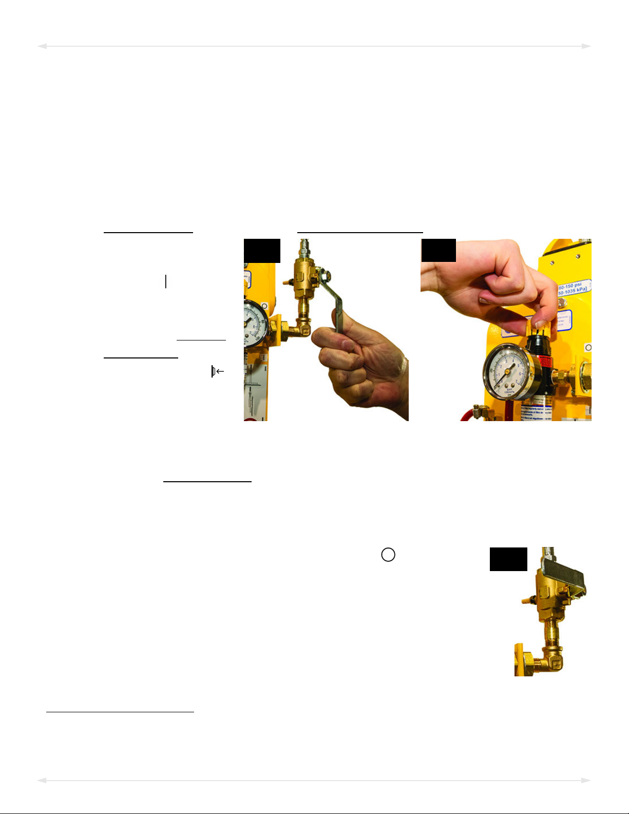
Generating Airflow............................................................................................................15
Positioning the Lifter on the Load.....................................................................................15
Sealing the Pads on the Load............................................................................................16
Reading the Vacuum Gauge..............................................................................................16
TOLIFT AND MOVE THE LOAD......................................................................17
Interpreting the Vacuum Gauge .......................................................................................17
Watching the Vacuum Gauge............................................................................................17
Controlling the Lifter and Load .........................................................................................18
In Case of a Power Failure.................................................................................................18
TORELEASE THE PADS FROM THE LOAD .........................................................19
About Stand-By Mode.......................................................................................................19
AFTER USING THE LIFTER.............................................................................20
Storing the Lifter ...............................................................................................................20
Transporting the Lifter ......................................................................................................20
INSPECTIONS AND TESTS......................................................................21
TABLE OF CONTENTS

FLEXR(L)-HV11AIR: #35036 Rev 5.1/4-212
INSPECTION SCHEDULE ................................................................................21
TESTING ...................................................................................................22
Lifter/Load Compatibility Test...........................................................................................22
Operational Tests ..............................................................................................................23
Vacuum Test......................................................................................................................23
Rated Load Test.................................................................................................................24
MAINTENANCE ....................................................................................25
VACUUM PAD MAINTENANCE.......................................................................25
Pad Inspection ..................................................................................................................25
Pad Cleaning .....................................................................................................................26
REPLACEMENT PARTS...........................................................................27
LIMITED WARRANTY ............................................................................28
TOOBTAIN REPAIRS OR WARRANTY SERVICE...................................................28
TABLE OF CONTENTS

Product
Description
Designed for use with hoisting equipment, FLEXR(L)-AIR lifters support loads using vacuum for lifting in
the flat orientation.
Model Number FLEXR4HV11AIR FLEXR6HV11AIR FLEXRL6HV11AIR
Pad Spread
(to outer edges) (w/4 pads — standard) (w/6 pads — standard) (w/6 pads — long)
Minimum 23" x 54¼"
[58 cm x 138 cm]
23" x 54¼"
[58 cm x 138 cm]
23" x 61"
[58 cm x 155 cm]
Maximum 41" x 70¼"
[104 cm x 178 cm]
41" x 70¼"
[104 cm x 178 cm]
41" x 105"
[104 cm x 267 cm]
Maximum Load
Capacity1
1...... The Maximum Load Capacity is rated at a vacuum of 16" Hg [-54 kPa] on clean, smooth, nonporous flat surfaces. Pad compound, load rigidity, strength,
surface conditions, overhang, angle, center of gravity and temperature can also affect the lifting capacity. A “qualified person” should evaluate the effective
lifting capacity for each use (see definition under “Rated Load Test”).
Per pad: 300 lbs [136.5 kg]
Total: 1200 [545 kg]
Per pad: 300 lbs [136.5 kg]
Total: 1500 [680 kg]
Per pad: 200 lbs [91 kg]
Total: 1200 [545 kg]
Lifter
Weight 100 lbs [46 kg] 125 lbs [57 kg] 145 lbs [66 kg]
Vacuum
Pads 10" [25 cm] nominal diameter, lipped (Model HV11), standard rubber2
2...... Available with other rubber compounds for special purposes (see www.wpg.com).
Power
Source Compressed air, 80-150 psi [550-1035 kPa] line pressure, 5 SCFM [142 liters/minute] @ 80 psi [550 kPa]
Product
Options
Available with Individual Pad Shutoffs.
Available with Spring-Shaft Pad Mounts.
See separate instructions about other options.
Operating
Elevation Up to 6,000' [1,828 m]
Operating
Temperatures 32° — 104° F [0° — 40° C]
Service
Life 20,000 lifting cycles, when used and maintained as intended3
3...... Vacuum pads, filter elements and other wear-out items are excluded.
ASME Standard
BTH-1 Design Category "B", Service Class "0" (see www.wpg.com for more information)
Troubleshooting
Guide4
4...... To view this guide, click the link at right. Additionally, you can search for your lifter's Model Number at www.wpg.com and select the “Troubleshooting” link
on the product page.
TST-016_GENERIC_LEAK_TEST_rev_2014-086
Rev 5.1/4-21 FLEXR(L)-HV11AIR: #350363
!!–CE–!! This symbol appears only when a CE Standard is different from other applicable standards. CE requirements are mandatory
in the European Union, but may be optional elsewhere.
SPECIFICATIONS

FLEXR(L)-HV11AIR: #35036 Rev 5.1/4-214
Note: A standard FLEXR6HV11AIR is shown.
SPECIFICATIONS

Rev 5.1/4-21 FLEXR(L)-HV11AIR: #350365
SAFETY
Wear personal protective
equipment that is appropriate for
the load material. Follow trade
association guidelines.
Do not remove or obscure safety
labels.
Do not make any modifications to
the lifter (see “LIMITED
WARRANTY”).
Use the lifter only in an approved
“OPERATING ENVIRONMENT”(see
“INTENDED USE”).
Do not use a lifter that is damaged,
malfunctioning, or missing parts.
Do not use a lifter if the sealing
edge of any vacuum pad is cut or
otherwise damaged.
Do not use a lifter to lift cracked or
broken glass.
Do not exceed the Maximum
Load Capacity or lift loads the
lifter is not designed for (see
“INTENDED USE”).
Do not use a lifter if the
Maximum Load Capacity or
any safety label appears to be
missing or obscured.
Make sure the contact surfaces of
the load and vacuum padsare clean
before attaching the lifter (see
“MAINTENANCE”).
Position the vacuum pads correctly
on the load before lifting (see
“OPERATION: Positioning the Lifter
on the Load”).
Do not lift a load if any vacuum
indicator shows inadequate
vacuum.
Keep unauthorized personnel away
from the lifter, to avoid injury in
case of an unintended load release.
Do not touch the vacuum release
controls during a lift.
Do not allow people to ride on the
lifter or the load.
Do not lift a load higher than
necessary or leave suspended loads
unattended.
Do not position a loaded or
unloaded lifter over people.
Before servicing a powered lifter,
place the power control in the
inactive position and, when
possible, disconnect the power source.

FLEXR(L)-HV11AIR: #35036 Rev 5.1/4-216
Features shown here are underlined on their first appearance in each section following.
1 LIFT POINT 2 CONTROL HANDLE 3 SLIDING PAD ARM
4 VACUUM PAD with MOVABLE MOUNT 5 VACUUMRESERVETANK 6 AIR FILTER (large)
7 PAD FRAME 8 AIR FILTER (small) 9 AIR PRESSURE REGULATOR/GAUGE
10 AIR SUPPLY VALVE 11 VACUUM GAUGE 12 VACUUM CONTROL VALVE
13 VACUUM PUMP (venturi)
Note: A standard FLEXR6HV11AIR is shown. Although some of the following photos do not show
this specific lifter, they all illustrate how this kind of lifter functions.
For information about specific parts, see “REPLACEMENT PARTS” and/or any separate
instructions for Product Options.
OPERATING FEATURES

Rev 5.1/4-21 FLEXR(L)-HV11AIR: #350367
1) Remove all shipping materials and save them with the shipping container for future use.
2)
Select a crane and/or hoist rated for the Maximum Load Capacity plus the
Lifter Weight.
Note: Any lifter use must comply with all statutory or regulatory standards for hoisting
equipment in your region.
3)
3A 3B 3C
Attach the hoisting
hook to the lift point
(figs. 3A-B).
Make sure
hook has
restraining latch
(circled).
Only use rigging rated for Maximum
Load Capacity plus Lifter Weight.
Note: Use rigging as needed to make sure
the hook does not interfere with the load
(fig. ).
4) Use the hoisting equipment to remove the lifter from the shipping container. Avoid
damaging the vacuum pads.
5)
5A
Remove the pad covers (fig. 5A) and save them for future use.
6)
6A 6B
Position the adjustable control
handles for optimal load
handling: Remove the
cotterless hitch pins (fig. 6A),
move the handles to suitable
positions where pin holes
align, and reinsert the pins
(fig. 6B).
ASSEMBLY

FLEXR(L)-HV11AIR: #35036 Rev 5.1/4-218
7) Connect the lifter to an appropriate compressed air supply (see Power Source under
“SPECIFICATIONS”):
Note: Qualified service personnel should install the female quick connector (supplied) on
the compressed air line.
Caution: Make sure the air line is routed so that it does not become tangled or damaged
during operation.
7.1) Connect the female quick connector to the male quick connector mounted on the
air supply valve. Then adjust the air pressure regulator to supply 80 psi [550 kPa]:1
7.2)
7A 7B
Place the air supply
valve in the “on”
position ( — fig. 7A).
7.3) With the lifter
suspended, place the
lever on the vacuum
control valve in the
“attach” position (
— see “Sealing the
Pads on the Load”).
7.4) Pull up the adjustment
collar on top of the regulator. Turn the collar clockwise to increase pressure or
counter-clockwise to decrease pressure (fig. 7B).
7.5) When the pressure gauge registers a minimum air pressure of 80 psi [550 kPa], push
down the collar to lock it in place.
7.6) Place the lever on the vacuum control valve in the center position (see “About
Stand-By Mode”).
7C
Note: Place the air supply valve in the “off” position ( — fig. 7C)
when the lifter is not in use; otherwise, the air compressor will cycle
frequently.
8) Perform tests as required under “TESTING”.
1..... Exceeding this pressure consumes more air and does not improve lifter performance.
ASSEMBLY

Rev 5.1/4-21 FLEXR(L)-HV11AIR: #350369
INTENDED USE
LOAD CHARACTERISTICS
Do NOT lift explosives, radioactive
substances or other hazardous materials.
Make sure the vacuum lifter is intended
to handle each load according to these
requirements:
• The load weight must not exceed the Maximum Load Capacity.
• The load must be a single piece of relatively nonporous material with a flat and
relatively smooth contact surface.1, 2To determine whether the load is too porous or
rough, perform a “Lifter/Load Compatibility Test”.
• The load's surface temperature must not exceed the Operating Temperatures.3
• The load's minimum length and width are determined by the current Pad Spread
(see “SPECIFICATIONS”).
• The load's maximum length and width are determined by its allowable overhang.4
Note: Standard vacuum pads can stain or deform load surfaces with light colors or soft coatings.
Test such surfaces for damaging effects before using the lifter on them.5
1..... Although concave vacuum pads can also attach to some curved loads, curvature can reduce lifting capacity. Contact WPG for more information.
2..... A “single piece” of material includes curtainwall assemblies, unitized glazing systems and similar construction units.
3..... Vacuum pads made from a heat-resistant rubber compound can enable you to lift loads with higher surface temperatures. Contact WPG or an
authorized dealer for more information.
4..... The allowable overhang is the amount of load material that can extend sideways beyond the vacuum pads without breaking or otherwise being
damaged. This depends on the load material, its thickness, and the angle of handling (if any). Since every material has different physical
properties, the allowable overhang must be evaluated separately for each load type. Contact WPG or an authorized dealer for more
information.
5..... Alternative rubber compounds are available for these purposes. Contact WPG or an authorized dealer for more information.

FLEXR(L)-HV11AIR: #35036 Rev 5.1/4-2110
OPERATING ENVIRONMENT
Make sure the vacuum lifter is intended for use in each work environment, given the following
restrictions:
•
Never use lifter
in dangerous
environments.
This lifter is not intended for any environment that is
dangerous to the operator or damaging to the lifter. Avoid
environments containing explosives, caustic chemicals and
other dangerous substances.
• The work environment is limited by the Operating Elevation and Operating
Temperatures.1, 2
• The lifter is not designed to be watertight. Moisture can result in
reduced lifting capacity.
Do not
use it in rain or other unsuitable conditions.
!!–CE–!! A secondary positive holding device is required to lift loads on construction sites.
DISPOSAL OF THE LIFTER
After the Service Life of the vacuum lifter has ended (see “SPECIFICATIONS”), dispose of it in
compliance with all local codes and applicable regulatory standards.
1..... Although lifter use may be possible at higher elevation, lifting capacity is reduced whenever the lifter is unable to attain vacuum in the green
range on the vacuum gauge. Contact WPG for more information.
2..... Special provisions may allow the lifter to operate outside the specified temperature range. Contact WPG for more information.
INTENDED USE

Rev 5.1/4-21 FLEXR(L)-HV11AIR: #3503611
OPERATION
BEFORE USING THE LIFTER
Determine whether the vacuum lifter is capable of each intended task (see “SPECIFICATIONS”
and “INTENDED USE”). Then complete the following preparations:
Taking Safety Precautions
•
Read all directions and safety rules before using
lifter.
Always wear appropriate personal protective
equipment.
Be trained in all industry
and regulatory standards
for lifter operation in your
region.
• Follow trade association
guidelines about precautions needed for each load material.
Performing Inspections and Tests
• Follow the “INSPECTION SCHEDULE”and “TESTING”.
•
Examine air filters regularly
and service when needed.
Examine the air filters and perform service
whenever their bowls contain liquid or other
contaminates or their elements appear dirty (see
“AIR FILTER MAINTENANCE” in SERVICE MANUAL).

FLEXR(L)-HV11AIR: #35036 Rev 5.1/4-2112
TOUSE THE OPTIONAL PAD SHUTOFFS
Each pad shutoff on the pad frame controls the vacuum line to the adjacent vacuum pad.
Activating or deactivating the airflow at specific pads enables the lifter to handle loads with
different weights and dimensions (see “SPECIFICATIONS”) or to avoid holes in the load surface.
Closing any pad shutoff
reduces lifting capacity.
To support the maximum load weight and larger load
dimensions, all pads must be activated; for smaller weights
and dimensions, some pads may be deactivated, provided
that the lifter still has sufficient capacity to support the
load (see “LOAD CHARACTERISTICS”).
1A 1B
To activate a pad,
place the valve
lever parallel with
the vacuum line
(ie, valve open —
fig. 1A).
To deactivate a
pad, place the
valve lever
perpendicular to
vacuum line (ie,
valve closed —
fig. 1B).
To calculate the lifting capacity when some pads are deactivated, consult the Per-Pad Load
Capacity and multiply by the number of pads currently activated. Always activate pads in
a symmetrical configuration and use as many pads as possible for each load being lifted, to
maximize lifting capacity and to minimize load overhang.
OPERATION

Rev 5.1/4-21 FLEXR(L)-HV11AIR: #3503613
TOADJUST PAD POSITIONS
Position vacuum hoses
as needed to prevent
damage to them during lifter
operation.
To reposition the vacuum pads on the pad frame for
handling various load dimensions (see “OPERATING
FEATURES”), move the sliding pad arms and movable pad
mounts as needed to provide optimal load support and to
minimize load overhang.
Note: The pads must be arranged symmetrically, to keep the load balanced.
Positioning Pad Arms
1)
1A
2A
Remove the cotterless hitch
pin from the mount for the
sliding pad arm on one end
of the pad frame (fig. 1A).
2) Slide the pad arm to a
suitable position where the
pin holes align (fig. 2A).
3) Reinsert the pin.
4) Repeat these steps to
position the opposite pad
arm at an equal distance
from the center of the lifter.
OPERATION

FLEXR(L)-HV11AIR: #35036 Rev 5.1/4-2114
Positioning Pad Mounts
1)
1A 2A
3A 4A
Remove the
cotterless
hitch pin
from one
movable pad
mount (fig.
1A).
2) Move the
pad mount
to a suitable
position
where the
pin holes
align (fig.
2A).
3) Reinsert the
pin (fig. 3A).
4) Reposition the other pad mount on the same arm at an equal distance from the main
beam of the pad frame (fig. 4A).
5) Repeat these steps for other pad mounts as needed.
TOADJUST THE CONTROL HANDLES
1)
1B 3B
Remove the
cotterless hitch pin
from one
adjustable control
handle (fig. 1B).
2) Move the handle to
a suitable position
where the pin holes align.
3) Reinsert the pin (fig. 3B).
4) Repeat these steps for other adjustable control handle, if desired.
OPERATION

Rev 5.1/4-21 FLEXR(L)-HV11AIR: #3503615
1A
Never place air supply valve in "off" position ( ) while
operating lifter.
Any interruption of airflow during lifter operation could result in an
unintentional load release and personal injury.
Positioning the Lifter on the Load
1) Make sure the contact surfaces of the load and vacuum pads are
clean (see “Pad Cleaning”).1
2)
2A
Center the pad frame on the
load (fig. 2A), to avoid
unexpected load movement
or release.2
Always center pad
frame on load.
Off-center loading could result in personal injury, as well as damage to the lifter or load.
3) Make sure all vacuum pads will fit on the load and will be loaded evenly.
Consult the Per-Pad
Load Capacity.
4) Place the vacuum pads in contact with the load surface.
1..... Since oil damages the rubber in standard pads, the load surface must be free of oil unless the lifter is equipped with optional oil-resistant pads
(see “REPLACEMENT PARTS”).
2..... The lifter is designed to handle the maximum load weight when its center of gravity is positioned within 2" [5 cm] of the pad frame’s center
point.
OPERATION
TOATTACH THE PADS TO ALOAD
Generating Airflow
Make sure the lever on the vacuum control valve is in the center position
(fig. 1A). Place the air supply valve in the “on” position ( — see
“ASSEMBLY”).

FLEXR(L)-HV11AIR: #35036 Rev 5.1/4-2116
Sealing the Pads on the Load
1)
1A
Place the lever on the vacuum control valve in the “attach”
position ( — fig. 1A).1
Keep valve lever in “attach” position throughout
lift.
Any interruption of airflow during lifter operation could result
in an unintentional load release and personal injury.
2) Make sure the vacuum pads seal completely against the load.2
Reading the Vacuum Gauge
A vacuum gauge shows the current vacuum level in positive inches of Hg and negative kPa:
•
1B 1C
Green range (>16" Hg [-54 kPa]):
Vacuum level is sufficient to lift the
maximum load weight (fig. 1B).
• Red range (<16" Hg [-54 kPa]):
Vacuum level is not sufficient to lift
the maximum load weight (fig. 1C).
If it takes more than 5 seconds for the
vacuum level to reach 5" Hg [-17 kPa], press
on any vacuum pad that has not yet sealed.
Once the pads have sealed, the lifter should be able to maintain sufficient vacuum for lifting,
except when used above the maximum Operating Elevation.3If it does not, perform the
“Vacuum Test”.
1..... Do not place the valve lever in the “attach” position until the vacuum pads are contacting the load.
2..... Although a vacuum pad may become distorted during shipping or storage, this condition should correct itself with continued use.
3..... If the lifter is used above the maximum Operating Elevation (see “SPECIFICATIONS”), it may not be able to maintain sufficient vacuum for lifting.
Contact WPG for more information.
OPERATION

Rev 5.1/4-21 FLEXR(L)-HV11AIR: #3503617
TOLIFT AND MOVE THE LOAD
Never attempt to lift load when
lifter is in horizontal orientation.
Interpreting the Vacuum Gauge
Never lift load unless vacuum gauge registers in the
green range, because premature lifting could result in
load release and personal injury.
Vacuum is sufficient
to lift the Maximum
Load Capacity whenever the
vacuum gauge registers in
the green range.
Watching the Vacuum Gauge
1B
Watch the vacuum gauge (fig. 1B) throughout the entire lift.
Make sure the vacuum gauge remains
completely visible.
The vacuum pump runs continuously to maintain sufficient vacuum for
lifting the maximum load weight.
However, if the vacuum gauge shows a level less than 16" Hg [-54 kPa]:
1)
Stay clear of any suspended load
while gauge warns of low vacuum.
Keep everyone away from a suspended
load until it can be safely lowered to a
stable support.
2) Stop using the lifter until the cause of the vacuum loss can be identified: Conduct the
“Pad Inspection” and perform the “Vacuum Test”.
3) Correct any faults before resuming normal operation of the lifter.
OPERATION

FLEXR(L)-HV11AIR: #35036 Rev 5.1/4-2118
Controlling the Lifter and Load
1A
When the lifter is ready, use the hoisting equipment to raise
the lifter and load as needed.
Use a control handle (circled in fig. 1A) to keep the lifter and
load in the required position.
Once there is enough clearance, you may move the load as
required.
Never allow any pad shutoff to be opened or
closed while lifting, because this could result in a
load release and personal injury.
In Case of a Power Failure
A vacuum reserve tank helps maintain vacuum temporarily in the event of a power failure.
Although the lifter is designed to support the load for at least 5 minutes without power,this
depends on many factors, including the “LOAD CHARACTERISTICS”and the condition of the
vacuum pads (see “VACUUM PAD MAINTENANCE”).
Stay clear of any suspended
load during power failure.
If a power failure occurs, keep everyone away from a
suspended load until it can be safely lowered to a stable
support. Correct any faults before resuming normal
operation of the lifter.
OPERATION
Other manuals for FLEXR Series
3
This manual suits for next models
4
Table of contents
Other WPG Industrial Equipment manuals

WPG
WPG MRPT89AC User manual

WPG
WPG MRTA4LP6FACS User manual

WPG
WPG MRTALP4625DC3 User manual

WPG
WPG FLEXR Series User manual

WPG
WPG TL3AM User manual

WPG
WPG MRTALPCH611DC3 User manual

WPG
WPG QUADRA-TILT MRTA811LDC3 User manual

WPG
WPG LJ6VH User manual

WPG
WPG MRT4 Series User manual

WPG
WPG N Series User manual
Popular Industrial Equipment manuals by other brands

Kaco
Kaco 87.0-165 TL3 manual

HEIDENHAIN
HEIDENHAIN ECI 1319 EnDat22 Mounting instructions

Nordmann Engineering
Nordmann Engineering MultiPipe Installation and operating instructions

Graziadio & C.
Graziadio & C. K Series Assembly instructions

ROVEMA
ROVEMA CMK Operator's manual

Siemens
Siemens PolyBlend PB200-2 manual