INW AquiStar TempHion User manual

19026 72nd Avenue South
Kent, WA 98032 USA
253.872.0284
FAX 253.872.0285 / [email protected]
INW, A Division of Seametrics
INW TempHionTM
Smart Sensor (ph, ISE, Redox/ORP)
©1997 - 2016 Seametrics. All rights reserved. Instrumentation Northwest and INW are trademarks of Seametrics.
Doc# 9B0810r12.2 1/6/2016 / PN 6D279-NI
INSTRUCTION MANUAL

INW - TempHion Instruction Manual 1
Table of Contents
Introduction ......................................................................................................................3
What is the TempHionTM Smart Sensor? ...................................................................3
Initial Inspection and Handling .................................................................................3
Do’s and Don’ts.........................................................................................................3
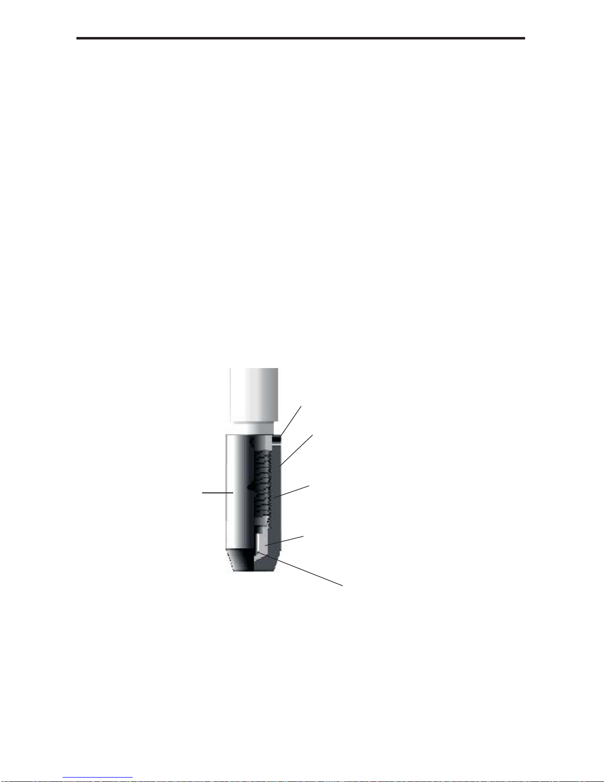
TempHionTM Reference Electrode.............................................................................4
Battery Life Note.......................................................................................................5
General Precautions...................................................................................................5
Installation and Operation.................................................................................................5
Connecting External Power.......................................................................................6
Connecting the TempHionTM to a Computer..............................................................6
Installing the Aqua4Plus or Aqua4Plus Lite Software ..............................................6
Calibration .................................................................................................................6
Field Deployment ......................................................................................................7
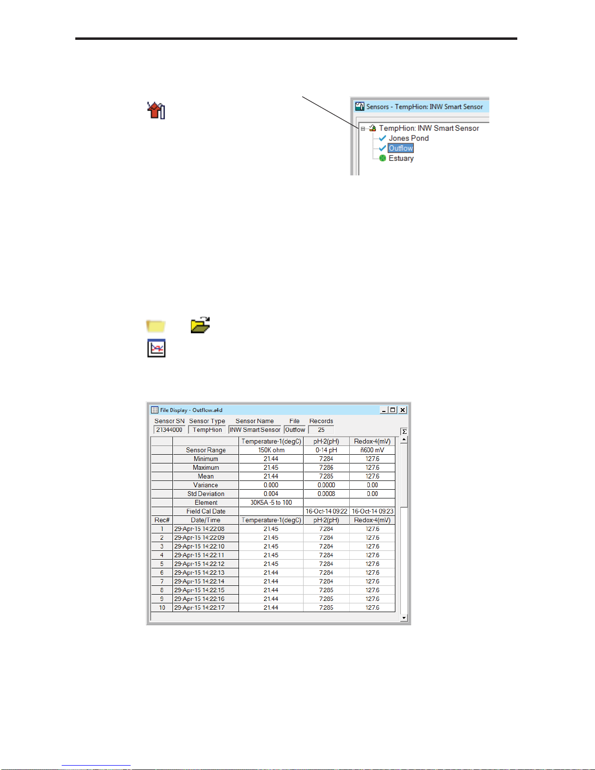
Collecting Data..........................................................................................................8
Maintenance....................................................................................................................11
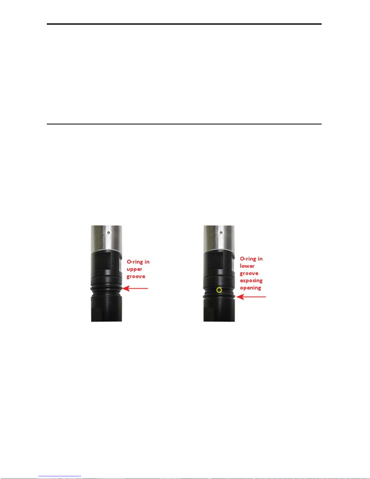
Care and Filling of Reference Solution Reservoir...................................................11
Storing Sensor..........................................................................................................13
Changing Batteries...................................................................................................13
Appendix A: Technical Specifications............................................................................14
Wiring Information..................................................................................................14
Dimensions and Specifications................................................................................15
Appendix B: Settings and Calibration ............................................................................17
Calibration Overview...............................................................................................17
Settings and Calibration Window and Calculator....................................................18
Temperature Channel Calibration............................................................................18
pH Channel Calibration...........................................................................................18
ISE Channel Calibration..........................................................................................20
Redox (ORP) Channel Calibration..........................................................................23
Appendix B1: pH Field Calibration Temperature Chart.................................................24
Appendix B2: M & I Range for pH Calibration.............................................................24
Appendix C: Elements, Reference Solutions, and Related Settings...............................25
Appendix D: How to Store and Recondition..................................................................26
Storage.....................................................................................................................26
Reconditioning ........................................................................................................26
Appendix E: Alternate Connection Options ...................................................................27
Connecting via RS232 Serial Port...........................................................................27
Connecting with a USB/Serial Adapter...................................................................27
Appendix F: Reading the TempHionTM via Direct Read................................................29
Setting Units for Direct Read ..................................................................................29
Reading Via Modbus®RTU.....................................................................................30
Reading Via SDI-12.................................................................................................32
Appendix G: Battery Changing Details..........................................................................34
Reordering Information ..................................................................................................38
Limited Warranty/Disclaimer - AquiStar®TempHionTM Smart Sensor..........................39

2 INW - TempHion Instruction Manual
Information in this document is subject to change without notice and does not
represent a commitment on the part of the manufacturer. No part of this manual may
be reproduced or transmitted in any form or by any means, electronic or mechanical,
including photocopying and recording, for any purpose without the express written
permission of the manufacturer.
©1997 - 2016 Seametrics. All rights reserved.
Registered trademarks and trademarks belong to their respective owners.

INW - TempHion Instruction Manual 3
Introduction
What is the TempHionTM Smart Sensor?
The AquiStar®TempHionTM Smart Sensor is a submersible water quality sensor and
datalogger capable of measuring pH, specific ions, redox (ORP), and temperature. Each
unit comes with a thermistor based temperature element plus a combination of pH, ISE,
or redox (ORP) elements. (Contact INW for available combinations.)
The TempHionTM Smart Sensor is powered internally with twoAA1.5V batteries or
with an auxiliary 12VDC power supply for data intensive applications. The unit is
programmed using a Windows®based computer and INW’s easy-to-use Aqua4Plus or
Aqua4Plus Lite software. Once programmed, the unit will measure and collect data on
a variety of time intervals.
Several TempHions, or a combination of TempHions and other INW Smart Sensors, can
be networked together and controlled from one location, either directly from a single
computer or via INW’s Wireless Data Collection System.
The internal processor in the TempHionTM Smart Sensor allows for easy calibration,
using the calibration utilities in Aqua4Plus/Aqua4Plus Lite. Once calibrated, this
calibration data is stored in non-volatile memory within the Smart Sensor. When data is
collected, this calibration information is applied to the data, resulting in highly accurate
readings at a wide range of temperatures.
Initial Inspection and Handling
Upon receipt of your smart sensor, inspect the shipping package for damage. After
opening the carton, look for concealed damage, such as a cut cable. If damage is found,
immediately file a claim with the carrier. Check the label attached to the cable at the
connector end for the proper cable length.
Do’s and Don’ts
Do handle the device with care.
Do refer to Appendix D for storage information.
Don’t install the device so that the connector end is submerged.
Don’t support the device with the connector or with the connectors of an extension
cable. Use a strain relief device to take the tension off the connectors.
Don’t allow the device to free-fall down a well as impact damage can occur.
Don’t bang or drop the device on hard objects.

4 INW - TempHion Instruction Manual
TempHionTM Reference Electrode
TempHion’s patented reference electrode is the key to TempHion’s superior downhole/
high pressure performance. TempHion uses a long capillary pathway, initially filled
with reference electrode filling solution, to separate the reference electrode chamber
from the solution being analyzed. In addition, TempHion’s reference electrode is
filled without any air (which is compressible). With this construction, the principle
mechanism that will eventually allow test solution to enter the reference chamber and
contaminate the reference electrode filling solution is diffusion – an exceedingly slow
mechanism. Further, while the capillary pathway is narrow by garden hose standards,
its open cross-section is huge compared to the microscopic openings in a conventional
porous ceramic fluid/fluid junction. It is therefore much less susceptible to fouling.
Fluid expansion and contraction caused by temperature variations can augment the
effects of diffusion. Nevertheless, TempHion’s proven stability under actual field
conditions is measured in weeks or months, rather than hours or days!
The figure below illustrates the construction of the TempHionTM reference electrode.
Please note that the capillary pathway between the reference and test solutions is
established using a modified screw thread. This means that the capillary can be easily
opened up for cleaning, refilling, or other maintenance.
TempHions with standard pH elements, ISE elements, and ORP elements come with
the TempHion Reference Electrode, as described above. The TempHion is also sold
with a wastewater pH element that has a built in reference and so does not use a filling
solution.
Reference Electrode Assembly: The modified thread provides
a continuous liquid path between the solution in which the
instrument is immersed and the reference element.
Reference
Electrode
Assembly
Liquid Junction Port
Outer Reference Housing
Capillary Flow path
(Modified Thread)
Reference Electrode
Filling Solution
Reservoir
Reference Element

INW - TempHion Instruction Manual 5
Battery Life Note
The TempHion sensors are shipped from the factory with fresh internal AA batteries.
Battery life will depend on battery brand, battery age, temperature of the environment,
usage schedule, and other factors.
General Precautions
The rest of this manual includes step-by-step instructions for setting up the
TempHionTM, calibrating it, and using it in the field. When reading and following
the instructions in these sections, keep these very important considerations in mind:
• Do not handle the surfaces of the sensing electrodes. Oils from fingers can
“blind” the reactive surface. Rough handling can scratch the reactive surface.
• Avoid long-term exposure of silver-based sensing electrodes to bright sunlight.
• Use calibration standards that are accurately prepared. Discard standards after
use. Do not return the used standards to the bottles of “fresh” solution.
• When TempHion’s reference electrode contains filling solution, the o-ring at the
top of the reference assembly must be in the upper position. (See further details
under Field Deployment later in this manual.)
• For any step-change in temperature (e.g., where calibration standards are at a
different temperature than water to be tested) allow the instrument to come to
complete thermal equilibrium before making measurements. Up to 30 minutes
may be required.
Installation and Operation

6 INW - TempHion Instruction Manual
Connecting External Power
The TempHionTM comes with twoAAinternal batteries. If auxiliary power is desired,
you can use a 6 - 13 VDC supply that can provide 15 mA. Connect to Vaux++ (white)
and Ground (blue) or contact INW for auxiliary power connectors.
Connecting the TempHionTM to a Computer
In its cabled configuration, the sensorcable is terminated with a weather-resistant
connector. In its cableless configuration, the sensor is terminated with a weather-
resistant connector inside a screw-cap. Connect the weather-resistant connector to
your computer’s USB port as shown below. (For alternate connection options, see
Appendix E.)
Connect the TempHionTM to your PC using a USB to RS485 adapter.
(See Appendix E for alternate connection options.)
Installing the Aqua4Plus or Aqua4Plus Lite Software
The TempHionTM comes with theAqua4Plus/Aqua4Plus Lite host software to be
installed on your PC or laptop. Use this software to calibrate the sensor, to program the
datalogger, to retrieve data from the logger, to view collected data, and to export data to
external files for use with spreadsheets or databases. Refer to the software manuals for
details on installing and using the program.
Calibration
The TempHion has one temperature channel and four millivolt channels. The millivolt
channels can be configured to measure pH, redox, or various selected ions. Before
leaving the factory, your sensor has been configured specifically for you. All unneeded
channels have been disabled, and the active channels have been pre-configured.
Disabled channels will not display in Aqua4Plus/Aqua4Plus Lite. (Note: Some older
TempHions may have more channels. If yours has more channels, refer to the docu-
mentation that came with the unit or contact INW for more information.)
PC or Laptop
Computer
USB Port
USB to RS485
Adapter
Sensor
Cableless
Configuration
Screw-
Sensor
cap

INW - TempHion Instruction Manual 7
All active channels can be calibrated in the field. Temperature channels rarely need
calibrating, however the pH, ISE, and Redox (ORP) channels should be calibrated
before first use and periodically thereafter.
Environmental conditions of turbulence and temperature swings, as well as local bio-
fouling or mineral deposition, can vary considerably from site to site. Therefore, where
the sensor is to be used for long-term monitoring, it is recommended that the calibration
be initially checked frequently until a performance history is established.
See Appendix B for detailed calibration instructions.
Field Deployment
The black reference reservoir at the lower end of the TempHionTM Smart Sensor is
shipped filled with INW reference solution. (If your reference reservoir is not filled,
see the Maintenance section in this manual.) The black reference assembly has two
grooves. The upper groove contains a small hole that forms the liquid junction port.
During shipping and storage, an o-ring is located in the upper groove, preventing
reference solution leakage and contamination. Be sure to move the o-ring to the lower
groove before deploying, thus exposing the liquid junction port. If the o-ring continues
to cover the opening, readings will not be representative or accurate.
Be sure to move the o-ring to the lower groove before
deploying, thus exposing the liquid junction port.
(If you have the wastewater pH element, disregard the previous paragraph.)
Lower the sensor to the desired depth. Fasten the cable to the well head using tie
wraps or a weather proof strain-relief system. (Note that for shallow installations the
liquid in which the sensor is submerged must, at all times, reach high enough to cover
the sensing element cutout.)
Be sure the supplied cap is securely placed on the weather-resistant connector at the
top of the cable. Do not install such that the connector might become submerged with
changing weather conditions. The connector can withstand incidental splashing but is
not designed to be submerged.

8 INW - TempHion Instruction Manual
Collecting Data
Following is a brief overview on using Aqua4Plus/Aqua4Plus Lite to collect data.
Please refer to the software manuals for further details.
Real Time Monitor
The Real Time Monitor gives a snapshot
of the current readings on the sensor.
Setting up Data Recording
Click the tool button. A Logging Schedule Window will open. Refer to the software
manuals for details in describing your schedule. Click the Start button to send the
schedule to the sensor and begin recording.
Using the Logging Schedule Window, describe
the test steps for your particular test.
Click Single to get a single
reading.
Click Start to get a reading
once a second for 60 seconds.
Click Stop to stop the reading.
Note: These are snapshot
readings and are not recorded
on the sensor.

INW - TempHion Instruction Manual 9
Retrieving Data from the Sensor/Datalogger
• Click on the file you want to retrieve.
• Click the tool button.
• Select a file location.
• Click Save.
• Click Start.
Select the data file you are
ready to retrieve.
Viewing Data
• Click the or tool button to view data as a table.
• Click the tool button to view data as a graph.
• Navigate to the desired file, then click the Open button.
The File Display Window displays
your data in a tabular format.

10 INW - TempHion Instruction Manual
The Graph Window displays your
data on an X Y coordinate graph.
Exporting Data to .csv or .xls Files
• Click the or tool button to view data as a table.
• Click on the tool button.
• Select a file location and enter a name for the file.
• Select a file type.
• Click Save.
A Word About Units
Readings from the TempHionTM Smart Sensor can be displayed in various units. Select
the units you want from the Options | Display Units menu or from the Configure Menu |
Program Configuration | Set Computer Display Units.
pH: pH or mV
ISE: ppm or mV
Redox: Eh or mV
Temperature: Degrees Celsius, Fahrenheit, Kelvin, or ohms
When using pH, ppm, or Eh units, all readings are automatically compensated for
temperature and all field calibration factors are applied. When using millivolts or ohms,
only the actual millivolt or resistance values are displayed, no adjustments are made.

INW - TempHion Instruction Manual 11
Maintenance
Care and Filling of Reference Solution Reservoir
(Note: See Appendix C for correct filling solution for your unit. Disregard if using the
wastewater pH element.)
The TempHion’s patented reference electrode is key to the TempHion’s superior
performance. The TempHion uses a long capillary pathway, filled with reference
solution, to separate the reference electrode from the solution being analyzed. Proper
care and filling of this reference solution reservoir is essential to accurate functioning
of the sensor.
Your TempHion is normally shipped from the factory already filled with reference
solution. However, from time to time you will need to replace the reference solution. If
you notice you are getting erratic readings, this is an indication that the filling solution
may need to be replaced. We also recommend replacing the filling solution when doing
periodic calibrations.
The TempHion is normally shipped with a bottle of INW Reference Solution. If you
will be using a different solution, contact INW for any adjustments that may be needed.
Emptying and Cleaning the Reservoir
Rinse the reference electrode and the inside
of the cap with distilled or de-ionized water.
Unscrew the reservoir cap. Do not touch or scratch the sensing buttons or the
reference electrode!
Empty any remaining filling solution from the cap.
Thoroughly rinse the reference electrode and the inside of the cap with distilled
or de-ionized water.
There may be some crystallized residue inside the cap, on the electrode screw
path, or on the electrode itself. If rinsing does not clear this away, then gently
use a cotton swab or a soft toothbrush to remove the residue.
Rinse the electrode assembly and cap thoroughly again after cleaning with the
swab or brush.
Gently, pat dry with a clean paper towel.

12 INW - TempHion Instruction Manual
Filling the Reservoir
Once the reservoir has been emptied and cleaned, you are ready to fill the reservoir
with reference solution.
Rinse the reference electrode assembly and the inside of the cap with a small
amount of the reference solution.
Empty any remaining solution from the cap.
Fill cap about half full with reference solution.
Holding sensor vertically, replace reservoir cap. Some solution should spill from
the top as you screw the cap on. This assures that no air bubbles are trapped in-
side. If any air bubbles are trapped, a proper electrical connection cannot be
made and the sensor may read erratically!
Once filled, be sure the o-ring is in the upper groove to prevent reference solution
leakage and contamination. Before deploying be sure to move the o-ring to the
lower groove to expose the liquid junction port.
Be sure to move the o-ring to the lower groove before
deploying, thus exposing the liquid junction port.
Excess filling solution
spills over, forcing out
any air bubbles.
CAUTION: Filling solutions are not considered hazardous, but they
can be irritating to the skin. Protective gloves are advised. Rinse
hands or gloves with fresh water.

INW - TempHion Instruction Manual 13
Storing Sensor
Refer to Appendix D for information on storage.
Changing Batteries
Battery Type: Two 1.5V AA batteries.
Because changing the batteries involves opening the water-tight seal, this must be
done in a clean, dry environment to avoid contamination or moisture damage to
the circuitry.
Refer to Appendix G for details on changing batteries.
PREVENT BATTERY LEAKAGE!
Under some circumstances the internal batteries can leak, causing damage
to the sensor. To prevent leakage, the following is recommended. (Does not
apply to lithium batteries.)
• Change the batteries at least every 18 months.
• If the sensor will not be deployed for 3 months or more, remove the
batteries.

14 INW - TempHion Instruction Manual
Appendix A: Technical Specifications
Wiring Information
Cable Type: 9-conductor, shielded
Shield = Ground
White = Vaux (6 to 13 VDC)
Brown = SDI-12
Orange = Vbat+ (1.8 to 3.3 VDC)
Blue = Ground
Yellow = Comm D+
Purple = Comm D-
For SDI-12 —
with 5-pin connector
For SDI-12 —
without connector
White
Purple
Yellow
Brown
Blue
Shield
12 VDC+ (Vaux)
Modbus D- (Not used)
Modbus D+ (Not used)
SDI-12 Signal
12 VDC – (Gnd)
1
2
3
4
5
5-Pin
Connector
White
Purple
Yellow
Brown
Blue
Shield
(may be green)
12 VDC+ (Vaux)
Modbus D- (Not used)
Modbus D+ (Not used)
SDI-12 Signal
12 VDC – (Gnd)
Earth ground
For Modbus®—
with 5-pin connector
White
Purple
Yellow
Brown
Blue
Shield
12 VDC+ (Vaux)
Modbus D-
Modbus D+
SDI-12 (Not used)
Ground
1
2
3
4
5
5-Pin
Connector

INW - TempHion Instruction Manual 15
Dimensions and Specifications
SENSOR
Length
w/batteries 17.96” (45.6 cm)
w/o batteries 14.16” (36.0 cm)
Cableless 0.25” (0.6 cm) shorter
Diameter 0.75” (1.9 cm)
Weight 0.85 lb (0.4 kg)
Body Materials Acetal & 316 stainless steel or titanium
Wire Seal Materials Flouropolymer and PTFE
Submersible Cable Polyurethane, polyethylene, FEP or ETFE
Cable Weight 4 lbs/100 ft (1.8 kg/30 m)
Communication RS485 Modbus®
Available Channels Temperature, pH and ORP
Temperature, ISE
Operating Temperature Range 0° C to 55° C
Storage Temperature Range1-20° C to 80° C
Reference
Electrode Ag/AgCl solid-state electrode
Junction Patented capillary liquid junction
Electrolyte TempHionTM reference solution
Maximum Depth pH/ORP: 700 ft. (210 m), 300psi
ISE: 230 ft. (70 m), 100 psi
LOGGING
Memory 4MB - 400,000 records
Logging Rate 2x/sec
File Formats .xls / .csv / .a4d
Baud Rates 9600, 19,200, 38,400
POWER
Internal Battery 2x1.5V AAAlkaline2
Auxiliary Power 12 VDC – Nominal
6V-15VDC – Range
1Storage without batteries
2Lithium available upon request

16 INW - TempHion Instruction Manual
TEMPERATURE
Element Type 30K ohm thermistor
Element Material Epoxy bead/external housing
Accuracy ± 0.2° C
Resolution 0.01° C
Units Celsius, Fahrenheit, Kelvin
ION SPECIFIC ELECTRODE
Chloride/Bromide
Measurement Principle Ion electrode method
Probe Material Ag/AgCl solid-state electrode
Range 0-10,000 ppm
Typical Accuracy ± 5.0% of measured value
Resolution 0.1 ppm
Thermal Compensation Isopotential point characterization
Calibration 1-2 point method w/ ionic strength adjustment
Reference Solution (Chloride) ION-Plus B
Reference Solution (Bromide) Potassium Nitrate - (KNO3)
pH/REDOX
Sensor Type/Material
pH Glass combination electrode
Redox Platinum ring
Ranges
pH 0-14 pH units / -538mV to 260mV
Redox ± 1200mV
Units
pH pH, mV
Redox Eh (mVH), mV
Typical Accuracy
pH ± 0.2 pH units
Redox 0.1 Eh (mVH)
Resolution
pH 0.01 pH units
Redox 0.01 Eh (mVH)
Calibration
pH 1 and 2 point w/ pH buffers (4, 7, or 10)
Redox 1 point
Reference Solution Potassium Nitrate - (KNO3)

INW - TempHion Instruction Manual 17
Appendix B: Settings and Calibration
Calibration Overview
The TempHion should be calibrated before first use and periodically thereafter. It
should also be calibrated if moving to a different sampling environment where readings
will be significantly different than the current environment.
Environmental conditions of turbulence and temperature swings, as well as local
likelihood for bio-fouling or mineral deposition, can vary considerably from site to site.
Therefore, where the sensor is to be used for long-term monitoring, it is recommended
that the calibration be initially checked frequently until a performance history is
established.
Aqua4Plus/Aqua4Plus Lite provides an easy-to-use calibration calculator for
performing one- or two-point in-field calibrations. Two-point calibrations are more
accurate and should be used whenever possible. A Calibration Kit is available from
INW, which includes a beaker, pipette, measuring beaker, and stand.
IMPORTANT CALIBRATION NOTES!
• Filling Solution Reservoir (Does not apply to wastewater pH element)
• In order for the TempHion Smart Sensor to calibrate and function correctly,
the filling solution reservoir must be properly filled with reference solution.
For details, see earlier in this manual.
• Be sure the o-ring on the black reference housing has been moved to the
lower groove, exposing the liquid junction port.
• The sensor and all calibration buffers and solutions should be at the same
temperature before and during calibration.
• Refer to Appendix D for reconditioning times prior to calibration.
• Calibration can only be done when there is no data stored on the sensor.
Retrieve any data you want and then erase the data before continuing.
IMPORTANT RECONDITIONING NOTES!
• If your reference electrode has been stored dry or in KCl solution, you
should let it sit at least a half hour after filling with reference solution
before using or calibrating.
• If your pH sensor has been stored with the bulb dry, you should soak it
in your first pH buffer for about four hours to recondition the bulb before
calibrating. This applies to the wastewater element, also, if it has been
stored dry.
• If your chloride or bromide sensor has been stored with the element dry,
you should soak it in your first calibration solution for at least a half hour
before using or calibrating.
See Appendix D for more information on storage and reconditioning.

18 INW - TempHion Instruction Manual
Settings and Calibration Window and Calculator
Field calibration is performed on each channel separately. To calibrate a specific
channel, select Settings and Calibration from the Configure Menu in Aqua4Plus
(click the Settings button in Aqua4Plus Light), and then click on the channel to be
calibrated. Follow directions below for each specific channel type.
Use the calibration calculator to perform
one- and two-point calibrations.
Temperature Channel Calibration
The temperature channel rarely needs adjustment. If you think your temperature
channel needs calibrating, contact your service representative.
pH Channel Calibration
Preparing
• INW recommends pH buffers of 4, 7, and 10 for calibration. For a one-point
calibration, select the buffer closest to the expected values in your samples.
For a two-point calibration, select the two buffers that most closely bracket the
expected values in your samples.
• Before calibrating, check the chart in Appendix B2 for the range of M and I
values you can expect to obtain during calibration.
IMPORTANT !
The pH of any buffer varies slightly with temperature change. For this reason,
it is important that you determine the current pH value of the buffer you are
using. Refer to Appendix B1 for a pH Buffer / Temperature chart. From this
chart, determine the pH value at your current buffer temperature and use this
value as the “Ref pH” value in the calibration instructions below. For example,
if you are using a pH buffer of 7 and your buffer temperature is 20 degrees C,
then you would enter 7.02 in the Ref pH box.

INW - TempHion Instruction Manual 19
One-Point Calibration
— First Calibration Point —
• Prepare the buffer.
• Rinse sensor first with distilled water and then with small amount of the buffer.
• Place sensor in buffer. (Buffer must be deep enough to cover the sensing bulb in
the cutout on the sensor.)
• Allow time for sensor to stabilize.
• In the Ref pH box for the first point, enter the temperature adjusted reference pH
as noted in the preparation section above.
• Click first Measure button.
• When readings have stabilized to your satisfaction, click the OK button in the
pop-up box.
— Applying Calibration Values —
• Observe the Ivalue in the right hand section of the calculator. This should be
between the I values shown in the chart in Appendix B2.
• Click the Apply button to apply calibration values.
• The reference value, the computed I, and the sample temperature will be
transferred to the calibration fields.
• Click OK to save the values to the sensor.
— Verifying Calibration Values —
• Using the Real Time Monitor, take a few readings while the sensor is still in
the buffer. Be sure units are set to pH. Readings should be very close to your
selected buffer.
Two-Point Calibration
— First Calibration Point —
• Prepare first buffer.
• Rinse sensor first with distilled water and then with small amount of first buffer.
• Place sensor in buffer. (Buffer must be deep enough to cover the sensing bulb in
the cutout on the sensor.)
• Allow time for sensor to stabilize.
• In the Ref pH box for the first point, enter the temperature adjusted reference pH
as noted in the preparation section above.
• Click first Measure button.
• When readings have stabilized to your satisfaction, click the OK button in the
pop-up box.
— Second Calibration Point —
• Prepare the second buffer.
• Rinse sensor first with distilled water and then with small amount of second
buffer.
• Place sensor in second buffer. (Buffer must be deep enough to cover the sensing
bulb in the cutout on the sensor.)
Other manuals for AquiStar TempHion
1
Table of contents
Other INW Accessories manuals