INW AquiStar TempHion User manual

TM
AquiStar
TT
TT
TempHionempHion
empHionempHion
empHion
Smart Sensor
(pH, ISE, Redox)
INSTRUCTION
MANUAL
®
Instrumentation
Northwest, Inc.
Protecting our water resources since 1982

1
Table of Contents
Introduction ..................................................................................................................... 3
What is the TempHionTM Smart Sensor? ................................................................... 3
Initial Inspection and Handling ................................................................................ 3
Do’s and Don’ts ....................................................................................................... 3
TempHionTM Reference Electrode ............................................................................. 4
General Precautions .................................................................................................. 5
Installation and Operation ............................................................................................... 5
Instrument Setup ...................................................................................................... 5
Connecting External Power ....................................................................................... 6
Connecting the TempHionTM to a Computer ............................................................. 6
Installing the Aqua4Plus Software ............................................................................ 7
Calibration ................................................................................................................ 7
Field Deployment ...................................................................................................... 7
Collecting Data ......................................................................................................... 8
Appendix A: Field Calibration ......................................................................................... 11
Calibration Overview ............................................................................................... 11
Field Calibration for Thermistor Channels ............................................................... 13
Field Calibration for pH Channels ............................................................................ 14
Field Calibration for ISE (Selective Ion) Channels ................................................... 15
Field Calibration for Redox Channels ....................................................................... 17
Appendix B: Technical Specifications ............................................................................. 18
Wiring Information ................................................................................................... 18
Operating Specifications .......................................................................................... 18
Mechanical Specifications ....................................................................................... 19
Power Supply ........................................................................................................... 19
Appendix C: Changing Batteries ..................................................................................... 20
Appendix D: Temperature Correction Factors ................................................................. 21
Appendix E: Using USB-to-Serial Cables ........................................................................ 22
Reordering Information ................................................................................................... 23
Limited Warranty/Disclaimer - AquiStar®TempHionTM Smart Sensor ............................. 24

2
Information in this document is subject to change without notice and does not represent
a commitment on the part of the manufacturer. No part of this manual may be
reproduced or transmitted in any form or by any means, electronic or mechanical,
including photocopying and recording, for any purpose without the express written
permission of the manufacturer.
©1997 - 2006 Instrumentation Northwest, Inc.
Registered trademarks and trademarks belong to their respective owners.

3
Introduction
What is the TempHionTM Smart Sensor?
The AquiStar®TempHionTM Smart Sensor is a submersible water quality sensor and
datalogger capable of measuring pH, specific ions, redox, and temperature. Each unit
comes with one or two thermistor based temperature elements plus up to four pH, ISE, or
redox elements. (Contact INW for available combinations.) The TempHionTM Smart
Sensor records, operates on low power, and comes with easy-to-use software with
powerful features.
The TempHionTM Smart Sensor is powered internally with two AA alkaline batteries or
with an auxiliary power supply for data intensive applications. The unit is programmed
using a laptop or desktop Windows®based computer via its RS485/RS232 adaptor and
INW’s Aqua4Plus software. Once programmed, the unit will measure and collect data on
a variety of time intervals.
Several TempHions, or a combination of TempHions and other INW Smart Sensors, can
be networked together and controlled from one location, either directly from a single
computer or via a WaveData®Wireless Data Collection System.
The internal processor in the TempHionTM Smart Sensor allows for easy calibration,
using the calibration utilities in Aqua4Plus. Once calibrated, this calibration data is
stored in non-volatile memory within the Smart Sensor. When data is collected, this
calibration information is applied to the data, resulting in highly accurate readings at a
wide range of temperatures.
Initial Inspection and Handling
Upon receipt of your smart sensor, inspect the shipping package for damage. After
opening the carton, look for concealed damage, such as a cut cable. If damage is found,
immediately file a claim with the carrier. Check the label attached to the cable at the
connector end for the proper cable length.
Do’s and Don’ts
Do handle the device with care.
Do store in water or calibration solution and keep vertical once filled with reference
solution.
Don’t install the device so that the connector end is submerged.
Don’t support the device with the connector or with the connectors of an extension
cable. Use a strain relief device to take the tension off the connectors.
Don’t allow the device to free-fall down a well as impact damage can occur.
Don’t bang or drop the device on hard objects.

4
TempHionTM Reference Electrode
TempHion’s patented reference electrode is the key to TempHion’s superior downhole/
high pressure performance. TempHion uses a long capillary pathway, initially filled
with reference electrode filling solution, to separate the reference electrode chamber
from the solution being analyzed. In addition, TempHion’s reference electrode is filled
without any air (which is compressible). With this construction, the principle mecha-
nism that will eventually allow test solution to enter the reference chamber and contami-
nate the reference electrode filling solution is diffusion - an exceedingly slow mecha-
nism. Further, while the capillary pathway is narrow by garden hose standards, its open
cross-section is huge compared to the microscopic openings in a conventional porous
ceramic fluid/fluid junction. It is therefore much less susceptible to fouling. Fluid
expansion and contraction caused by temperature variations can augment the effects of
diffusion. Nevertheless, TempHion’s proven stability under actual field conditions is
measured in weeks or months, rather than hours or days!
Figure 1 illustrates the construction of the TempHionTM reference electrode. Please note
that the capillary pathway between the reference and test solutions is established using
a modified screw thread. This means that the capillary can be easily opened up for
cleaning, refilling, or other maintenance.
Reference
Electrode
Assembly
Liquid Junction Port
Outer Reference Housing
Capillary Flowpath
(Modified Thread)
Reference Electrode
Filling Solution
Reservoir
Reference Element
Figure 1: Reference Electrode Assembly:
The modified thread provides a continuous liquid path between the
solution in which the instrument is immersed and the reference element.

5
General Precautions
The rest of this manual includes step-by-step instructions for setting up the
TempHionTM, calibrating it, and using it in the field. When reading and following the
instructions in these sections, keep these very important considerations in mind:
•Do not handle the surfaces of the sensing electrodes. Oils from fingers can
“blind” the reactive surface. Rough handling can scratch the reactive surface.
•Avoid long-term exposure of silver-based sensing electrodes to bright sunlight.
•Use calibration standards that are accurately prepared. Discard standards after
use. Do not return the used standards to the bottles of “fresh” solution.
•When TempHion’s reference electrode contains filling solution, TempHion must
be stored in water to prevent evaporation of the filling solution.
•For any step-change in temperature (e.g., where calibration standards are at a
different temperature than water to be tested) allow the instrument to come to
complete thermal equilibrium before making measurements. Up to 20 minutes
may be required.
Installation and Operation
Instrument Setup
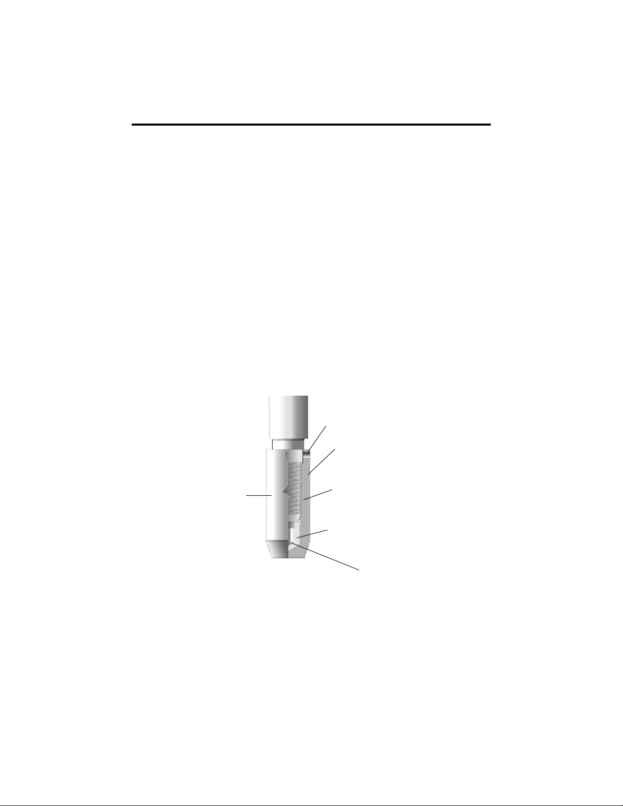
The TempHion is shipped fully assembled, but without filling solution in the reference
electrode. A bottle of filling solution and a plastic syringe are supplied with the instru-
ment. TempHion is shipped with the reference electrode chemically clean and dry, and
the instructions shown below are appropriate for this condition. If you are changing or
replenishing filling solution, or if for any other reason the reference electrode is not
completely clean and dry, please contact INW for proper preparation.
The following steps are needed to put the instrument in service:
1. Remove the white reference electrode outer housing.
CAUTION: Do not grasp the sensing electrodes.
2. Fill the white reference electrode outer housing with reference electrode filling
solution about half full.
3. With a clean tissue, wipe off any droplets of filling solution from the threads of
the bottle and bottle cap and the top and inside of the neck. Replace the red seal
and cap.
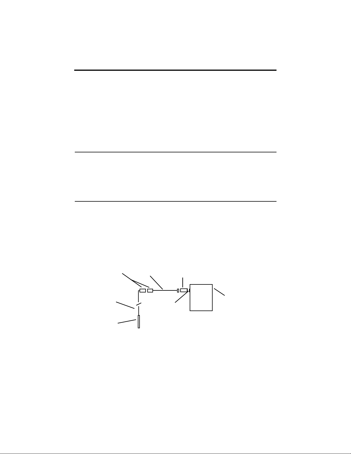
4. Holding the TempHion vertical, with the reference electrode pointing down,
reattach the outer housing. Excess solution will be forced out the top of the
outer housing. Tighten firmly. Do this over a sink, bucket, or other waste
container.
CAUTION: Filling solutions are not considered hazardous, but they can be
irritating to the skin, so rubber gloves are advised. Rinse hands or gloves with
fresh water.

6
5. Keep the TempHionTM sensor vertical or near vertical and place in water. Once
the reference electrode is filled, the device must be stored in water or calibra-
tion solution. Otherwise, the filling solution will evaporate, and air bubbles and/
or crystallized salts can cause an open circuit in the measurement cell.
INW generally recommends that the instrument be stored in the lowest concentration
calibration standard to be used. First, however, rinse the TempHionTM with a small
portion the calibration solution to remove excess filling solution, then place it in fresh
calibration solution. Convenient containers for storage and calibration can be made
from 1¼-inch PVC pipe, 14 inches in length, with a cap cemented to one end.
Connecting External Power
The TempHionTM comes with two AA internal batteries. If auxiliary power is desired, you
can use a 6 - 13 VDC supply that can provide 15 mA. Connect to Vaux++ (white) and
Ground (blue) or contact INW for auxiliary power connectors.
Connecting the TempHionTM to a Computer
The Smart Sensor cable is terminated with a weatherproof connector. Connect the
weatherproof connector to your PC or laptop serial port via the interface cable and an
RS485/RS232 adapter, as shown below. For USB connections, see Appendix E.
Figure 2: Connecting the Sensor to a Computer
PC or Laptop
Computer
RS485/RS232
Adapter
Interface
Cable
Weather-
proof
Connectors
Serial Port
Sensor
Sensor
Cable

7
Installing the Aqua4Plus Software
The TempHionTM comes with the Aqua4Plus host software to be installed on your PC or
laptop. Use this software to calibrate the sensor, to program the datalogger, to retrieve
data from the logger, to view collected data, and to export data to external files for use
with spreadsheets or databases. Refer to the Aqua4Plus software manual for details on
installing and using Aqua4Plus.
Calibration
The TempHion has two temperature channels and four millivolt channels. The millivolt
channels can be configured to measure pH, redox, or various selected ions. Before
leaving the factory, your sensor has been configured specifically for you. All unneeded
channels have been disabled, and the active channels have been pre-configured.
Disabled channels will not display in Aqua4Plus.
All active channels can be calibrated in the field. Temperature channels rarely need
calibrating, however the millivolt channels should be calibrated before first use and
periodically thereafter.
Environmental conditions of turbulence and temperature swings, as well as local
likelihood for biofouling or mineral deposition, can vary considerably from site to site.
Therefore, where the sensor is to be used for long-term monitoring, it is recommended
that the calibration be initially checked frequently until a performance history is estab-
lished.
See Appendix A for detailed calibration instructions.
Field Deployment
Once the TempHionTM Smart Sensor as been calibrated, it should be stored vertically in
water or a calibration solution until it is placed in service at the field site.
Lower the sensor to the desired depth. Fasten the cable to the well head using tie
wraps or a weather proof strain-relief system. (Note that for shallow installations the
liquid in which the sensor is submerged must, at all times, reach high enough to touch
the metal tubing on the sensor.)
Be sure the supplied cap is securely placed on the weather-proof connector at the top of
the cable. Do not install such that the connector might become submerged with chang-
ing weather conditions. The connector can withstand incidental splashing but is not
designed to be submerged.

8
Collecting Data
Following is a brief overview on using Aqua4Plus to collect data. Please refer to the
Aqua4Plus Instruction Manual for further details on configuring and using Aqua4Plus.
Real Time Monitor
Figure 3: Real Time Monitor
Setting up a Data Recording Session
Click the tool button. A Session Profile Window will open. Refer to the Aqua4Plus
Instruction Manual for details in describing your session profile. Click the Start button
to save the session to the sensor and begin recording.
Figure 4: Session Profile Window
Click Single to get a single
reading.
Click Start to get a reading
once a second.
Click Stop to stop the reading.
Note: These are snapshot
readings and are not recorded
on the sensor.

9
•Click on the session you want to upload.
•Click the tool button.
•Select a file location.
•Click Save.
•Click Start.
Figure 5: Session to Upload
Retrieving Data from the Sensor/Datalogger
Viewing Data
•Click the tool button to view data as a table.
•Click the tool button to view data as a graph.
•Navigate to the desired file, then click the Open button. (If the File Open box does
not appear, click the File Menu, then select Open.)
Figure 6: File Display Window

10
Figure 7: Graph Window
Exporting Data to .csv or .xls Files
•Using the File Display window, open the file you want to export.
•Click on the tool button.
•Select a file location and enter a name for the file.
•Select a file type.
•Click Save.
AWordAbout Units
Readings from the TempHionTM Smart Sensor can be displayed in various units . Select
the units you want from the Options | Units menu.
pH: pH or mV
ISE: ppm or mV
Redox: mVH or mV
Temperature: Degrees Celsius, Fahrenheit, or Kelvin
When using pH, ppm, or mVH units, all readings are automatically compensated for
temperature and all field calibration factors are applied. When using millivolts or ohms,
only the actual millivolt or resistance values are displayed - no adjustments are made.

11
Appendix A: Field Calibration
Calibration Overview
Environmental conditions of turbulence and temperature swings, as well as local
likelihood for biofouling or mineral deposition, can vary considerably from site to site.
Therefore, where the sensor is to be used for long-term monitoring, it is recommended
that the calibration be initially checked frequently until a performance history is estab-
lished.
Aqua4Plus provides a one- and two-point calibration utility for performing in-field
calibrations. Two-point calibrations are more accurate and should be used whenever
possible.
Following is a general overview of how to use the field calibration utility. As specific
channel types vary slightly, see the next section for detailed calibration instructions for
each channel type.
To begin calibration, connect the sensor to your computer as detailed previously. Scan
for sensors and click on the sensor you want to calibrate. (For details in using
Aqua4Plus, see the Aqua4Plus Instruction Manual.)
Calibration can only be done when there are no sessions stored on the sensor. If there
are any sessions stored on the sensor, upload any data you want and then erase the
sessions before continuing. (Sessions Menu | Erase All Sessions).
From the Configure Menu, select Field Calibration. The Field Calibration and Settings
window will display. (See figure 8.)
Explanation of Fields
(Letters below refer to circled letters on figure 8.)
(A) List of active channels: Click on the channel you want to calibrate.
(B) Channel Label: If desired, enter a custom label for this channel, up to 20
characters. This label will display on screen and in uploaded data.
(C) Calibration Date: When this channel is calibrated, the date of calibration is
saved in this field. It also displays on uploaded and exported data.
(D) Calibration Values: These values are computed during calibration. The values
will be different for different channel types.
(E) Reference Values: These fields record the reference points used during
calibration.
(F) Calibration Temperature: This is the temperature of the first calibration solution
in degrees Celsius.
(G) Comment Field: Use this field to optionally record a comment about this
channel. This is saved on the sensor and can be viewed from this window. It is
not included in uploaded data.

12
Figure 8: Field Calibration and Settings Window
Using the Calculator
Use the built-in calibration calculator to perform the calibration. Different channel types
will vary slightly, but the general process is as follows. (See the next section for specific
details on each channel type.) You will need one or two known solutions, depending
on whether you are doing a one- or two-point calibration.
•To begin calibration, place the sensor in the first known solution.
•(H1) Enter the first reference value that you are using during calibration. This
may be a known temperature if calibrating a temperature channel, a pH value if
calibrating a pH channel, etc.
•(J1) Click the first Measure button.Ameasurement box will pop up (figure 9).
Click OK inthe pop-up box when readings have stabilized to your satisfaction.
(If doing a one-point calibration, skip the next three steps.)
•Place the sensor in the second solution.
•(H2) Enter the second reference value that you are using during calibration.
•(J2) Click the second Measure button. Click OK in the pop-up box when
readings have stabilized to your satisfaction.
•(K) Observe the calibration values.
•(L) Click the Apply button to apply the calibration values. The fields on the top
of the form will be updated.
•(M) Click OK to save the values to the sensor.

13
Figure 9: Pop-up Measurement Box
Field Calibration for Thermistor Channels
Thermistor channels can be calibrated in degrees Celsius, Fahrenheit, or Kelvin. Select
the units from the Options menu.
One-PointCalibration:
— Computing Calibration Value —
•Place sensor in water. Allow time for the sensor to reach thermal equilibrium.
•Using an accurate alternate measuring device, measure the temperature of the
water.
•In the Ref deg box for the first point, enter this temperature.
•Click first Measure button.
•When readings have stabilized to your satisfaction, click the OK button in the
pop-up box.
— Applying Calibration Value —
•Click the Apply button to apply the calibration value.
•The computed b value will be transferred to the calibration field.
•Click OK to save the value to the sensor.
Two-PointCalibration:
— First Calibration Point —
•Place sensor in water at first temperature. Allow time for the sensor to reach
thermalequilibrium.
•Using an accurate alternate measuring device, measure the temperature of the
water.
•In the Ref deg box for the first point, enter this temperature.
•Click first Measure button.
•When readings have stabilized to your satisfaction, click the OK button in the
pop-up box.

14
— Second Calibration Point —
•Place sensor in water at second temperature. Allow time for the sensor to reach
thermalequilibrium.
•Using an accurate alternate measuring device, measure the temperature of the
water.
•In the Ref deg box for the second point, enter this temperature.
•Click second Measure button.
•When readings have stabilized to your satisfaction, click the OK button in the
pop-up box.
— Applying Calibration Values —
•Click the Apply button to apply the calibration values.
•The computed m and b values will be transferred to the calibration fields.
•Click OK to save the values to the sensor.
Field Calibration for pH Channels
Preparation
•INW recommends pH buffers of 4, 7, and 10 for calibration. For a one-point
calibration, select the buffer closest to the expected values in your samples. For a
two-point calibration, select the two buffers that most closely bracket the expected
values in your samples.
•On the label for each pH buffer, look up the actual pH for the temperature closest
to the temperature of the buffers during calibration.
One-Point Calibration
— First Calibration Point —
•Prepare the buffer.
•Rinse sensor first with distilled water and then with small amount of the buffer.
•Place sensor in buffer. (Buffer must be deep enough to contact stainless steel tube
above the probe section.)
•Allow the sensor to stabilize.
•In the Ref pH box for the first point, enter the reference pH as noted in the
preparation section above.
•Click first Measure button.
•When readings have stabilized to your satisfaction, click the OK button in the
pop-up box.
— Applying Calibration Values —
•Click the Apply button to apply the calibration values.
•The reference value, the computed I, and the sample temperature will be trans-
ferred to the calibration fields.
•Click OK to save the values to the sensor.

15
Two-Point Calibration
— First Calibration Point —
•Prepare first buffer.
•Rinse sensor first with distilled water and then with small amount of first buffer.
•Place sensor in buffer. (Buffer must be deep enough to contact stainless steel tube
above the probe section.)
•Allow the sensor to stabilize.
•In the Ref pH box for the first point, enter the reference pH as noted in the prepara-
tion section above.
•Click first Measure button.
•When readings have stabilized to your satisfaction, click the OK button in the
pop-up box.
— Second Calibration Point —
•Prepare the second buffer.
•Rinse sensor first with distilled water and then with small amount of second buffer.
•Place sensor in second buffer. (Buffer must be deep enough to contact stainless
steel tube above the probe section.)
•In the Ref pH box for the second point, enter the reference pH as noted in the
preparation section above.
•Click second Measure button. (Note: measured temperature must be +/- 1 degree
of first measured temperature or calibration will not be accurate!)
•When readings have stabilized to your satisfaction, click the OK button in the
pop-up box.
— Applying Calibration Values —
•Click the Apply button to apply the calibration values.
•The reference values, the computed M and I, and the sample temperature will be
transferred to the calibration fields.
•Click OK to save the values to the sensor.
Field Calibration for ISE (Selective Ion) Channels
Preparing
•Make a best-guess estimate as to what the range of concentration of the specific
ion will be in the sample you will be measuring.
•Select a standard for that ion, as follows:
•If the expected concentration is between 0 and 10 ppm, use a 100 ppm standard.
•If the expected concentration is between 10 and 100 ppm, use a 1000 ppm
standard.
•If the expected concentration is between 100 and 1000 ppm, use a 10,000 ppm
standard.
•Place 100 mL of room temperature distilled water in a beaker.
Note: Temperature of the water must remain the same throughout the calibra-
tion. Temperature of the probe must also be this temperature prior to calibration.

16
One-Point Calibration
— Computing Calibration Value —
•Rinse sensor in room temperature distilled water and pat dry.
•Place sensor in beaker of distilled water, as prepared on previous page. (Solution
must be deep enough to contact stainless steel tube above the probe section.)
•Add 1 cc of selected standard to the water. This will result in a concentration of
.99 for 100 ppm standard, 9.9 ppm for a 1000 ppm standard, or 99.9 for 10,000 ppm
standard.
•Stir to distribute standard evenly.
•Allow sensor to stabilize.
•In the Ref ppm box for the first point, enter the concentration you have chosen.
•Click the first Measure button.
•When readings have stabilized to your satisfaction, click the OK button on the
pop-up box.
— Applying Calibration Values —
•Click the Apply button to apply the calibration values.
•The reference value, the computed I, and the sample temperature will be trans-
ferred to the calibration fields.
•Click OK to save the values to the sensor.
Two-Point Calibration
— First Calibration Point —
•Rinse sensor in room temperature distilled water and pat dry.
•Place sensor in beaker of distilled water, as prepared on previous page. (Solution
must be deep enough to contact stainless steel tube above the probe section.)
•Add 1 cc of selected standard to the water. This will result in a concentration of
.99 for 100 ppm standard, 9.9 ppm for a 1000 ppm standard, or 99.9 for 10,000 ppm
standard.
•Stir to distribute standard evenly.
•Allow sensor to stabilize.
•In the Ref ppm box for the first point, enter the concentration you have chosen.
•Click the first Measure button.
•When readings have stabilized to your satisfaction, click the OK button on the
pop-up box.
— Second Calibration Point —
•Add 10 cc of the same standard to the water. This will result in a concentration of
9.9 for 100 ppm standard, 99 ppm for a 1000 ppm standard, or 990 for 10,000 ppm
standard.
•Stir to distribute standard evenly.
•Allow electrodes to stabilize.
•In the Ref ppm box for the second point, enter the concentration you have chosen.
•Click the second Measure button.

17
•When readings have stabilized to your satisfaction, click the OK button on the
pop-up box.
— Applying Calibration Values —
•Click the Apply button to apply the calibration values.
•The reference values, the computed M and I, and the sample temperature will be
transferred to the calibration fields.
•Click OK to save the values to the sensor.
Field Calibration for Redox Channels
— Computing Calibration Value —
•Place sensor in solution with a known mVH. (Solution must be deep enough to
contact stainless steel tube above the probe section.)
•Allow time for the sensor to reach equilibrium.
•In the Ref mVH box enter the mVH of the solution you are using.
•Click Measure button.
•When readings have stabilized to your satisfaction, click the OK button in the
pop-up box.
— Applying Calibration Value —
•Click the Apply button to apply the calibration value.
•The computed offset value will be transferred to the calibration field.
•Click OK to save the value to the sensor.

18
Appendix B: Technical Specifications
Wiring Information
Cable Type: 9-conductor, shielded
Shield = Ground
White = Vaux (6 to 13 VDC)
Brown = Digital out
Orange = Vbat+ (1.8 to 3.3 VDC)
Blue = Ground
Yellow = Comm D+
Purple = Comm D-
Operating Specifications
pH
Accuracy (typical) ± 0.2 pH units
Resolution 0.001 pH units
ISE
Accuracy (typical) ± 5% of reading
Resolution 0.1ppm
Redox
Accuracy (typical) ±20mV
Resolution 0.1mVH
Temperature
Accuracy ±0.5° C(maximum)
Resolution 0.1°C
Time
Accuracy ± 6 sec/day ± 2 sec/day (typical)
RecommendedOperating
TemperatureRange 0° C to 40° C
Contact factory for extended temperature ranges.

19
Mechanical Specifications
Sensor
Length: 13.5” to 17.0” depending on configuration
O.D. 0.84”
Body Material Delrin®and 316 stainless steel
SealMaterials Viton®and Teflon®
ReferenceElectrode Patented capillary liquid junction with Ag/AgCl electrode
ReferenceElectrolytes TempHion - no heavy metals and non-contaminating
Thermistor 30KOhm
pH Electrode General purpose glass
ChlorideElectrode Solid state
BromideElectrode Solid state
Redox Platinum
Weight 1 lbs.
Cable
OD 0.28”maximum
BreakStrength 138 lbs.
Weight 4 lbs. per 100 feet
Power Supply
Internal 2 AA Alkaline Batteries
Auxiliary 6 - 13 VDC, 15 mA
Other manuals for AquiStar TempHion
1
Table of contents
Other INW Accessories manuals