INW AquiStar PT12-BV User manual

AquiStar®PT12-BV
Barometric Compensator/Vacuum Sensor
INSTRUCTION MANUAL

1
Information in this document is subject to change without notice and does not
represent a commitment on the part of the manufacturer. No part of this manual may
be reproduced or transmitted in any form or by any means, electronic or mechanical,
including photocopying and recording, for any purpose without the express written
permission of the manufacturer.
©1997 - 2015 Instrumentation Northwest, Inc.
Registered trademarks and trademarks belong to their respective owners.
Table of Contents
Introduction .............................................................................................................................2
PT12-BV Compensator/Vacuum Sensor..........................................................................2
Initial Inspection and Handling........................................................................................2
Do’s and Don’ts................................................................................................................2
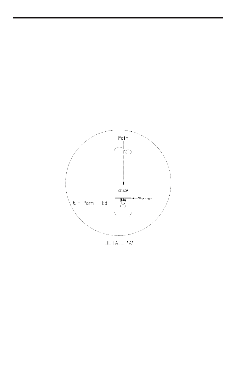
How Pressure Sensors Work....................................................................................................3
Installation & Operation ..........................................................................................................5
Installing the Box Version................................................................................................5
Installing the Tube Version...............................................................................................5
Sensor/Datalogger Configuration.....................................................................................5
Maintenance.............................................................................................................................6
Trouble Shooting......................................................................................................................7
Erratic Readings...............................................................................................................7
Zero Readings...................................................................................................................7
Grounding Issues..............................................................................................................7
Appendix A: Technical Specifications.....................................................................................8
Diagram — PT12-BV Tube Version................................................................................8
Diagram — PT12-BV Barometric/Vacuum Unit.............................................................8
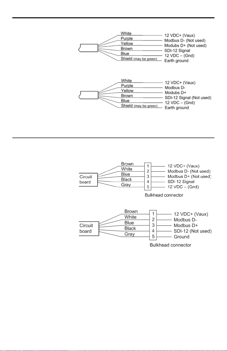
Cable Wiring Information ................................................................................................9
Wiring for Barometric Compensation Units (SDI-12 only).............................................9
Wiring for Barometric Compensation Units (SDI-12 only)...........................................10
Mechanical Specifications..............................................................................................11
Operational Specifications .............................................................................................12
General Specifications....................................................................................................12
Communication..............................................................................................................12
Appendix B: Reading via SDI-12 .........................................................................................13
SDI-12 Command Nomenclature...................................................................................13
SDI-12 Commands.........................................................................................................13
Calibration Register Definitions.....................................................................................18
Appendix C: Reading via Modbus®RTU..............................................................................19
Register Definitions........................................................................................................19
Readings and the Auto-Enable Setting...........................................................................21
Reordering Information .........................................................................................................21
Limited Warranty/Disclaimer — PT12-BV Sensor...............................................................22

2
Introduction
PT12-BV Compensator/Vacuum Sensor
The PT12-BV comes in three versions: as a weatherproof box, as a 316 stainless or
titanium tube, or as an automatic barometric compensator. The PT12-BV measures
pressure, temperature, and supply voltage.
The weatherproof box and tube versions are sand-alone barometric/vacuum sensors
and are ideal barometric references for absolute pressure sensors. The tube version is
available with either a standard closed end cone or a 1/4”NPT end cone for in-pipe
pressure measurements or vacuum extraction applications. These versions feature both
an SDI-12 interface and a Modbus®RTU interface that makes the product easy to
connect to recorders, and operates on low power. This makes it a preferred choice for
many environmental professionals with existing SDI-12 or Modbus®RTU systems.
The compensator version automatically provides barometric compensation for a single
attached absolute PT12 submersible pressure sensor. No post processing of data. No
need to use a vented cable or worry about maintaining desiccant tubes. This
version features an SDI-12 communication interface, making it ideal for many existing
environmental systems.
Initial Inspection and Handling
Upon receipt of your equipment, inspect the shipping package for damage. If any
damage is apparent, note the signs of damage on the appropriate shipping form. After
opening the carton, look for concealed damage such as a cut cable. If concealed
damage is found, immediately file a claim with the carrier.
Do’s and Don’ts
Do handle the device with care.
Do store the device in a dry, inside area when not in use.
Do install a desiccant tube or chamber if you are doing long-term outdoor
monitoring with a gauge unit.
Don’t install the device so that the connector end is submerged.
Don’t support the device with the connector or with the connectors of an extension
cable. Use a strain relief device to take the tension off the connectors.
Don’t allow the device to free-fall down a well at high velocities as impact damage
can occur.
Don’t bang or drop the device on hard objects.
Don’t disassemble the device. (The warranty is void if transducer is disassembled.)

3
How Pressure Sensors Work
The following paragraphs outline the basics of how pressure is measured using
submersible pressure transducers:
Liquids and gasses do not retain a fixed shape. Both have the ability to flow and are
often referred to as fluids. One fundamental law for a fluid is that the fluid exerts an
equal pressure in all directions at a given level. Further, this pressure increases with
an increasing depth of “submergence”. If the density of a fluid remains constant
(noncompressible...a generally good assumption for water at “normal” pressures and
temperatures), this pressure increases linearly with the depth of “submergence”.
We are all “submerged” in the atmosphere. As we increase our elevation, the pressure
exerted on our bodies decreases as there is less of this fluid above us. It should be
noted that atmospheric pressure at a given level does vary with changes in the weather.
One standard atmosphere (pressure at sea level on a “normal” day) is defined to be 14.7
PSI (pounds per square inch).
There are several methods to reference a pressure measurement (see Figure 1).
Absolute pressure is measured with respect to an ideal vacuum (no pressure). Gauge
pressure is the most common way we express pressure in every day life and is the
pressure exerted over and above atmospheric pressure. With this in mind, gauge
pressure (Pg) can be expressed as the difference between the absolute pressure (Pa)
and atmospheric pressure (Patm): Pg = Pa - Patm
Pressure Diagram

4
To measure gauge pressure, atmospheric pressure is subjected to one side of the
system and the pressure to be measured is subjected to the other. The result is that the
differential (gauge pressure) is measured. A tire pressure gauge is a common example
of this type of device.
Recall that as the level of submergence increases (in an incompressible fluid), the
pressure increases linearly. Also, recall that changes in weather cause the absolute
atmospheric pressure to change. In water, the absolute pressure Pa at some level of
depth (d) is given as follows (see Figure 2):
Pa = Patm + kd
where k is simply a constant (i.e.: 2.307 ft of water = 1 PSI)
Pressure Diagram, Detail “A”
INW’s standard gauge submersible pressure devices utilize a vent tube in the cable
to allow the device to reference atmospheric pressure. The resulting gauge pressure
measurement reflects only the depth of submergence. That is, the net pressure on the
diaphragm (Figure 2) is due entirely to the depth of submergence.

5
Installation & Operation
Installing the Box Version
For Barometric Measurement
The PT12-BV can be installed in any position; however, INW recommends installing
it with the connections facing down to avoid moisture entering the inlet. INW also
recommends installing a sun shield to avoid overheating.
For Vacuum Measurement
If installing a vacuum tube for vacuum measurements, be sure that the tubing is not
collapsible. The unit is provided with a detachable Quick-Connect (QC) with a male
1/8” pipe fitting. Attach the tubing to the QC using an appropriate tube fitting for the
tubing chosen. Attach a fitting to the inlet male QC designed to seal the tubing of your
choice. Seal the fitting to the QC by using sealant of PTFE tape. Connect the male QC
to the inlet QC of the PT12-BV and the other end of the tube to the vacuum source
using appropriate fittings
Installing the Tube Version
The tube version can be installed in any position; however, when it leaves the factory
it is tested in the vertical position. Strapping the transducer body with tie wraps or
tape will not hurt it. INW can provide an optional 1/4” NPT input adapter that is
interchangeable with the standard end cone for those applications where it is necessary
to directly attach the transducer to a pipe, tank or other pipe port.
Sensor/Datalogger Configuration
The PT12 submersible pressure/temperature transducer is designed for use with SDI-12
or Modbus®dataloggers. See Appendix A for wiring information. See Appendix B for
SDI-12 communication or Appendix C for Modbus®communication.
Every sensor is individually calibrated at the factory, using an environmental test
chamber and dead-weight tester. Sensor specific calibration values are stored in the
sensor. When taking measurements, the internal microprocessor uses these calibration
values to thermally compensate the pressure readings.
In addition to the factory-set calibration values, the user can enter a field calibration
slope and offset for the pressure and temperature channels. Pressure readings default to
psi and temperature readings to degrees Celsius. The user can enter a units conversion
slope and offset to change units, if desired. See Appendix B or Appendix C for details
on changing these values.

6
Maintenance
Box/Tube: There are no user-serviceable parts. If problems develop with sensor
stability or accuracy, contact INW. If the units have been exposed to hazardous
materials, do not return them without notification and authorization.
Cable: Cable can be damaged by abrasion, sharp objects, twisting, crimping or
crushing and pulling Take care during installation and use to avoid cable damage.

7
Trouble Shooting
Erratic Readings
Erratic Readings can be caused by a poor connection, moisture in the unit, or a
damaged transmitter. In most cases, erratic readings are due to moisture getting into
the system. The first thing to check is the connection. Look for moisture between
contacts or a loose or broken wire. If the connections appear OK, but the readings are
still erratic, the transmitter may be damaged. Contact INW for evaluation and repair.
Erratic and erroneous readings can also occur due to improper grounding. See
Grounding Issues, below.
Zero Readings
Continuous zero readings are usually caused by and open circuit which may indicate
a bad connection or possible a damaged transmitter. Check the connector to see if a
wire has become loose. If cause of failure is not readily apparent, contact INW for
evaluation and repair.
Grounding Issues
It is commonly known that when using electronic equipment, both personnel and
equipment need to be protected from high power spikes that may be caused by
lightning, power line surges, or faulty equipment. Without a proper grounding system,
a power spike will find the path of least resistance to earth ground—whether that path
is through sensitive electronic equipment or the person operating the equipment. In
order to ensure safety and prevent equipment damage, a grounding system must be used
to provide a low resistance path to ground.
When using several pieces of interconnected equipment, each of which may have its
own ground, problems with noise, signal interference, and erroneous readings may be
noted. This is caused by a condition known as a Ground Loop. Because of natural
resistance in the earth between the grounding points, current can flow between the
points, creating an unexpected voltage difference and resulting erroneous readings.
The single most important step in minimizing a ground loop is to tie all equipment
(sensors, dataloggers, external power sources and any other associated equipment) to
a single common grounding point. INW recommends connecting the shield to ground
at the connector end.

8
Appendix A: Technical Specifications
Diagram — PT12-BV Tube Version
Air
Inlets
Cable to logger
PT12-BV Tube Version
Diagram — PT12-BV Barometric/Vacuum Unit
PT12-BV Barometric/Vacuum Unit
To logger
Vacuum Input
Optional: connection to absolute PT12
Pressure/Temperature unit if configured
for barometric compensation

9
Cable Wiring Information
Cable wiring color codes and connections
Wiring for Barometric Compensation Units (SDI-12 only)
Bulkhead wiring color codes and connections
For Modbus®
For SDI-12
For Modbus®
For SDI-12

10
Wiring for Barometric Compensation Units (SDI-12 only)
Wiring for Barometric Compensation Units
When configured for automatic
barometric compensation, the
surface installed PT12-BV
communicates with the down-
hole PT12 Pressure/Temperature
Sensor via Modbus. The surface
PT12-BV then communicates with
an SDI-12 host or logger to give
compensated pressure readings
for the down-hole sensor. (See
Appendix B for SDI-12 command
information.)

11
Mechanical Specifications
WEATHERPROOF BOX
Enclosure Material ABS - IP66/67
Dimensions (box) 4.3” x 3.1” x 2.5”
(10.9 x 7.9 x 6.4 cm)
Dimensions (incl connectors) 4.3” x 3.6” x 2.5”
(10.0 x 9.1 x 6.4 cm)
Wire Seal Materials Fluorocarbon and Buna N
Communication Pigtail 5” (12.7cm) Polyurethane cable
Options
Wiring a downhole sensor into the BV box Compensator)
Additional wire seal in place of plug
Custom color coding on communication pigtail
Custom length on communication pigtail
Extended temperature range
Enhanced temperature calibration
HIF calibration
TUBE
Body Material 316 stainless steel or titanium
Dimensions (tube) 8.15” x 0.75” diameter
(20.7 x 1.9 cm)
Wire Seal Materials Fluoropolymer and PTFE
Terminating Connector Available
Weight 0.80 lbs. (0.4 kg)
Options
1/4” NPT in place of closed end cone
Extended temperature range
Enhanced temperature calibration
HIF calibration
CABLE
OD 0.28” (0.7 cm) maximum
Break Strength 138 lbs. (62.7 kg)
Maximum Length 2000 feet (610 meters) for Modbus®
200 feet (61 meters) for SDI-12
Weight 4 lbs. per 100 feet (1.8 kg per 30 m)

12
Operational Specifications
PRESSURE / VACUUM
Element 0-16 PSIA (110 kpa)
Accuracy ± 0.1% FSO (maximum)
(B.F.S.L. 25° C)* ± 0.06% FSO (typical)
Maximum Zero Offset ± 0.25% FSO @ 25° C
Over Range Protection 2x
TEMPERATURE
Element Type Digital Temp. Sensor
Accuracy ± 0.5° C
Resolution 0.06° C
Range -40° C to 80° C
POWER
Over Voltage Protection 24 VDC
Power Supply Current Active 3mA Avg./10mA Peak
Power Supply Current Sleep 150 μA
General Specifications
Communication RS485 Modbus RTU
SDI-12 (ver.1.3)
Direct Modbus Read Output 32-bit IEEE Floating point
SDI-12 Output ASCII
Internal Math 32 bit floating point
Operating Voltage 9 - 16 VDC
Compensated Temperature Range -0° C to 40° C
(for extended ranges, contact INW)
Operating Temperature Range -15° C to 55° C
(Freezing protection kit required if water below freezing)
Storage Temperature Range -40° C to 80° C
MISCELLANEOUS
Measurement Latency Approx. 1.3 seconds
Default Address Each sensor’s address is supplied on
documentation accompanying the equipment
Special Addressing When using a PT12 connected to a PT12-BV
for barometric compensation, the down-hole unit
must be at Modbus address 2. The PT12-BV can
be any other Modbus address. This does not affect
SDI-12 addresses.

13
Appendix B: Reading via SDI-12
SDI-12 Command Nomenclature
a = Sensor address
{crc} = SDI-12 compatible 3-character CRC
<cr> = ASCII carriage return character
<lf> = ASCII line feed character
Following commands are shown in the format of:
cmd response // comments
SDI-12 Commands
Query and Setup Commands
//*** Sensor Identification
aI! a13 INWUSA PT120.7ssssssssss<cr><lf> // note: 0.7 will change to reflect
current firmware revision
ssssssssss = device serial #
//*** Acknowledge Active
a! a<cr><lf>
//*** Address Query
?! a<cr><lf>
//*** Change Address
aAb! b<cr><lf> // change address from a to b
Request measurement
aM! a0023<cr><lf> // request pressure/temperature/voltage
measurement
aD0! a+7.15863+25.0000+12.0512<cr><lf> // read pressure (psi),
temperature (°C), voltage (V)
aM1! a0021<cr><lf> // request pressure measurement only
aD0! a+7.15863<cr><lf> // read pressure (psi)
aM2! a0021<cr><lf> // request temperature measurement only
aD0! a+25.0000<cr><lf> // read temperature (°C)
aM3! a0021<cr><lf> // request power supply voltage measurement
aD0! a+12.0512<cr><lf> // read power supply voltage (V)
aM4! a0ttt4<cr><lf> // request averaged data. ttt depends upon
programmed average duration
aD0! a+7.15863+7.23215+7.05128+25.0000<cr><lf>
// read Ave Pressure, Max Pressure,
Min Pressure, Ave Temperature

14
M5!, M6!, and M7! only available on PT12-BV/PT12 combination units!
aM5! a0023<cr><lf> // request barometrically compensated down-hole
pressure, down-hole temperature, surface
temperature measurement
aD0! a+2.58613+19.2100+21.0512<cr><lf> // read barometrically compensated down-hole
pressure, down-hole temperature, surface
temperature
aM6! a0024<cr><lf> // request non-barometrically compensated down-
hole pressure, down-hole temperature, surface
pressure, surface temperature measurement
aD0! a+17.31813+19.2100+14.732+21.0512<cr><lf>
// read non-barometrically compensated down-
hole pressure, down-hole temperature, surface
pressure, surface temperature
aM7! atttl<cr><lf> // request averaged, barometrically compensated
pressure. ttt depends upon programmed
average
aD0! a+7.12050<cr><lf> // averaged barometrically compensated pressure
Request measurement with CRC
aMC! a0023<cr><lf> // request pressure/temperature/voltage
measurement
aD0! a+7.15863+25.0000+12.0512{crc}<cr><lf> // read pressure (psi),
temperature (°C), voltage (V)
aMC1! a0021<cr><lf> // request pressure measurement only
aD0! a+7.15863{crc}<cr><lf> // read pressure (psi)
aMC2! a0021<cr><lf> // request temperature measurement only
aD0! a+25.0000{crc}<cr><lf> // read temperature (°C)
aMC3! a0021<cr><lf> // request power supply voltage measurement
aD0! a+12.0512{crc}<cr><lf> // read power supply voltage (V)
aMC4! a0ttt4<cr><lf> // request averaged data. ttt depends upon
programmed average duration
aD0! a+7.15863+7.23215+7.05128+25.0000{crc}<cr><lf>
// read Ave Pressure, Max Pressure,
Min Pressure, Ave Temperature
MC5!, MC6!, and MC7! only available on PT12-BV/PT12 combination units!
aMC5! a0023<cr><lf> // request barometrically compensated down-hole
pressure, down-hole temperature, surface
temperature measurement
aD0! a+2.58613+19.2100+21.0512{crc}<cr><lf>
// read barometrically compensated down-hole
pressure, down-hole temperature, surface
temperature
aMC6! a0024<cr><lf> // request non-barometrically compensated down-
hole pressure, down-hole temperature, surface
pressure, surface temperature measurement
aD0! a+17.31813+19.2100+14.732+21.0512{crc}<cr><lf>
// read non-barometrically compensated down-
hole pressure, down-hole temperature, surface
pressure, surface temperature

15
aMC7! atttl<cr><lf> // request averaged, barometrically compensated
pressure. ttt depends upon programmed
average
aD0! a+7.12050<cr><lf> // averaged barometrically compensated pressure
Concurrent measurement
aC! a00203<cr><lf> // request pressure/temperature/voltage
measurement
aD0! a+7.15863+25.0000+12.0512<cr><lf> // read pressure (psi),
temperature (°C), voltage (V)
aC1! a00201<cr><lf> // request pressure measurement only
aD0! a+7.15863 // read pressure (psi)
aC2! a00201<cr><lf> // request temperature measurement only
aD0! a+25.0000<cr><lf> // read temperature (°C)
aC3! a00201<cr><lf> // request power supply voltage measurement
aD0! a+12.0512<cr><lf> // read power supply voltage (V)
aC4! a0ttt04<cr><lf> // request averaged data. ttt depends upon
programmed average duration
aD0! a+7.15863+7.23215+7.05128+25.0000<cr><lf>
// read Ave Pressure, Max Pressure,
Min Pressure, Ave Temperature
C5!, C6!, and C7! only available on PT12-BV/PT12 combination units!
aC5! a00203<cr><lf> // request barometrically compensated down-hole
pressure, down-hole temperature, surface
temperature measurement
aD0! a+2.58613+19.2100+21.0512<cr><lf> // read barometrically compensated down-hole
pressure, down-hole temperature, surface
temperature
aC6! a00204<cr><lf> // request non-barometrically compensated down-
hole pressure, down-hole temperature, surface
pressure, surface temperature measurement
aD0! a+17.31813+19.2100+14.732+21.0512<cr><lf>
// read non-barometrically compensated down-
hole pressure, down-hole temperature, surface
pressure, surface temperature
aC7! attt01<cr><lf> // request averaged, barometrically compensated
pressure. ttt depends upon programmed
average
aD0! a+7.12050<cr><lf> // averaged barometrically compensated pressure

16
Concurrent measurement with CRC
aCC! a00203<cr><lf> // request pressure/temperature/voltage
measurement
aD0! a+7.15863+25.0000+12.0512{crc}<cr><lf> // read pressure (psi),
temperature (°C), voltage (V)
aCC1! a00201<cr><lf> // request pressure measurement only
aD0! a+7.15863{crc}<cr><lf> // read pressure (psi)
aCC2! a00201<cr><lf> // request temperature measurement only
aD0! a+25.0000{crc}<cr><lf> // read temperature (°C)
aCC3! a00201<cr><lf> // request power supply voltage measurement
aD0! a+12.0512{crc}<cr><lf> // read power supply voltage (V)
aCC4! a0ttt04<cr><lf> // request averaged data. ttt depends upon
programmed average duration
aD0! a+7.15863+7.23215+7.05128+25.0000{crc}<cr><lf>
// read Ave Pressure, Max Pressure,
Min Pressure, Ave Temperature
CC5!, CC6!, and CC7! only available on PT12-BV/PT12 combination units!
aCC5! a00203<cr><lf> // request barometrically compensated down-hole
pressure, down-hole temperature, surface
temperature measurement
aD0! a+2.58613+19.2100+21.0512{crc}<cr><lf>
// read barometrically compensated down-hole
pressure, down-hole temperature, surface
temperature
aCC6! a00204<cr><lf> // request non-barometrically compensated down-
hole pressure, down-hole temperature, surface
pressure, surface temperature measurement
aD0! a+17.31813+19.2100+14.732+21.0512{crc}<cr><lf>
// read non-barometrically compensated down-
hole pressure, down-hole temperature, surface
pressure, surface temperature
aCC7 attt01<cr><lf> // request averaged, barometrically compensated
pressure. ttt depends upon programmed
average
aD0! a+7.12050<cr><lf> // averaged barometrically compensated pressure

17
Extended Commands
//*** Set duration for averaging reading
aXAttt! attt<cr><lf> // set duration of averaged data for M4 command
// ttt = 1..997 seconds
//*** Read/Modify Calibration Values
aXCnn{=<value>}! a<value><cr><lf> // read{modify} calibration value nn
examples:
aXC00! a+1.591600e-5<CR><LF> // read value of calibration register 00
aXC00=1.704e-4! a+1.704000e-4<CR><LF> // set value of calibration register 00
//*** Set number of significant digits
aXSt! at<cr><lf> // set # of significant digits for SDI-12 report
data
// t = 1..7

18
Calibration Register Definitions
All calibration registers contain floating point values.
SDI-12 Default
REG ID Mnemonic Description Value
_______________________________________________________________________
00 Scale Units scale 1.591600E-5
(Counts * Scale = base units, default psi)
01 a Factory cal-linearized
correction factor 1 0.000000E+00
02 b Factory cal-linearized
correction factor 2 1.000000E+00
03 m0 Factory cal-slope
coefficient 0 1.000000E+00
04 m1 Factory cal-slope
coefficient 1 0.000000E+00
05 m2 Factory cal-slope
coefficient 2 0.000000E+00
06 b0 Factory cal-offset
coefficient 0 0.000000E+00
07 b1 Factory cal-offset
coefficient 1 0.000000E+00
08 b2 Factory cal-offset
coefficient 2 0.000000E+00
09 mField Field pressure cal-slope 1.000000E+00
10 bField Field pressure cal-offset 0.000000E+00
11 mT Field temperature cal-slope 1.000000E+00
12 bT Field temperature cal-offset 0.000000E+00
13 T_Alpha Factory Temperature
Cal-Alpha 0.000000E+00
14 T_Offset Factory Temperature
Cal-Offset 0.000000E+00
15 T_ZeroSlope Factory Temperature
Cal-ZeroSlope 0.000000E+00
16 P_mUnits Pressure units
conversion slope 1.000000E+00
17 P_bUnits Pressure units
conversion offset 0.000000E+00
18 T_mUnits Temperature units
conversion slope 1.000000E+00
19 T_bUnits Temperature units
conversion offset 0.000000E+00
Factory calibration values are set at the factory.
Writing to Factory Calibration registers will void calibration!!
Field calibration values can be set by user. If set, these values will be applied to
readings before values are returned.

19
Appendix C: Reading via Modbus®RTU
Register Definitions
Communication settings and Modbus®functions
The PT12 is configured to communicate with 8 data bits, one stop bit, and no parity.
Read the values using function 03-Read Holding Registers. Default baud rate is 19200.
Parameter data
32-bit ieee floating point values, read-only
These registers must be read as pairs
40001-2 Pressure (psi)
40003-4 Temperature (degrees C)
40005-6 Power supply voltage (volts)
Statistical data values
40007-8 Averaged pressure
40009-10 Maximum pressure
40011-12 Minimum pressure
40013-14 Averaged temperature
Calibration and conversion constants
The data is returned as a 32-bit IEEE floating-point value, high word first, also referred
to as big-endian, float inverse, or Float AB CD.
Register Mnemonic Description
40201-2 Scale Factory calibration - Pressure units scale
40203-4 a Factory calibration - Pressure linearization 1
40205-6 b Factory calibration - Pressure linearization 2
40207-8 m0 Factory calibration - Pressure slope 0
40209-10 m1 Factory calibration - Pressure slope 1
40211-12 m2 Factory calibration - Pressure slope 2
40213-14 b0 Factory calibration - Pressure offset 0
40215-16 b1 Factory calibration - Pressure offset 1
40217-18 b2 Factory calibration - Pressure offset 2
40219-20 mField Field calibration - Pressure slope
40221-22 bField Field calibration - Pressure offset
40223-24 mT Field calibration - Temperature slope
40225-26 bT Field calibration - Temperature offset
40227-28 T_Alpha Factory calibration - Temperature alpha
40229-30 T_Offset Factory calibration - Temperature offset
40231-32 T_ZeroSlope Factory calibration - Temperature slope
40233-34 P_mUnits Pressure Units - Conversion slope
40235-36 P_bUnits Pressure Units - Conversion offset
40237-38 T_mUnits Temperature Units - Conversion slope
40239-40 T_bUnits Temperature Units - Conversion offset
Table of contents
Other INW Accessories manuals