INW PT2X User manual

19026 72nd Avenue South
Kent, WA 98032 USA
253.872.0284
FAX 253.872.0285 / [email protected]
INW, A Division of Seametrics
INW PT2X
Pressure/Temperature Smart Sensor and Datalogger
©1997 - 2016 Seametrics. All rights reserved. Instrumentation Northwest and INW are trademarks of Seametrics.
Doc# 9B0730r20.1 1/6/2016 / PN 6D275-NI
INSTRUCTION MANUAL
For PSIG
sensors, refer
to page 12
regarding
desiccant
use!

INW - PT2X Instruction Manual 1
Table of Contents
Introduction ......................................................................................................................3
What is the PT2X?.....................................................................................................3
Initial Inspection and Handling .................................................................................3
Do’s and Don’ts.........................................................................................................4
How Pressure Sensors Work......................................................................................4
Installation and Operation.................................................................................................6
Connecting External Power.......................................................................................6
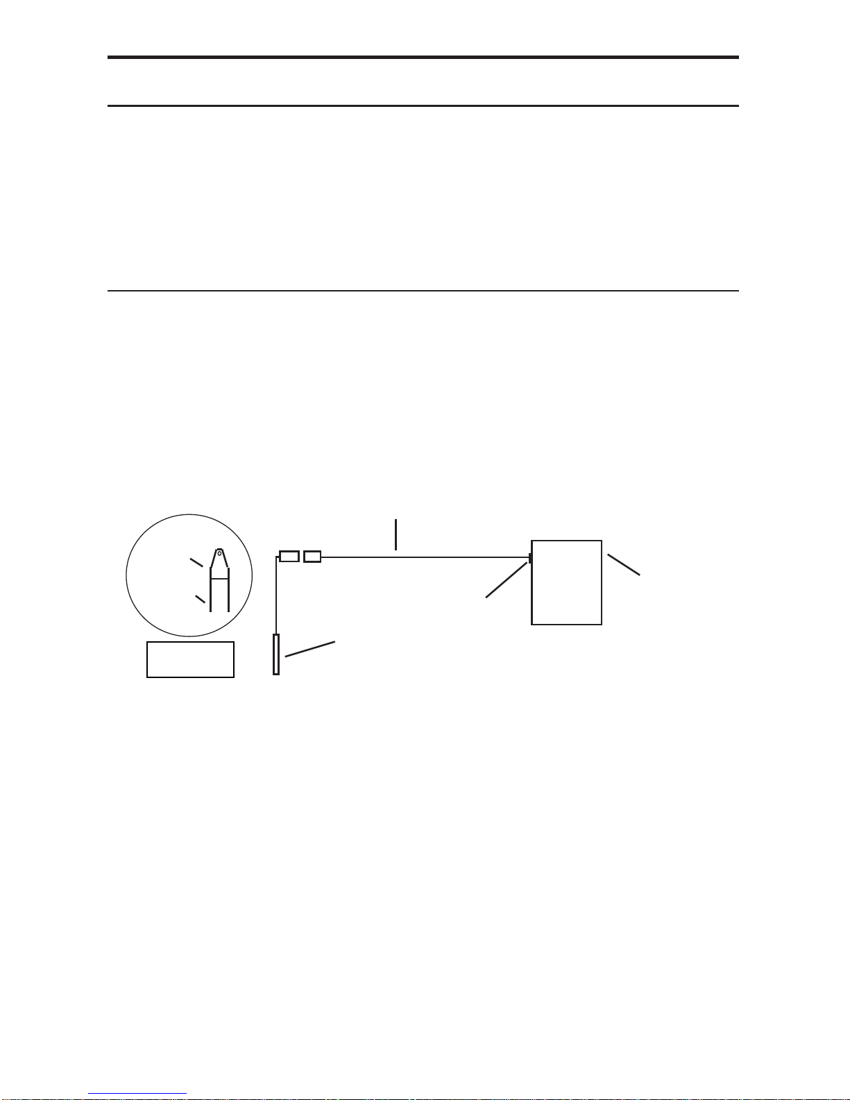
Connecting the PT2X to a Computer.........................................................................6
Installing the Aqua4Plus or Aqua4Plus Lite Software ..............................................7
Installing the Sensor ..................................................................................................7
Battery Life Calculator..............................................................................................8
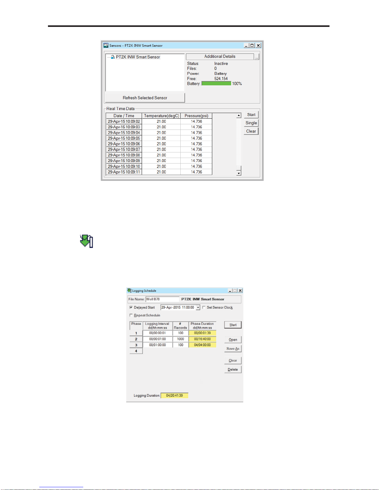
Collecting Data..........................................................................................................8
Maintenance....................................................................................................................12
Changing Batteries...................................................................................................12
Removing Debris from End Cone ...........................................................................12
Desiccant Tubes.......................................................................................................13
Miscellaneous..........................................................................................................14
Trouble Shooting.............................................................................................................14
Erratic Readings.......................................................................................................14
Oscillating Readings Over Time..............................................................................15
Zero Readings When Pressurized............................................................................15
Grounding Issues.....................................................................................................15
Appendix A: Technical Specifications............................................................................16
Wiring and Component Information........................................................................16
Dimensions and Specifications................................................................................17
Continuous Rate and Filter Settings........................................................................19
Appendix B: Settings and Calibration ...........................................................................20
Preparation...............................................................................................................20
Submergence............................................................................................................22
Depth-to-Water ........................................................................................................23
Elevation Above Sea Level......................................................................................24
Staff Gauge..............................................................................................................25
Appendix C: Alternate Connection Options...................................................................26
Connecting via RS232 Serial Port...........................................................................26
Connecting with a USB/Serial Adapter...................................................................26
Appendix D: Reading the PT2X via Direct Read..........................................................28
Setting Units for Direct Read ..................................................................................28
Power Consideration................................................................................................29
Reading Via Modbus®RTU.....................................................................................29
Reading Via SDI-12.................................................................................................31
Appendix E: Battery Changing Details...........................................................................33
Reordering Information ..................................................................................................38
Limited Warranty/Disclaimer - INW PT2X Pressure/Temperature Sensor....................39

2 INW - PT2X Instruction Manual
Information in this document is subject to change without notice and does not
represent a commitment on the part of the manufacturer. No part of this manual may
be reproduced or transmitted in any form or by any means, electronic or mechanical,
including photocopying and recording, for any purpose without the express written
permission of the manufacturer.
©1997 - 2016 Seametrics. All rights reserved.
Registered trademarks and trademarks belong to their respective owners.

INW - PT2X Instruction Manual 3
Introduction
What is the PT2X?
INW’s AquiStar® PT2X Smart Sensor is an integrated datalogger and pressure/
temperature sensor and is ideal for monitoring groundwater, well, tank, and tidal
levels, as well as for pump and slug testing. This sensor networks with all of the INW
AquiStar®Smart Sensor family. Its compatibility with INW’s Wireless Data Collection
technology makes it ideal for remote monitoring.
This industry standard digital RS485 interface device records up to 520,000 records of
pressure, temperature, and time data, operates with low power, and features easy-to-
use software with powerful features. Constructed with 316 stainless steel or titanium,
PTFE, and fluoropolymer, this sensor provides high-accuracy readings in rugged and
corrosive field conditions.
Two internal AA batteries power the PT2X. (Auxiliary power supplies are available
for data intensive applications.) The unit is programmed using INW’s easy-to-use
Aqua4Plus or Aqua4Plus Lite control software. Once programmed the unit will
measure and collect data on a variety of time intervals.
Replace your analog sensor / datalogger with the AquiStar®PT2X as a stand-alone
unit or network with other INW Smart Sensors. Most users will use the PT2X with
INW’s Aqua4Plus or Aqua4Plus Lite software. However, the PT2X is quite versatile,
communicating via either Modbus®or SDI-12 interfaces, allowing you to do the
following:
• Read a PT2X via the Modbus®protocol using your own software.
• Read a PT2X via SDI-12 protocol.
• Display readings from a PT2X on a panel meter.
Initial Inspection and Handling
Upon receipt of your smart sensor, inspect the shipping package for damage. If any
damage is apparent, note the signs of damage on the appropriate shipping form. After
opening the carton, look for concealed damage, such as a cut cable. If concealed
damage is found, immediately file a claim with the carrier.
Check the etched label on the sensor to be sure that the proper range and type were
provided. Also check the label attached to the cable at the connector end for the proper
cable length.

4 INW - PT2X Instruction Manual
Do’s and Don’ts
How Pressure Sensors Work
Liquids and gasses do not retain a fixed shape. Both have the ability to flow and are
often referred to as fluids. One fundamental law for a fluid is that the fluid exerts an
equal pressure in all directions at a given level. Further, this pressure increases with
an increasing depth of “submergence”. If the density of a fluid remains constant
(noncompressible...a generally good assumption for water at “normal” pressures and
temperatures), this pressure increases linearly with the depth of “submergence”.
We are all “submerged” in the atmosphere. As we increase our elevation, the pressure
exerted on our bodies decreases as there is less of this fluid above us. It should be
noted that atmospheric pressure at a given level does vary with changes in the weather.
One standard atmosphere (pressure at sea level at 20º C) is defined to be 14.7 PSI
(pounds per square inch).
There are several methods to reference a pressure measurement. Absolute pressure is
measured with respect to an ideal vacuum (no pressure). Gauge pressure is the most
common way we express pressure in every day life and is the pressure exerted over and
above atmospheric pressure. With this in mind, gauge pressure (Pg) can be expressed
as the difference between the absolute pressure (Pa) and atmospheric pressure (Patm):
Pg = Pa - Patm.
To measure gauge pressure, atmospheric pressure is subjected to one side of the
system and the pressure to be measured is subjected to the other. The result is that the
differential (gauge pressure) is measured. A tire pressure gauge is a common example
of this type of device.
Recall that as the level of submergence increases (in a noncompressible fluid), the
pressure increases linearly. Also, recall that changes in weather cause the absolute
atmospheric pressure to change. In water, the absolute pressure (Pa) at some level of
depth (d) is given as follows:
Pa = Patm + kd
where k is simply a constant (i.e.: 2.307 feet of water = 1 PSI)
Don’t support the device with the connector.
Use a strain relief device to take the
tension off the connectors.
Don’t allow the device to free-fall down a
well as impact damage can occur.
Don’t bang or drop the device on hard
objects.
Do handle the device with care.
Do store the device in a dry, inside area
when not in use.
Do install a desiccant tube if using a gauge
sensor.
Do install the device so that the connector
end is kept dry.

INW - PT2X Instruction Manual 5
INW’s standard gauge submersible pressure devices utilize a vent tube in the cable
to allow the device to reference atmospheric pressure. The resulting gauge pressure
measurement reflects only the depth of submergence. That is, the net pressure on the
diaphragm is due entirely to the depth of submergence.
Pressure Diagram: See detail A.
Absolute pressure is given as Pa = Patm + kd
(where k is 2.307 feet of water)

6 INW - PT2X Instruction Manual
Installation and Operation
Connecting External Power
The PT2X comes with two AA internal batteries.
If auxiliary power is desired, you can use a 6 - 13 VDC supply that can provide 15
mA. Connect to Vaux++ (pin 1 - white) and Ground (pin 5 - blue) or contact INW for
auxiliary power supplies.
Connecting the PT2X to a Computer
In its cabled configuration, the sensorcable is terminated with a weather-resistant
connector. In its cableless configuration, the sensor is terminated with a weather-
resistant connector inside a screw-cap. Connect the weather-resistant connector to
your computer’s USB port as shown below. (For alternate connection options, see
Appendix C.)
Connect the sensor to your PC using INW’s USB to RS485
adapter. (See Appendix C for alternate connections.)
PC or Laptop
Computer
USB Port
USB to RS485
Adapter
Sensor
Cableless
Configuration
Screw-
Sensor
cap

INW - PT2X Instruction Manual 7
Installing the Aqua4Plus or Aqua4Plus Lite Software
The PT2X comes with the Aqua4Plus or Aqua4Plus Lite host software that is installed
on your PC or laptop. Use this software to program the datalogger, to retrieve data
from the logger, to view collected data, and to export data to external files for use with
spreadsheets or databases.
Refer to the software manuals for details on installing and using Aqua4Plus or
Aqua4Plus Lite.
Using the PT2X Without Aqua4Plus or Aqua4Plus Lite
Most users will use the PT2X with INW’s Aqua4Plus or Aqua4Plus Lite software.
However, the PT2X is quite versatile, communicating via either Modbus®or SDI-12
interfaces, allowing you to do the following:
• Read a PT2X via the Modbus®protocol using your own software.
• Read a PT2X via SDI-12 protocol.
• Display readings from a PT2X on a panel meter.
If you want to use one of these methods, see Appendix D.
Installing the Sensor
The PT2X measures pressure. The most common application is measuring liquid
levels in wells and tanks. In order to do this, the sensor must be installed below the
water level at a fixed depth. The installation depth depends on the range of the sensor.
One (1) PSI is equal to approximately 2.31 feet of water. If you have a 5 PSI sensor,
the range is 11.55 feet of water and the sensor should not be installed at a depth below
11.55 feet. If the sensor is installed below its maximum range, damage may result to
the sensor and the output reading will not be correct.
Lower the sensor to the desired depth. Fasten the cable to the well head using tie
wraps or a weather proof strain-relief system. When securing a vented cable, make
sure not to pinch the cable too tightly or the vent tube inside the cable jacket may
be sealed off. Take a measurement to insure the sensor is not installed below its
maximum range.
Be sure the supplied cap is securely placed on the weather-resistant connector at the
top of the cable. Do not install such that the connector might become submerged with
changing weather conditions. The connector can withstand incidental splashing but is
not designed to be submerged.
For vented sensors, install the sensor so that the desiccant tube will not flood or lie in
water.

8 INW - PT2X Instruction Manual
The sensor can be installed in any position; however, when it leaves the factory it is
tested in the vertical position. Strapping the sensor body with tie wraps or tape will not
hurt it. INW can provide an optional 1/4” NPT input adapter which is interchangeable
with the standard end cone for those applications where it is necessary to directly attach
the sensor to a pipe, tank, or other pipe port. If the sensor is being installed in a fluid
environment other than water, be sure to check the compatibility of the fluid with the
wetted parts of the sensor.
Battery Life Calculator
IMPORTANT NOTE for PT2X sensors with firmware 2.13 or higher!
PT2Xs with firmware version 2.13 and higher have a battery life calculator that is
set at the factory when batteries are first put in the sensor. If you need to replace the
batteries, see Appendix E for replacement information and for information on resetting
the battery life calculator. If the battery life calculator is not reset, the remaining life
information will be incorrect.
Collecting Data
Following is a brief overview on using Aqua4Plus/Aqua4Plus Lite to collect data.
Please refer to the software instruction manuals for further details on configuring and
using Aqua4Plus/Aqua4Plus Lite.
Real Time Monitor
Click Single to get a single reading.
Click Start to get a reading once a second for 60 seconds.
Click Stop to stop the reading.
Note: These are snapshot readings and are not recorded on the sensor. On sensors
with firmware versions lower than 2.0, the pressure is displayed in the first column
and temperature in the second. On sensors with firmware versions 2.0 and higher, the
temperature is displayed in the first column and pressure in the second.

INW - PT2X Instruction Manual 9
The Real Time Monitor gives a snapshot of the
current readings on the sensor.
Setting up Data Recording
Click the tool button. A Logging Schedule Window will open. Refer to the
software instruction manuals for details in describing your schedule. Click the Start
button to save the schedule to the sensor and begin recording.
Using the Logging Schedule Window, describe
the test steps for your particular test.

10 INW - PT2X Instruction Manual
Retrieving Data from the Sensor/Datalogger
• Click on the file you want to retrieve.
• Click the tool button.
• Select a file location.
• Click Save.
• Click Start.
Select the data file to retrieve.
Viewing Data
• Click the or tool button to view data as a table.
• Click the tool button to view data as a graph.
• Navigate to the desired file, then click the Open button.
The File Display window displays your
data in a tabular format.

INW - PT2X Instruction Manual 11
The Graph Window displays your data on an X Y
coordinate graph.
Exporting Data to .csv or .xls Files
• Click the or tool button to view data as a table.
• Click on the tool button.
• Select a file location and enter a name for the file.
• Select a file type.
• Click Save.
A Word About Units
Readings from the PT2X Smart Sensor can be displayed in various units, such as PSI,
Ft. H2O, or mm H2O for pressure, or degrees Celsius or degrees Fahrenheit for
temperature. Select the units you want from the Options | Display Units menu or from
the Configure Menu | Program Configuration | Set Computer Display Units.

12 INW - PT2X Instruction Manual
Maintenance
Changing Batteries
Battery Type: Two 1.5V AA batteries.
Because changing the batteries involves opening the water-tight seal, this must be
done in a clean, dry environment to avoid contamination or moisture damage to
the circuitry.
Refer to Appendix E for details on opening the housing and replacing the batteries.
Removing Debris from End Cone
At times mud, silt, or other debris may foul the water inlets to the pressure element.
The end cone can be removed to clean out the debris.
Twist Open Housing
1. Gently twist off end cone portion only - do not twist off pressure element!
2. Remove debris. Take care not to poke anything into the sensor. This can
damage the sensor element and void the warranty.
3. Replace and retighten the end cone.
Gently twist off the end cone, and then carefully remove debris.
Pressure element
Water inlet
End cone
PREVENT BATTERY LEAKAGE!
Under some circumstances the internal batteries can leak, causing damage
to the sensor. To prevent leakage, the following is recommended. (Does not
apply to lithium batteries.)
• Change the batteries at least every 18 months.
• If the sensor will not be deployed for 3 months or more, remove the
batteries.

INW - PT2X Instruction Manual 13
Set Screw Housing
1. Remove the two set screws at the bottom of the housing tube, using a 1/16” allen
wrench.
2. Gently remove the end cone.
3. Remove debris. Take care not to poke anything into the sensor. This can
damage the sensor element and void the warranty.
4. Replace the end cone and secure with set screws.
Remove end cone by removing set screws. Gently clean out debris.
Desiccant Tubes
On vented sensors, inspect the desiccant tube at least once every two months. The
desiccant tube prevents moisture in the air from being sucked into the vent tube, which
can cause erratic readings and sensor damage.
The desiccant tube is filled with blue silica gel beads. A locking barb and a hydrophobic
water filter are attached to the end of the desiccant tube. This filter prolongs the life of
the desiccant as much as three times over a desiccant tube without the filter.
Install the sensor so that the desiccant tube and cable connector will not flood or lie in
water.
The desiccant is a bright blue color when active and dry. As moisture is absorbed the
color will begin to fade, becoming a light pink, which indicates full saturation and time
to replace. Replacement desiccant and hydrophobic filters can be purchased from INW;
please contact an INW sales engineer for more information.
To Change the Desiccant:
• Pulling gently remove the black tube fitting from the clear desiccant tube.
• Using needle-nose pliers, remove the dark gray foam plug. Do not discard the
plug.
• Dump out the old desiccant beads and refill with new desiccant beads – tapping
desiccant tube frequently during refilling to ensure that the beads are fully seated
in tube.
• Push the foam plug back into the tube.
• Reinsert the black fitting.
Pressure element
Water inlet
End cone
Set screw

14 INW - PT2X Instruction Manual
Change the desiccant by gently removing the black
tube fitting and the dark gray foam plug.
Miscellaneous
Sensor: There are no user-serviceable parts, other than the batteries. If problems
develop with sensor stability or accuracy, contact INW. If the transducers have
been exposed to hazardous materials, do not return them without notification and
authorization.
Cable: Cable can be damaged by abrasion, sharp objects, twisting, crimping, crushing,
or pulling. Take care during installation and use to avoid cable damage. If a section
of cable is damaged, it is recommended that you send your sensor back to replace the
cable harness assembly.
End Connections: The contact areas (pins & sockets) of the connectors will wear out
with extensive use. If your application requires repeated connections other types of
connectors can be provided. The connectors used by INW are not submersible, but are
designed to be splash-resistant.
Trouble Shooting
Erratic Readings
Erratic readings can be caused by a poor connection, damaged cable, moisture in the
unit, or a damaged transmitter. In most cases, erratic readings are due to moisture
getting into the system. The first thing to check is the connection. Look for moisture
between contacts or a loose or broken wire. Next, check the cable for cracking or
fraying. If the connections and cable appear OK, but the readings are still erratic,
the transmitter may be damaged. Contact INW for evaluation and repair. Erratic and
erroneous readings can also occur due to improper grounding. See Grounding Issues,
below.

INW - PT2X Instruction Manual 15
Oscillating Readings Over Time
If, after time, your transmitter is functioning normally but your data is showing a
cyclic effect in the absence of water level changes, you are probably seeing barometric
changes. The amount is usually .5 to 1.5 feet of water. This can be caused by a plugged
vent tube in the cable or actual water level changes in the aquifer itself in response
to barometric pressure changes. This effect can occur in tight formations where the
transmitter will immediately pick up barometric changes but the aquifer will not. If
you think you are having this type of problem you will have to record the barometric
pressure as well as the water level pressure and compensate the data. If it appears that
the vent tube is plugged, consult the factory.
If a desiccant tube is not installed in line with the cable, water may have condensed in
your vent tube causing it to plug. After you are finished installing the desiccant tube you
can test the vent tube by applying a small amount of pressure to the end of the desiccant
tube and seeing if this affects the transmitter reading.
Zero Readings When Pressurized
Continuous zero readings are usually caused by an open circuit which may indicate
a broken cable, a bad connection, or possibly a damaged transmitter. Check the
connector to see if a wire has become loose or if the cable has been cut. If damage is
not readily apparent, contact INW for evaluation and repair.
Grounding Issues
It is commonly known that when using electronic equipment, both personnel and
equipment need to be protected from high power spikes that may be caused by
lightning, power line surges, or faulty equipment. Without a proper grounding system, a
power spike will find the path of least resistance to earth ground – whether that path is
through sensitive electronic equipment or the person operating the equipment. In order
to ensure safety and prevent equipment damage, a grounding system must be used to
provide a low resistance path to ground.
When using several pieces of interconnected equipment, each of which may have its
own ground, problems with noise, signal interference, and erroneous readings may
be noted. This is caused by a condition known as a Ground Loop. Because of natural
resistance in the earth between the grounding points, current can flow between the
points, creating an unexpected voltage difference and resulting erroneous readings.
The single most important step in minimizing a ground loop is to tie all equipment
(sensors, dataloggers, external power sources, and any other associated equipment) to a
single common grounding point. INW recommends connecting the shield to ground
at the connector end.

16 INW - PT2X Instruction Manual
Appendix A: Technical Specifications
The AquiStar®PT2X is a microprocessor based digital intelligent sensor designed
to measure and record pressure, temperature, and time, utilizing state-of-the-art low
power, battery operated circuitry.
Pressure is measured with an extremely rugged and stable piezo-electric media-isolated
pressure element combined with a 16-bit analog-to-digital converter. This provides
extremely accurate and stable pressure input into the microprocessor on the circuit
board. Temperature is measured with a digital temperature chip. The data is stored in
non-volatile memory. A serial communication link (RS485) provides communication to
the host computer.
Wiring and Component Information
White
Purple
Yellow
Brown
Blue
Shield (may be green)
12 VDC+ (Vaux)
Modbus D- (Not used)
Modbus D+ (Not used)
SDI-12 Signal
12 VDC – (Gnd)
Earth ground
White
Purple
Yellow
Brown
Blue
Shield
12 VDC+ (Vaux)
Modbus D- (Not used)
Modbus D+ (Not used)
SDI-12 Signal
12 VDC – (Gnd)
1
2
3
4
5
5-Pin
Connector
White
Purple
Yellow
Brown
Blue
Shield
12 VDC+ (Vaux)
Modbus D-
Modbus D+
SDI-12 (Not used)
Ground
1
2
3
4
5
5-Pin
Connector
White
Purple
Yellow
Brown
Blue
Shield
12 VDC+ (Vaux)
Modbus D-
Modbus D+
Digital I/O (Not used)
Ground
1
2
3
4
5
5-Pin
Connector
For Modbus®with
firmware lower than 2.0
— with 5-pin connector
For Modbus®with
firmware 2.0 or higher —
with 5-pin connector
For SDI-12 with
firmware 2.0 or higher
— with 5-pin connector
For SDI-12 with
firmware 2.0 or higher
— without connector

INW - PT2X Instruction Manual 17
Dimensions and Specifications
GENERAL
LOGGING
Length w/batteries 12.18” (30.9 cm)
Length w/o batteries 8.37” (21.3 cm)
Cableless 0.25” (0.6 cm) shorter
Diameter 0.75” (1.9 cm)
Weight 0.8 lb. (0.4 kg)
Body Material Acetal & 316 stainless steel or titanium
Wire Seal Material Fluoropolymer and PTFE
Submersible Cable Polyurethane, polyethylene,
or FEP available
Protection Rating IP68, NEMA 6P
Desiccant 1-3 mm indicating silica gel (high or standard
capacity)
Terminating Connector Available
Communication RS485 Modbus®RTU
SDI-12 (ver.1.3)
Direct Modbus Read Output 32-bit IEEE floating point
SDI-12 Output ASCII
Internal Math 32-bit floating point
Operating Temp. Range
(Requires freeze protection kit if in
water below freezing)
-15° C to 55° C
Storage Temp. Range
(Storage without batteries) -40° C to 80° C
Memory 4MB - 520,000 records
Log Types Variable, user-defined,
logarithmic, profiled
Programmable Baud Rate 9600, 19200, 38400
Logging Rate 8x/sec maximum
Software Complimentary Aqua4Plus or Aqua4Push
Networking 32 available addresses per junction w/ batching
capabilities (up to 255)
File Formats .xls / .csv / .a4d

18 INW - PT2X Instruction Manual
POWER
TEMPERATURE
PRESSURE
Internal Battery 2x1.5V AA alkaline or lithium
Auxiliary Power 12 VDC - Nominal
6-15VDC - Range
Exp. Alkaline Battery Life 18 months at 15m polling interval
(May vary due to environmental factors)
Element Type Digital IC on board
Accuracy ± 0.5° C
Resolution 0.1° C
Range -40° C to 80° C
Units Celsius, Fahrenheit, Kelvin
Transducer Type Silicon strain gauge
Transducer Material 316 stainless steel
or
titanium
Pressure Ranges1
Gauge
PSI
FtH2O
mH2O
Absolute3
PSI
FtH2O
mH2O
12, 5, 15, 30, 50, 100, 300
2.32, 12, 35, 69, 115, 231, 692
0.72, 3.5, 10.5, 21, 35, 70, 210
30, 50, 100, 300
35, 81, 196, 658
3.5, 10, 24, 59, 200
Units PSI, FtH2O, inH2O, cmH2O,
mmH2O, mH2O, inHg, cmHg, mmHg, Bars,
mBars, kPa
Static Accuracy ± 0.05% FSO (typical)
± 0.1% FSO (maximum)
(B.F.S.L. 20° C)
Resolution 0.0034% FS (typical)
Maximum Operating Pressure 1.1 x FS
Over Range Protection 3x FS (for >300psi, contact INW)
(Approx. 650 feet or 200 meters)
Burst Pressure 1000psi (Approx. 2000 feet or 600 meters)
Compensated Range 0° C to 40° C
1 Higher pressure ranges available upon request
2± 0.25% accuracy FSO (max) at this range
3Depth range for absolute sensors has 14.7 PSI subtracted to give actual depth allowed.

INW - PT2X Instruction Manual 19
Continuous Rate and Filter Settings
Continuous Rate:
The PT2X can take readings more often than once per second. This is known as a
“continuous rate.” Set the continuous rate for the PT2X from the Configure Menu |
Sensor Continuous Rate.
Firmware Version Available settings
1.0 and above Exactly 2, 4, or 8 readings per second
0.22, 0.23, 0.24 Approximately 2, 3, 4, 5, 6, or 10 readings per second
0.18 Approximately 10 readings per second
To use the continuous rate during recording, enter a “c” in the Polling Interval on the
Logging Schedule.
Filter Settings:
The PT2X has the ability to apply some filtering to incoming data in order to smooth
out minor variations in readings. This filter can be from 1 (no filtering) to 8 (maximum
filtering.) Different versions of firmware have different filtering options as shown
below. For further information on PT2X data filtering, see INW application note Filter
Response on PT2X Smart Sensor (9C0530).
Firmware Version Filtering
1.3 and above Can be set from 1 (no filtering) to 8 (maximum filtering) from the
Advanced option on the Configure menu.
1.0 - 1.2 Filter is set to 1 (no filtering). Adjustable filtering can be
obtained by upgrading to a higher firmware version.
0.24 Filter is permanently set to 1 (no filtering).
0.23 and lower Filter is permanently set to 8 (maximum filtering).
Table of contents
Other INW Accessories manuals