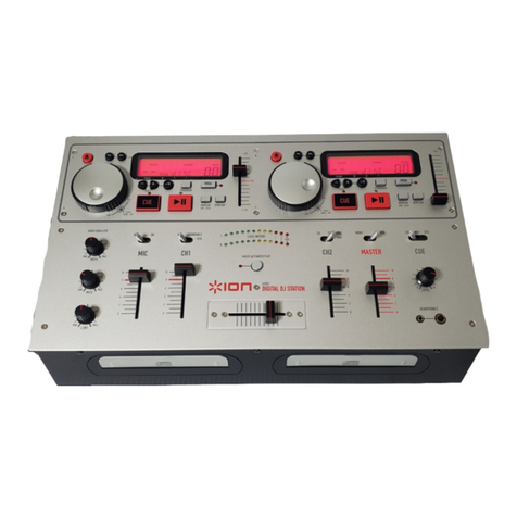
ION iCUE User manual

Confidential ION Audio Service Manual
ION Audio
iCUE
[iCUE]
Service Manual
v1.0
2012.07.24
The information in this document contains privileged and confidential information. It is intended
only for the use of those authorized by ION Audio. If you are not the authorized, intended
recipient, you are hereby notified that any review, dissemination, distribution or duplication of this
document is strictly prohibited. If you are not authorized, please contact ION Audio and destroy
Copyright ION Audio
ATTENTION!
THIS DOCUMENT CONTAINS SENSITIVE
PROPRIETARY INFORMATION.
ALL RECIPIENTS MUST HAVE A CURRENT
NON-DISCLOSURE AGREEMENT ON FILE
WITH ION AUDIO.
DO NOT MAKE ILLEGAL
COPIES OF THIS DOCUMENT

Confidential ION Audio Service Manual
PREFACE
This document is intended to assist the service technician in the operation, maintenance and
repair of the ION Audio device. Together with the User Reference Manual, this document
provides a complete description of the functionality and serviceability of the Device. Any
comments or suggestions you may have pertaining to the document are welcome and
encouraged.
READ THIS!
In addition to any purchase price that ION Audio may charge as consideration for ION Audio
selling or otherwise transferring this service manual (“Manual”) to you, if you are not a service and
repair facility (“Service Center”) authorized by ION Audio in writing to be an authorized Service
Center, ION Audio sells or transfers the Manual to you on the following terms and conditions:
Only Service Centers authorized by ION Audio in writing are authorized to perform service and
repairs covered by an ION Audio warranty (if any), and transfer of the Manual to you does not
authorize you to be an authorized Service Center. Therefore, if you perform, or if the Manual
is used to perform, any service or repairs on any ION Audio product or part thereof, any
and all warranties of ION Audio as to that product and any service contract with ION Audio
for that product shall be voided and shall no longer apply for such product, even if your
services or repairs were done in accordance with the Manual.
All service or repairs done by you or with reference to the Manual shall be solely your
responsibility, and ION Audio shall have no liability for any such repairs or service work. All such
service or repairs are performed at the sole risk of the person performing the service or
repairs. You agree that all such work will be performed in a competent, professional and safe
manner at all times and to indemnify and fully hold ION Audio and its successors and assigns
harmless in the event of any failure to so perform.
Your purchase of the Manual shall be for your own ultimate use and shall not be for purposes of
resale or other transfer.
As the owner of the copyright to the Manual, ION Audio does not give you the right to copy the
Manual, and you agree not to copy the Manual without the written authorization of ION Audio.
ION Audio has no obligation to provide to you any correction of, or supplement to, the Manual, or
any new or superseding version thereof.
ION Audio shall have the right to refuse to sell or otherwise transfer repair parts or materials to
you in its sole discretion. You shall not use, sell or otherwise transfer spare or replacement parts
supplied by ION Audio to you (i) to repair or be used in products manufactured for or by third
parties or (ii) to any third parties for any purpose.
You shall not make any warranties or guarantees with respect to the products of ION Audio or the
use thereof on behalf of ION Audio or in your own name.
The foregoing describes the entire understanding related to sale or transfer of the Manual to you,
and no other terms shall apply unless in a writing signed by an authorized representative of ION
Audio.
All Trademarks are property of their respective companies.

Confidential ION Audio Service Manual
WARNINGS
TO REDUCE THE RISK OF ELECTRIC SHOCK OR FIRE, DO NOT EXPOSE
THIS PRODUCT TO WATER OR MOISTURE.
The arrowhead symbol on a lightning flash inside a triangle is
intended to alert the user to the presence of uninsulated "dangerous
voltage" within the enclosed product which may be of sufficient
magnitude to constitute a risk of electric shock to persons.
The exclamation point inside a triangle is intended to alert the user
to the presence of important operating, maintenance and servicing
instructions in the literature which accompanies the product.
REPAIR BY ANY PERSON OR ENTITY OTHER THAN AN AUTHORIZED ION
AUDIO SERVICE CENTER WILL VOID THE ION AUDIO WARRANTY.
PROVISION OF THIS MANUAL DOES NOT AUTHORIZE THE RECIPIENT TO
COMPETE WITH ANY ION AUDIO DISTRIBUTOR OR AUTHORIZED REPAIR
SERVICE CENTER IN THE PROVISION OF REPAIR SERVICES OR TO BE
OR MAKE REPAIRS AS AN AUTHORIZED SERVICE CENTER.
ALL REPAIRS DONE BY ANY ENTITY OTHER THAN AN AUTHORIZED ION
AUDIO SERVICE CENTER SHALL BE SOLELY THE RESPONSIBILITY OF
THAT ENTITY, AND ION AUDIO SHALL HAVE NO LIABILITY TO THAT
ENTITY OR TO ANY OTHER PARTY FOR ANY REPAIRS BY THAT ENTITY.
Regarding the Power Supply Fuse
CAUTION: The product under service may employ the use of a
replaceable fuse. Danger of fire or electrocution if fuse is incorrectly
replaced. Replace with only the same type or equivalent type
recommended by the equipment manufacturer.
Regarding the Internal Battery
CAUTION: The product under service may employ the use of a
internal battery. Danger of explosion if battery is incorrectly
replaced. Replace only with the same or equivalent type
recommended by the manufacturer. Dispose of used batteries
according to the manufacturer's instruction.

Confidential ION Audio Service Manual
Safety Instructions
Carefully read the applicable items of the operating instructions and these safety suggestions
before using this product. Use extra care to follow the warnings written on the product itself and in
the operating instructions. Keep the operating instructions and safety suggestions for reference in
the future.
1. Power Source. The product should only be connected to a power supply which is described
either in the operating instructions or in markings on the product.
2. Power Cord Protection. AC power supply cords should be placed such that no one is likely to
step on the cords and such that nothing will be placed on or against them.
3. Periods of Non-use. If the product is not used for any significant period of time, the product's
AC power supply cord should be unplugged from the AC outlet.
4. Foreign Objects and Liquids. Take care not to allow liquids to spill or objects to fall into any
openings of the product.
5. Water or Moisture. The product should not be used near any water or in moisture.
6. Heat. Do not place the product near heat sources such as stoves, heat registers, radiators or
other heat producing equipment.
7. Ventilation. When installing the product, make sure that the product has adequate
ventilation. Improperly ventilating the product may cause overheating, which may damage the
product.
8. Mounting. The product should only be used with a rack which the manufacturer
recommends. The combination of the product and rack should be moved carefully. Quick
movements, excessive force or uneven surfaces may overturn the combination which may
damage the product and rack combination.
9. Cleaning. The product should only be cleaned as the manufacturer recommends.
10. Service. The user should only attempt the limited service or upkeep specifically described in
the operating instructions for the user. For any other service required, the product should be
taken to an authorized service center as described in the operating instructions.
11. Damage to the Product. Qualified service personnel should service the unit in certain
situations including without limitation when:
a. Liquid has spilled or objects have fallen into the product,
b. The product is exposed to water or excessive moisture,
c. The AC power supply plug or cord is damaged,
d. The product shows an inappropriate change in performance or does not operate
normally, or
e. The enclosure of the product has been damaged.

Confidential ION Audio Service Manual
This product shares the
design of Numark's
Total Control [KC0].

SPECIFICATION
FUNCTION
1. Scratch Whrrld……………………………..Works for setting cue point and scratching only.
2. LOOP………………………………………automatically loops a given time (like Pioneer safety loops).
3. Treble/Middle Bass…………………………EQ control. Push function of knob allows instant frequency kill.
4. Crossfader…………………………………..mixes between channels.
5. Parameter Knob……………………………..assignable to adjust effects. Has push function for added control.
6. SYNC………………………………………..Forces BPM alignment to opposing deck.
7. Tempo Slider………………………………...permanently sets speed (BPM).
8. Tempo Bend…………………………………momentarily adjusts speed.
9. KEY…………………………………………Locks key to natural recorded key (Master Tempo).
SERVICE MANUAL
MODEL:TOTAL CONTROL

DISASSEMBLY PROCEDURES
(A) REMOVE 8 PCS OF SCREW TO DISCONNECT FRONT PANEL AND REAR PANEL.
(A)
(B)
(C)
Fig.1
2.
(A). REMOVE 6 PCS OF SCREW TO DISCONNECT BOTTOM CHASSIS.
(A)
Fig.2

DISASSEMBLY PROCEDURES
(A) REMOVE 5 PCS OF VR KNOB.
(B) REMOVE 1 PC OF NAME PLATE.
(
C
)
REMOVE 6 PCS OF SCREW FROM PITCH FADER AND CROSS FADER.
(D) DISCONNECT 3 PCS OF CONNECTOR TO REMOVE PITCH FADER PCB AND CROSS FADER PCB
.
Fig.3
DISASSEMBLY PROCEDURES
(A) REMOVE 3 PCS OF SCREW FROM POWER PCB.
(B) DISCONNECT 2 PCS OF CONNECTOR TO REMOVE POWER PCB.
(C) REMOVE 4 PCS OF SCREW FROM SENSOR PCB.
(D) DISCONNECT 2 PCS OF CONNECTOR TO REMOVE SENSOR PCB.
(E) REMOVE 4 PCS OF SCREW FROM LINE FADER PCB.
(F) DISCONNECT 2 PCS OF CONNECTOR TO REMOVE LINE FADER PCB.
Fig.4

DISASSEMBLY PROCEDURES
(A) REMOVE 18 PCS OF SCREW FROM MAIN PCB.
(B) DISCONNECT 3 PCS OF CONNECTOR TO REMOVE MAIN PCB.
Fig.5


LEVEL
P/N DESCRIPTION QTY REF
1BAPS-W006 KNOB 1 27
1BAW-0973-Y-01-N WASHER 2 2
1CA040218002 USB CABLE 1
1CB300WMAR11 CD SLEEVE 1
1CB300WMAR12 CD SLEEVE 1
1CN0420000803 4P CONNECTOR (80mm) 5 34
1CN0520001003 5P CONNECTOR (100mm) 1 36
1CN1420001701 14P CONNECTOR (170mm) 1 37
1CN1425401002 14P CONNECTOR (100mm) 1 35
1ERE73 E RING 3MM 2 12
1LA62GMN37 DATE LABEL 1 33
1LAC22MAR204 SEARAL NO. LABEL 1 32
1LAC22MAR237 BAR CODE LABEL 1
1LAC22MAR238 BAR CODE LABEL 1
1LAC62MAR205 BAR CODE LABEL 1
1LAC62MAR219 BAR CODE LABEL 2
1LAC67MAR240 REV LABEL 1
1LAC67YAH261 LABEL 1
1MT0605502 BRASS 2 3
1MT1104436 FIXED METAL 1 20
1MT1104447 HOLDER PLATE 1 25
1NM1104406 VELVET CARPET 5 5
1NP211MAR19 NAME PLATE 1 19
1NP211MAR63 STAND SASH 1
1PT061073701 ADJUST TABLE PAINTING 2 1
1PT071068101 ROTATE 1 22
1PT1104446 FIXED HOLDER (SPINDLE) 1 28
1PT110445101 FIXED HOLDER PAINTING 1 40
1PT111067502 VR KNOB(BIG) PAINTING 5 21
1PT111068402 KNOB PRINTING 10 14
1PT1110685 KNOB 21 16
1PT111068701 KNOB 8 24
1PT111069501 ROTATE KNOB PAINTING 3 23
1PT111069901 KNOB PRINTING 8
1PT112040401 FRONT PANEL PAINTING PRINTING 1 38
1PT112040501 REAR PANEL PRINTING 1 26
1PT113000901 DECORATION WICKER PAINTING 2 4
1PT113030401 BOTTOM CHASSIS 1 29
1RU1130706 RUBBER STAND 2 30
1SC0208RABI SCREW 6 10
1SC0305RBNI SCREW 6 8
1SC0308FBNI SCREW 16 9
1SC0308RBNI SCREW 29 41
1SC0315FINI SCREW 6 18
1SPSA11930606W2 ADAPTOR 1
1TSKC0-1
CD
1
1TSKC0-2
CUE Sofeware CD
1
1WS113004503P WASHER 2 11
1 TWPC06C00901 POWER PCB ASS'Y 1 31
2AL2-51-0140 DIODE MBRS140LT3 1 D19
2AL2-61-7223 IC NJU7223DL1-33 3.3V TO-252 1 U17
2CS104Z2505Y5V CERAMIC 0.1UF (SMD) 11 C36~39,41~46,R1
2DIENLL4148SM DIODE ENLL4148SM (SMD) 1 D1
2DIZDS1GSM DIODE 1 D20
2EC22616TS ELECT 22UF/16V (S) 1 C40
2EC47550TS ELECT 4.7UF/50V (S) 1 C48
KC0MAR01 BOM

2JK0SCU201RFNO USB CONNECTOR 1 J15
2JKDJ-0702B-020 DC CONNECTOR 1 J16
2JW5206T JUMP WIRE 6 JMP1~4,7,8
2PC06C009 POWER PCB 1 -
2RS00018J05 RESISTOR 0(SMD) 1 R23
2RS10218J05 RESISTOR 1K (SMD) 1 R24
2RS10318J05 RESISTOR 10K (SMD) 2 R35,85
2RS51118J05 RESISTOR 510(SMD) 1 R25
2TE622000501 5P CONNECTOR 1 (J5)
2TE952541401 14P CONNECTOR 1 (J1)
2UHDLW5BTN501SQ2 CHOKE COIL 1 L1
1 TWPC06C01101 MAIN PCB ASS'Y 1
2 TWPC06C011A01 MAIN PCB ASS'Y 1 15
3AL0-09-0044 VR 2.5KB 8 P1,2,5,6,11~14
3AL0-17-0101 RESISTOR ARRAY 4X1005 R32,38,49~51
3AL2-50-4149 DIODE IN4148 SOT-23 38 D1~38
3AL2-73-4051 IC74HC4051 SINGLE 8-CHAN MUX 1 4 U1~4
3AL7-20-0075 CHOKE COIL 2.2UH 1 L2
3CS102J5005NPO CERAMIC 1000P (SMD) 4 C45~47,56
3CS103K5005X7R CERAMIC 0.01UF (SMD) 4 C65,66,76,85
3CS104K5005X7R CERAMIC 0.1UF (SMD) 69 C9~44,48~55,57~64,67,69~71,75,77~80,82,84,86~91
3CS200J5005COG CERAMIC 20P (SMD) 2 C68,72
3EC22616TS ELECT 22UF/16V (S) 3 C3,7,8
3EC47550TS ELECT 4.7UF/50V (S) 4 C2,6,73,74
3ICSN74AC373DWR IC SN74AC373DWR 5 U6~10
3ICYHFRC85 IC YHFRC85 (AL2-70-34220) 1 U5
4AL2-70-3422 IC MPU UPSD3422EVB-40U6 8032W/ 1 -
3LD-305SYV ORANGE LED 49 LED1~49
3MT070446701 IRON PLATE 1 (E1)
3PT01104803 LED FIXED 4.8X3MM 49 (LED1~49)
3RS00018J05 RESISTOR 0(SMD) 4 R18~20,27
3RS10118J05 RESISTOR 100(SMD) 18 R14,21,25,35,37,39,45,46,48,60,61,67~72,76
3RS10318J05 RESISTOR 10K (SMD) 11 R7,31,42,58,63,66,73,83,85,93,99
3 RS10418J05 RESISTOR 100K (SMD) 5 R40,41,47,54,55
3RS10518J05 RESISTOR 1M (SMD) 4 R1,4,15,34
3RS22018J05 RESISTOR 22(SMD) 3 R33,52,53
3 RS24118J05 RESISTOR 240(SMD) 29 R2,3,5,6,8~13,16,17,23,24,28~30,36,43,44,56,57,59,62,64
,65,74,75,87
3RS39118J05 RESISTOR 390(SMD) 20 R77~82,84,86,88~92,94,97,98,100~103
3RU0604401 RUBBER 2 (LED25,26)
3SWDC11B2021431 SWITCH 1 E1
3SWSKHVBB3420 SWITCH 4.3 31 S1~31
3TE10200502 5P CONNECTOR 1 (J9)
3TE612000402 4P CONNECTOR 4 (J6,7,10,11)
3TE612001401 14P CONNECTOR 1 (J12)
3TE962541401 14P CONNECTOR 1 (J5)
3UH11-2012-102T BEAD (SMD) 2 L1,3
3VRR10301701 VR 10KB 5 P3,4,7,10,17
3VRR10302004 VR 10KB 6 P8,9,15,16,18,19
3XTM40000X4 CRYSTAL OSCILLATOR 40MHz 1 Y1
2 TWPC06C011B01 SENSOR PCB ASS'Y 1 7
3AL2-56-5592 TRANSIST0R 2SC5592 2 Q1,2
3DIRPI-352 SENSOR 2 SEN1,2
3RS10318J05 RESISTOR 10K (SMD) 2 R95,116
3RS22318J05 RESISTOR 22K (SMD) 2 R108,110
3RS33118J05 RESISTOR 330(SMD) 2 R109,111
3RS56118J05 RESISTOR 560(SMD) 2 R104,105
3TE622000401 4P CONNECTOR 1 (J1)

2TWPC06C011C01 SENSOR PCB ASS'Y 1 17
3AL2-56-5592 TRANSIST0R 2SC5592 2 Q3,4
3DIRPI-352 SENSOR 2 SEN3,4
3RS10318J05 RESISTOR 10K (SMD) 2 R96,117
3RS22318J05 RESISTOR 22K (SMD) 2 R113,115
3RS33118J05 RESISTOR 330(SMD) 2 R112,114
3RS56118J05 RESISTOR 560(SMD) 2 R106,107
3TE622000401 4P CONNECTOR 1 (J2)
2TWPC06C011D01 PITCH PCB ASS'Y 1 6
3TE622000401 4P CONNECTOR 1 (J3)
3VRS10304508 VR 10KB 1 P20
2 TWPC06C011E01 PITCH PCB ASS'Y 1
3TE622000401 4P CONNECTOR 1 (J4)
3VRS10304508 VR 10KB 1 P21
1TWPC06C01602 LINE FADER PCB ASS'Y 1
2TWPC06C016A02 LINE FADER PCB ASS'Y 1 39
3CS104Z2505Y5V CERAMIC 0.1UF (SMD) 3 C8,89,90
3EC22616TS ELECT 22UF/16V (S) 1 C3
3JW5206T JUMP WIRE 5 JMP6,9,12,16,21
3RS10018J05 RESISTOR 10(SMD) 1 R34
3TE622000401 4P CONNECTOR 1 (J2)
3TE622001401 14P CONNECTOR 1 (J1)
3VRS10304508 VR 10KB 2 R97,99
2 TWPC06C016C01 CROSS FADER PCB ASS'Y 1 13
3CS104Z2505Y5V CERAMIC 0.1UF (SMD) 2 C9,87
3TE622000401 4P CONNECTOR 1 (J3)
3VRS10304509 VR 10KB 1 R100

MBRS140LT3
MBRS140LT3


A
Other manuals for iCUE
2
Table of contents
Other ION Dj Equipment manuals

ION
ION iDJ2GO User manual

ION
ION iDJ User manual

ION
ION party starter User manual

ION
ION MOBILE DJ User manual

ION
ION QUICK PLAY FLASH User manual

ION
ION DISCOVER DJ User manual

ION
ION iCJ01 Technical document

ION
ION Holiday Party Plus User manual

ION
ION HOUSE PARTY User manual

ION
ION Total PA Glow 2 User manual