IOtech 655u User manual

Warranty Information
Your IOtech warranty is as stated on the product warranty card. You may contact IOtech by phone,
fax machine, or e-mail in regard to warranty-related issues.
Phone: (440) 439-4091, fax: (440) 439-4093, e-mail: sales@iotech.com
Limitation of Liability
IOtech cannot be held liable for any damages resulting from the use or misuse of this product.
Copyright, Trademark, and Licensing Notice
All IOtech documentation, software, and hardware are copyright with all rights reserved. No part of this product may be
copied, reproduced or transmitted by any mechanical, photographic, electronic, or other method without IOtech’s prior
written consent. IOtech product names are trademarked; other product names, as applicable, are trademarks of their
respective holders. All supplied IOtech software (including miscellaneous support files, drivers, and sample programs)
may only be used on one installation. You may make archival backup copies.
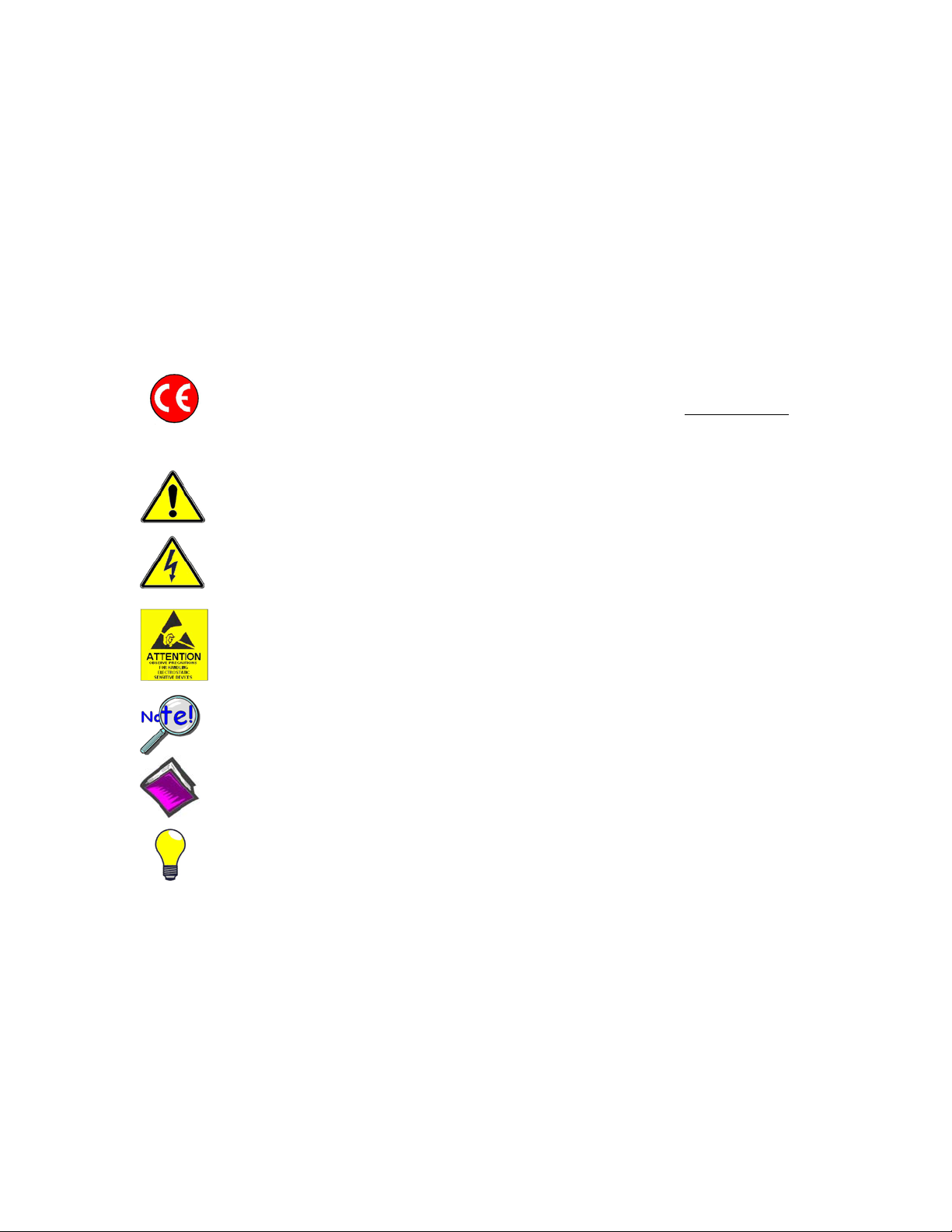
CE Notice
Many IOtech products carry the CE marker indicating they comply with the safety and emissions standards of the
European Community. When applicable these products have a Declaration of Conformity stating which specifications
and operating conditions apply. You can view our Declarations of Conformity at
Warnings, Cautions, Notes, and Tips
www.iotech.com/CE
Refer all service to qualified personnel. This caution symbol warns of possible personal injury or equipment damage
under noted conditions. Follow all safety standards of professional practice and the recommendations in this manual.
Using this equipment in ways other than described in this manual can present serious safety hazards or cause equipment
damage.
This warning symbol is used in this manual or on the equipment to warn of possible injury or death from electrical
shock under noted conditions.
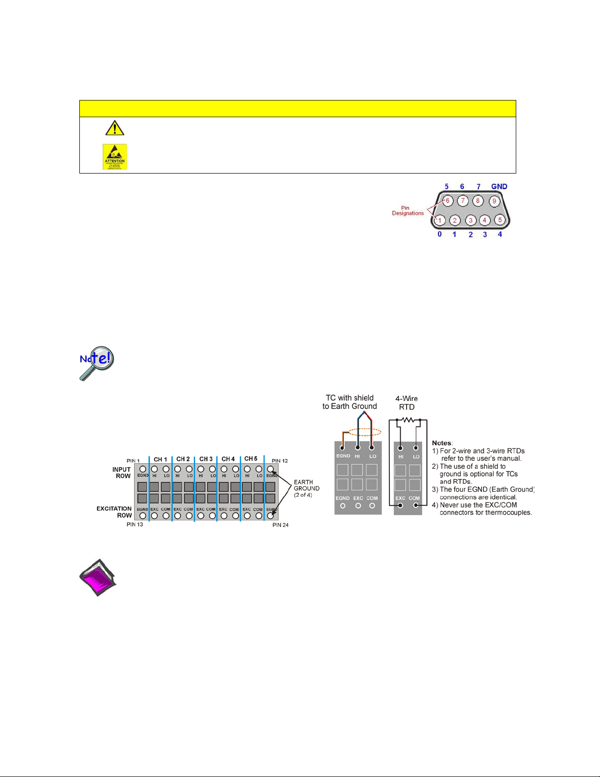
This ESD caution symbol urges proper handling of equipment or components sensitive to damage from electrostatic
discharge. Proper handling guidelines include the use of grounded anti-static mats and wrist straps, ESD-protective
bags and cartons, and related procedures.
This symbol indicates the message is important, but is not of a Warning or Caution category. These notes can be of
great benefit to the user, and should be read.
In this manual, the book symbol always precedes the words “Reference Note.” This type of note identifies the location
of additional information that may prove helpful. References may be made to other chapters or other documentation.
Tips provide advice that may save time during a procedure, or help to clarify an issue. Tips may include additional
reference.
Specifications and Calibration
Specifications are subject to change without notice. Significant changes will be addressed in an addendum or revision to
the manual. As applicable, IOtech calibrates its hardware to published specifications. Periodic hardware calibration is
not covered under the warranty and must be performed by qualified personnel as specified in this manual. Improper
calibration procedures may void the warranty.

IOtech 652u and 655u User’s Manual
CAUTION
Using this equipment in ways other than described in this manual can cause
personal injury or equipment damage. Before setting up and using your
equipment, you should read all documentation that covers your system.
Pay special attention to Warnings and Cautions.
Note:
During software installation, Adobe®PDF versions of user manuals will automatically
install onto your hard drive as a part of product support. The default location is in the
Programs group, which can be accessed from the Windows Desktop. Initial navigation
is as follows:
Start [on Desktop] Programs IOtech …
You can also access the PDF documents directly from the data acquisition CD by using
the <View PDFs> button located on the opening screen.
Refer to the PDF documentation for details regarding both hardware and software.

IOtech 652u and 655u User’s Manual 917891
Table of Contents
F
Quick Start, 652u and 655u
Chapter 1 –What are the 652u and 655u?
Chapter 2 –Block Diagram
Chapter 3 –Connectors, Indicators, and Cables
Front Panel (Analog) Connectors …… 3-1
Introduction …. 3-1
Analog Common …… 3-1
Current Source (IEPE) with Transducer Fault Detection ……. 3-1
Input Coupling …… 3-2
Anti-Aliasing …… 3-2
Analog Triggers …… 3-2
Rear Pannel Connectors and Indicators …… 3-2
External Power ……3-3
Digital I/O (requires eZ-TOMAS)…… 3-3
#6-32 Machine Screw (chassis to earth ground)…… 3-4
USB2.0 …… 3-4
LED Indicators …… 3-4
5 Channel TC / RTD Connector (655u only) …… 3-4
Chapter 4 –CE Compliance and Noise Considerations
Overview …… 4-1
CE Standards and Directives …… 4-1
Safety Conditions ……4-2
Emissions/Immunity Conditions …… 4-3
CE Rules of Thumb for 652u and 655u …… 4-3
Noise Considerations …… 4-4
Chapter 5 –Software Options for 600 Series Devices
eZ-Analyst …… 5-2
eZ-TOMAS …… 5-3
eZ-Balance …… 5-4
eZ-NDT …… 5-5*
Chapter 6 –Product Care and Customer Support
Electrostatic Discharge (ESD), Handling Notice…… 6-1
Product Care …… 6-1
ReadMe Files and the Install CD-ROM …… 6-2
Customer Support …… 6-2
Chapter 7.a –Specifications, IOtech 652u and 655u
7.b –Specifications, Data Plots
Appendix A –Changing the Device Name
*eZ-NDT does not support IOtech 652u or 655u.

1170-0940 rev 2.0 324996B-01
IOtech 652u and 655u Quick Start
10-Channel, USB2.0 Dynamic Signal Analyzers for Vibration Analysis & Monitoring
Before you get started verify that you have a 32-bit version of
Windows, the following items, and meet or exceed the minimum
requirements listed.
•IOtech 652u or 655u
•TR-2U Power Supply
•USB2.0 port [on PC] and USB Cable
•Dynamic Signal Analysis CD
•License Keys for purchased software;
e.g., eZ-Analyst, eZ-TOMAS
•Monitor: SVGA, 1024 x 768 screen resolution
•Windows 2000 SP4 and Windows XP users:
Intel™Pentium 4 or equivalent
1 GB memory; 10 GB disk space
•Windows Vista (x86) users:
PC must be Windows Vista Premium Ready
Step 1 - Install Software
1. Close all running applications on the host PC.
2. Insert the Dynamic Signal Analysis CD into your CD-ROM drive and wait for the CD to auto-run. An Opening Screen will
appear. As an alternative, you can download software from: www.iotech.com/ftp.html
3. Click the <ENTER SETUP> button.
Note: If you are downloading software from our website, follow instructions provided there.
4. From the hardware selection screen [which follows a licensing agreement], select the 652u or 655u from the drop-down list and
follow the on-screen instructions.
Step 2 - Connect the 652u [or 655u] to Power and to the Computer
Supply power from the TR-2U to the 652u [or 655u] before connecting the USB cable to the computer. This allows the
unit to inform the host computer (upon connection of the USB cable) that the hardware requires minimal power from the
computer’s USB port. When disconnecting a 652u [or 655u] from the PC, unplug the USB cable before unplugging the
TR-2U power cable.
1. Connect the TR-2U to a standard AC outlet.
2. Connect the TR-2U to the External Power connector on the 652u [or 655u].
3. Using a USB cable, connect the 652u [or 655u] to a USB2.0 port on the computer.
4. Follow the computer screen prompts as directed to allow the computer to detect your new hardware.
Note: The 655u rear panel includes a connector block
for 5 temperature channels, not shown.
652u or 655u [rear panel]

Printed in Hungary
LED Notes: The “Power” LED blinks during device detection and initialization; then remains on solid as long as the
module has power. If there is insufficient power the LED will go off.The “Active” LED is on whenever active
communication is taking place between 652u [or 655u] and the host PC. It will be on solid during data acquisitions.
Step 3 - Connect Data Acquisition Signal Lines
CAUTION
Turn off power to the system devices and externally connected equipment before connecting
cables. Electric shock or damage to equipment can result even under low-voltage conditions.
Take ESD precautions (packaging, proper handling, grounded wrist strap, etc.)
The 652u and 655u each have 10 analog channel inputs (CH1 through CH10) via
front panel BNC connectors and 8 digital I/O lines via rear panel DB9 connector.
In addition, the 655u has a removable block that provides a means of connecting
thermocouples and/or RTDs (5 total temperature channels, regardless of TC, RTD,
or mix).
Prior to making signal connections review the Specifications chapter of your 652u and 655u user’s manual to ensure that the
input signals do not exceed the specified limits. The manual is included in PDF format on the CD and covers both the 652u
and the 655u.
The following figures pertain to temperature channels and apply to the 655u only. The 652u cannot accept temperature
connections, nor can it measure temperature.
To ensure accurate temperature measurements allow the 655u to acclimate itself to ambient
temperature prior to acquiring data.
TC/RTD Connector Pinout (655u only) Wiring Schematics (655u only)
Reference Notes:
Adobe Acrobat PDF versions of documents pertaining to IOtech 652u and 655u are automatically installed onto
your PC’s hard-drive as a part of product support at the time of software installation. The default location is the
Programs group. It can be accessed via the Windows Desktop Start Menu.
IOtech
25971 Cannon Road, Cleveland, OH 44146-1833
E-mail: [email protected] Internet: www.iotech.com
*324996B-01*
324996B-01
Digital I/O Channel Designation
(outer numbers)

IOtech 652u and 655u User’s Manual 917291 What are the IOtech 652u and 655u? 1-1
What are the IOtech 652u and 655u? 1
IOtech 652u Front and Rear Panels
IOtech 655u Front and Rear Panels
IOtech 652u and 655u are dynamic signal analyzers used for monitoring and analyzing machinery and structures in
regard to sound, vibration, and rotation. In addition, the 655u includes a block on the right-side of the rear panel
for connecting up to five temperature channels via thermocouples and/or RTDs.
For both the 652u and 655u, the device hardware is the signal conditioning and acquisition engine, while the
software defines the specific analysis and monitoring features of the system. Since the software [in the host PC]
determines which capabilities will be used, it is easy to upgrade the system and add more capabilities over time.
Basic profile:
Model
Inter-
face
Temper-
ature
Channels
Analog
Input
Channels
High Pass
Filter
Cutoff
Analog
Input
Range
Analog
Output
Channels
Digital I/O
Channels
External
Power
Connector
652u
USB2.0
0
10
0.1 Hz
±40 V
0
8
6 to 16 VDC
1 amp (max.)
655u
USB2.0
5
10
0.1 Hz
±40 V
0
8
6 to 16 VDC
1 amp (max.)
The IOtech 652u and 655u each include a high-speed USB2.0 engine. The USB interface allows all acquired data
to be transferred to the PC in real time at 1.05 Meg samples/sec. This means that every acquired data point can
reside on the host PC’s hard drive, making re-creation and post acquisition analysis of acquired data as precise as
possible. The 652u, 655u (and also our 640e, 640u, 650e, and 650u) transmit all time-domain measurements. This
means there is no data loss when analyzing acquired waveforms. Since the data is already on the host PC’s hard
drive there is no time lost transferring data.
The 652u / 655u architecture is such that there is virtually no limit to the length of time continuous data can be
acquired. The only limitation is the amount of available hard disk memory on the host PC, or that which can be
accessed by a PC on a network.

1-2 What are the IOtech 652u and 655u? 917891 IOtech 652u and 655u User’s Manual
Features of the Dynamic Signal Inputs
o a current source for transducer biasing (IEPE)
o detection of a transducer fault
o AC coupling: 0.1 Hz; or DC coupling
o ±40 V range
o anti-aliasing filters: 3-pole low pass filter in hardware;
software FIR filters are automatically set for each analysis rate
o pseudo-differential inputs
o support for TEDS (Transducer Electronic Data Sheet) in eZ-Analyst
o any analog input channel can serve as a tach input
o tight channel-to-channel phase matching
USB2.0 ready:Easy Connection to USB2.0-ready Notebooks, Desktop PCs, or USB2.0 Hubs.
Note that the USB2.0 port allows a continuous stream of data to be collected and stored in the host PC.
Analog Input Channels:10 BNC connectors
Temperature Measurement Channels (655u only): 5 channels, thermocouple or RTD. Wiring
connects to 655u rear panel via a removable connector block.
8 Digital I/O Channels: DB9 connector for connection of Digital I/O signal lines.
Note: eZ-NDT or eZ-TOMAS software must be used to make use of the Digital I/O.
Analog Channel Triggering
Pre- and Post-Trigger Readings
Reference Notes:
For information regarding 655u connections for temperature measurement, refer to chapter 3.
For information regarding software, refer to chapter 5.

IOtech 652u and 655u User’s Manual 878091 Block Diagram 2-1
Block Diagram 2
IOtech 652u and 655u Block Diagram
** See page 2-2 for temperature channel block diagram.

2-2 Block Diagram 878091 IOtech 652u and 655u User’s Manual
This temperature channel block diagram applies only to the 655u. The 5 channel TC / RTD removable
connector connects to the rear panel of the 655u.
Temperature Channel Block Diagram (655u only)
*The gray block for temperature channel 1 (TEMP. CH 1) is also representative of the remaining four
temperature channels.

IOtech 652u and 655u User’s Manual 878091 Block Diagram 2-3
General Comments
The following short descriptions are provided to supplement the block diagrams presented on pages 2-1 and 2-2.
For additional information refer to Chapter 3, Connectors, Indicators, and Cables.
USB2.0
The IOtech 652u and 655u transfer acquired data to the PC via a USB2.0 connection. It is important
to note that USB ports and USB hubs cannot supply sufficient power to 652u or 655u.
Power
Power (6 to 16VDC at 400mA) is typically supplied by a TR-2U power adapter connected to the
External Power Jack. An equivalent source of DC power can be used in place of a TR-2U.
LEDs
Active
The Active LED is on whenever active communication is taking place between the
652u [or 655u] and the host PC. Note that the Active LED will be on solid during a data
acquisition.
Power
The “Power” LED blinks during device detection and initialization; then remains on solid
as long as the module has power. If there is insufficient power the LED will go off.
Digital
I/O
To make use of the Digital I/O feature the 652u [or 655u] must be operating with eZ-TOMAS or
eZ-NDT. The 8-bits of digital I/O are provided via a rear panel DB9 connector. Each bit is
programmable as input or output.
BNCs
Up to ten BNC connectors, designated as Channels 1 through 10, can be used to connect analog input
signals to the 652u [or 655u]. The BNC center-conductor is the signal HI and the BNC shell is the
signal LO.
5 Channel
TC / RTD
Removable
Connector
(Applies to the 655u only) The 5 channel TC / RTD removable connector connects to the rear panel of
the 655u. The connector can be used to connect up to five temperature measurement channels. Each
channel can use a thermocouple or an RTD.
Chapter 3 includes a connector pinout and wiring diagrams
•Thermocouple
for the following:
•TD 4-wire
•RTD 3-wire
•RTD-2 wire
Note: Earth grounds are available for shielded sensors.

652u & 655u User’s Manual 989490 Connectors, Indicators, and Cables 3-1
Connectors, Indicators, and Cables 3
Front Panel (Analog) Connectors …… 3-1
Introduction …. 3-1
Analog Common …… 3-1
Current Source (IEPE) with Transducer Fault Detection ……. 3-1
Input Coupling …… 3-2
Anti-Aliasing …… 3-2
Analog Triggers …… 3-2
Rear Pannel Connectors and Indicators …… 3-3
External Power ……3-3
Digital I/O (requires eZ-TOMAS)…… 3-3
#6-32 Machine Screw (chassis to earth ground)…… 3-4
USB2.0 …… 3-4
LED Indicators …… 3-4
5 Channel TC / RTD Connector (655u only) …… 3-4
Front Panel (Analog) Connectors
Front Panel – Aside from the model number, the 652u and 655u front panels look the same
Introduction
The front panel includes ten BNC connectors for voltage input. These are labeled CH1 through CH10. The front
panel also includes analog common.The IOtech 652u and 655u include circuitry for dynamic analog signal
conditioning. The circuitry typically interfaces with piezoelectric transducers that include, but are not limited to:
accelerometers, microphones, and force/pressure transducers; and non-piezoelectric transducers such as
tachometers and proximity probes.
Features of 652u and 655u dynamic signal conditioning circuits include:
ocurrent source for transducer biasing (IEPE)
odetection of a transducer fault
oAC or DC coupling
o±40 V range
oanti-aliasing filters: 3-pole low pass filter in hardware; programmable digital filtering via software
opseudo-differential inputs
osupport for TEDS (Transducer Electronic Data Sheet), requires eZ-Analyst
oany analog input channel can serve as a tach input
otight channel-to-channel phase matching
osignal parameters are independently controlled in software on a per channel basis
Analog Common
The BNC shells for the analog input channels have a 1k ohm resistance from the BNC shell to analog ground. The
BNC center-conductor is the signal HI and the BNC shell is the signal LO. Each BNC shell is connected to the
chassis ground through its own channel-dedicated 1 kΩresistor. Consequently, the shell is not meant to be driven
more than ±8V from earth ground to BNC shell.
If the host computer is a desktop PC, then the computer ground will likely connect to the AC power line ground.
If the host computer is a notebook PC, then the computer ground could be: (a) floating, for example, when operating
on batteries, or (b) connected to a vehicle ground, for example, when using an automotive cigarette lighter adapter in
conjunction with the vehicle’s battery.
TIP: Additional measurement noise may be present when using earth grounded transducers.
For best results electrically isolate the input transducers from earth ground.

3-2 Connectors, Indicators, and Cables 989490 652u & 655u Users Manual
Current Source (IEPE) with Transducer Fault Detection
Note: IEPE current source can only be enabled when AC Coupling is selected.
If IEPE is selected in software, a constant current is supplied to bias IEPE transducers. The bias current is sourced
through the center conductor of the input channel BNC connector and returns to the conditioning circuit by the outer
conductor. The current source features a voltage operating compliance and is short-circuit and over-voltage
protected as stated in the specifications. Operating compliance refers to the highest voltage that can be sourced
without change of the current source value. In the absence of a transducer, the current source will output a higher
open circuit voltage. For unused channels and for other applications that do not require bias, the current
source should be disabled from the input via software control, on a per channel basis.
When the current source is enabled, the input voltage is continuously monitored with level detection circuitry for
indicating an open transducer (high voltage) or a transducer short (low voltage). Existence of either condition
triggers a transducer fault for the associated channel. This error is communicated to the user on the monitor via
software and is also available through a software status request at the end of an acquisition. Faults are detected and
communicated when present. Detection of a fault does not alter the acquisition process or its data.
Input Coupling
The analog input channels can be independently set in software to AC Coupling or to DC Coupling. When AC
Coupling is selected, the input signal passes through a high pass filter. When DC Coupling is selected the high-pass
filter is bypassed.
Anti-Aliasing
The 652u and 655u analyzers each include three-pole anti-aliasing filters and 24-bit sigma/delta analog-to-digital
converters (ADC). The converters exhibit an alias frequency band between 1.69MHz and 6.75MHz, which eases
the requirements of the anti-aliasing filters. Transducers seldom have significant energy at these high frequencies.
However, should there happen to be such energy, the filters will attenuate it. Refer to the specifications chapter for
details, including a response chart.
Analog Triggers
The IOtech 652u and 655u signal analyzers can be triggered per software configuration relevant to the 10 analog
input channels. Refer to the associated software documentation regarding the various types of triggers and how to
set them.
Reference Notes:
For detailed information, refer to the applicable software document, i.e., eZ-TOMAS or eZ-Analyst.
PDF versions of the documents can be accessed via the <View PDFs> button on the Dynamic Signal
Analysis (DSA) CD’s opening screen.
In addition to software documentation, information regarding aliasing, anti-aliasing, sensors,
accelerometers, sound and vibration, and transducers may prove useful to your application. The
internet is a great source for this material.
In regard to TEDS (Transducer Electronic Data Sheet), you may find the IEEE 1451 standard to be of
interest.

652u & 655u User’s Manual 989490 Connectors, Indicators, and Cables 3-3
Rear Panel Connectors and Indicators
IOtech 652u Rear Panel, Partial View
IOtech 655u 5 Channel TC / RTD Connector
Note: For Connector Shell Information see page 3-6.
The rear panels of both the 652u and 655u include, from left to right: an External Power connector, DB9-Digital I/O port,
USB2.0 connector, a #6-32 chassis ground, and two status LEDs (ACTIVE and POWER). In addition, the rear panel of the
655u includes a 24 pin removable block connector that provides a means of connecting up to 5 thermocouples, RTDs, or a
combination of the two. The connection block is located just to the right of the LEDs. Pinouts and schematics are provided
at the end of this chapter.
EXT POWER
oInput voltage to TR-2U: 90-264 VAC
: +6 to +16 VDC, 1 amp (maximum). Power is typically supplied from a TR-2U power adapter.
The TR-2U is an AC-to-DC conversion power supply with the following ratings:
oTR-2U voltage output (supply to 652u, or 655u): typically 9VDC
oMax Current Output: 1.7 amp; but will typically output 400mA to meet
the 652u’s [or 655u’s] relatively small power demand.
DIGITAL I/O (Note: requires eZ-TOMAS installed on the host PC)
Eight digital I/O lines are accessible via a 9-pin, female DSub connector. Each bit of digital I/O can be programmed
individually to be either an input or an output. By hardware default, the digital I/O port boots up as an input. This is
to prevent any 652u [or 655u] digital output from possibly damaging external hardware.
Digital I/O Connector
DB9 –on rear panel
The digital I/O can be read synchronously or asynchronously. It can also be read asynchronously while being in a
synchronous acquisition. Synchronously, the digital I/O will be read at the same rate as the analog channels, and
thus can be read as fast as 105.469 kHz. Since all of the analog signals are read simultaneously along with the digital
I/O channel in synchronous mode, there is no delay between any analog signal and the digital I/O channel.
Asynchronously, the digital I/O can be either read or written to, as opposed to the synchronous mode, which is read-
only.
Points to note:
•To use the 652u or 655u Digital I/O, the host PC must have eZ-TOMAS software installed.
•All configurations pertaining to Digital I/O are controlled by software and can be updated by the
software at any time.
•All 8 digital inputs can be read back as part of the scan group of an acquisition.
Digital I/O
Channel
Numbers

3-4 Connectors, Indicators, and Cables 989490 652u & 655u Users Manual
Reference Note:
For detailed documentation regarding software and Digital I/O you will need to refer to the
eZ-TOMAS User’s Manual. A PDF version is included on the DSA CD.
#6-32 machine screw (chassis to earth ground):
The machine screw on the rear panel is used to connect the chassis to solid earth ground. It can also be used to connect
transducer shields.
USB2.0
oIOtech 652u and 655u require connection to USB2.0
:This port is intended for USB2.0 high-speed (480Mbps). In regard to 652u [or 655u], connection to a USB2.0
port on the host PC is required. The use of a High-Speed USB Cable is recommended. IOtech cable part numbers CA-179-
1, -3, and -5 are 1m, 3m, and 5m in length, respectively.
The IOtech 652u and 655u both transfer acquired data to the PC via USB. When a computer has a board with USB 2.0
ports, an “Enhanced” USB controller can be found in the Device Manager. The Device Manager will also show two other
USB controllers due to the fact that USB2.0 circuitry includes 3 chips [one for the actual USB2.0 capable devices and two
for backward USB1.1 compatibility]. Thus a USB 2.0 motherboard can host any USB device (version 2.0 or lower),
assuming there are no defects with the board, system, and/or device.
oUSB 1.1 (obsolete) hubs will work on USB 2.0 ports, but cannot utilize USB 2.0 capabilities.
oHi-Speed and Full/Low-Speed USB devices can coexist on USB 2.0 hubs.
oUSB 2.0 hubs can be used on computers with USB 1.1 ports, but will not exhibit USB 2.0 capabilities.
oMinimize hub use and keep USB cables as short as possible.
oUSB ports and USB hubs cannot supply sufficient power to a 652u, or 655u.
LED Indicators
ACTIVE This indicator is on whenever active communication is taking place between the 652u [or 655u] and
the host PC. Note that the ACTIVE LED is on solid during data acquisitions.
POWER This indicator blinks during device detection and initialization; and then remains on solid, as long
as there is sufficient power. If there is insufficient power the POWER LED will go off.
5 Channel TC / RTD Connector (655u only)
The rear panel of the 655u includes a removable block connector that provides a means of connecting up to five
thermocouples, or five RTDs, or a combination of TCs and RTDs, not to exceed five.

652u & 655u User’s Manual 989490 Connectors, Indicators, and Cables 3-5
The following diagram is applicable to 655u only. The 652u cannot accept temperature connections.
The 5-channel connector block is of the “tension clamp” type. To insert a wire, complete the following steps:
1) Ensure the wire is in the 28 gauge to 16 gauge range. 5-22AWG is optimum.
2) Strip all wire to clear 7mm of insulation from the connector-end.
6) Repeat the above five steps to make additional wire connections.
Note: For each scenario you can connect shielding. When using shielding, connect it to one of the four earth grounds.
The earth ground pins are 1, 12, 13, and 24. See diagram on page 3-4.
Note:After completing connections, install the temperature connector shell as discussed on the next page.
3) Insert a 7mm flathead screwdriver into the square opening (by the associated contact) to
release the clamp tension.
4) Insert the stripped wire into the designated contact, according to the
applicable scenario.
5) Remove the screwdriver to re-engage the
tension clamp; then check your connection to
ensure the wire is clamped in place.
3
4
5

3-6 Connectors, Indicators, and Cables 989490 652u & 655u Users Manual
Installing the Temperature Connector Shell
1. Insert tie-wrap through two slots in the
shell-base. Note that you can use two
different slots for the tie-wrap if you
want your wires to extend through the
side of the connector instead of through
the rear, as illustrated.
2. Place the wire/TC connector assembly
onto the shell-base.
Secure the wires with the tie-wrap.
3. Place the hole-plate in the grooves on the
side of the shell-base. If the wires passed
through this opening you would place the
hole-plate at the other opening.
Place the shell-hood over the lower
assembly. It will snap into place.
4. Connect the TC connector to the TC
connection receptacle on the rear panel
of the 655u.
Tie-wrap
Shell-base
TC wires
TC Connector
Shell-base
Hole-plate
Shell-hood
Connect to 655u

652u and 655u User’s Manual 987690 CE-Compliance & Noise Considerations 4-1
CE Compliance & Noise Considerations 4
Overview ……4-1
CE Standards and Directives …… 4-1
Safety Conditions ……4-2
Emissions/Immunity Conditions ……4-3
CE Rules of Thumb for 652u and 655u …… 4-3
Noise Considerations …… 4-4
Overview
CE compliant products bear the “CE” mark and include a Declaration of Conformity stating the
particular specifications and conditions that apply. The test records and supporting documentation
that validate the compliance are kept on file at the factory.
This product meets the essential requirements of applicable European directives, as amended for
CE markings in accordance with the product family standard for:
•electrical equipment for measurement, control, and laboratory use
•immunity requirements for equipment used in controlled EM environments
Refer to this product’s Declaration of Conformity (DoC) for any additional regulatory compliance
information. To obtain the DoC for this product, visit
CE Standards and Directives
iotech.com/CE
The electromagnetic compatibility (EMC) directives specify two basic requirements:
1. The device must not interfere with radio or telecommunications.
2. The device must be immune from electromagnetic interference from RF transmitters, etc.
The standards are published in the Official Journal of European Union under direction of CENELEC
(European Committee for Electrotechnical Standardization). The specific standards relevant to data
acquisition equipment are listed on the product’s Declaration of Conformity.
The safety standard that applies to data acquisition products is EN 61010-1 : 1993 (Safety Requirements
for Electrical Equipment for Measurement, Control, and Laboratory Use, Part 1: General Requirements).
Environmental conditions include the following:
•indoor use
•altitude up to 2000 m
•temperature 5°C to 40°C (41°F to 104°F)
•maximum relative humidity 80% for temperatures up to 31°C (87.8°F) decreasing linearly
to 50% relative humidity at 40°C (104°F)
•mains supply voltage fluctuations not to exceed ±10% of the nominal voltage
•other supply voltage fluctuations as stated by the manufacturer
•transient overvoltage according to installation categories (overvoltage categories) I, II and III
For mains supply, the minimum and normal category is II
•pollution degree I or II in accordance with IEC 664

4-2 CE-Compliance & Noise Considerations 917891 652u and 655u User’s Manual
For clarification, terms used in some Declarations of Conformity include:
pollution degree: any addition of foreign matter, solid, liquid or gaseous (ionized gases) that may
produce a reduction of dielectric strength or surface resistivity. Pollution Degree I has no influence
on safety and implies: the equipment is at operating temperature with non-condensing humidity
conditions; no conductive particles are permitted in the atmosphere; warm-up time is sufficient to
avert any condensation or frost; no hazardous voltages are applied until completion of the warm-up
period. Pollution Degree II implies the expectation of occasional condensation.
overvoltage (installation) category: classification with limits for transient overvoltage, dependent
on the nominal line voltage to earth. Category I implies signals without high transient values.
Category II applies to typical mains power lines with some transients.
Safety Conditions
Users must comply with all relevant safety conditions as stated in the user’s manual and in the pertinent
Declarations of Conformity. Both the documentation and the associated hardware make use of the
following Warning and Caution symbols. If you see any of these symbols on a product or in a document,
carefully read the related information and be alert to the possibility of personal injury and/or equipment
damage.
This WARNING symbol is used in documentation and/or on hardware to warn of
possible injury or death from electrical shock under noted conditions.
This WARNING/CAUTION symbol is used to warn of possible personal injury or
equipment damage under noted conditions.
This CAUTION symbol warns of possible equipment damage due to electrostatic
discharge. The discharge of static electricity can damage some electronic
components. Semiconductor devices are especially susceptible to ESD damage. You
should always handle components carefully, and you should never touch connector
pins or circuit components unless you are following ESD guidelines in an appropriate
ESD-controlled area. Such guidelines include the use of properly grounded mats and
wrist straps, ESD bags and cartons, and related procedures.
Unless otherwise stated our data acquisition products contain no user-serviceable
parts. Only qualified personnel are to provide service to the devices.
The specific safety conditions for CE compliance vary by product; but general safety conditions include the
following bulleted items:
The operator must observe all safety cautions and operating conditions specified in the
documentation for all hardware used.
The host computer and all connected equipment must be CE compliant.
All power must be off to the device and externally connected equipment before internal access to the
device is permitted.
Isolation voltage ratings: do not exceed documented voltage limits for power and signal inputs.
All wire insulation and terminal blocks in the system must be rated for the isolation voltage in use.
Voltages above 30 Vrms or ±60 VDC must not be applied if any condensation has formed on the
device.
Current and power use must not exceed specifications. Do not defeat fuses or other over-current
protection.

652u and 655u User’s Manual 917891 CE-Compliance & Noise Considerations 4-3
Emissions/Immunity Conditions
The specific immunity conditions for CE compliance vary by product; but general immunity conditions
include:
Cables must be shielded, braid-type with metal-shelled connectors. Input terminal connections are to
be made with shielded wire. The shield should be connected to the chassis ground with the hardware
provided.
The host computer must be properly grounded.
In low-level analog applications some inaccuracy is to be expected when I/O leads are exposed to
RF fields or transients over 3 or 10 V/m as noted on the Declaration of Conformity.
CE Rules of Thumb for 652u and 655u
IOtech 652u and 655u are CE Compliant at the time they leave the factory and should remain in compliance
as long as the conditions stated on the Declaration of Conformity continue to be met.
A few general rules of thumb:
Use short cables.
When possible use shielded cables.
When assembling or disassembling components, take ESD precautions,
including the use of grounded wrist straps.
Ensure that the host computer is CE Compliant.
Review the most recent Declaration of Conformity for your 652u and/or 655u .
Ensure all system components are properly grounded.
This manual suits for next models
1
Table of contents
Other IOtech Measuring Instrument manuals