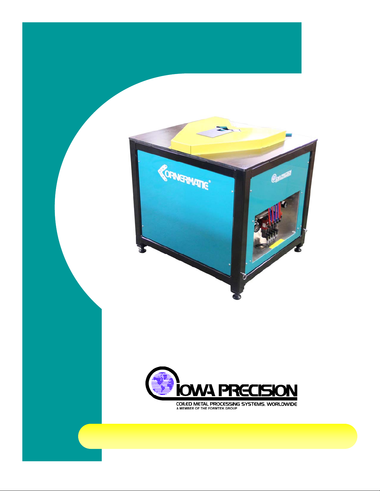
Iowa Precision Cornermatic Plus User manual

IPI003V04
CORNERMATIC PLUS
H. WEISS MACHINERY & SUPPLY
PHONE: (718) 605-0395 - www.hweiss.com

H. WEISS MACHINERY & SUPPLY
PHONE: (718) 605-0395 - www.hweiss.com

i
CORNERMATIC PLUS
TABLE OF CONTENTS
TABLE OF CONTENTS
SAFETY SUMMARY
LOCKOUT GUIDE
ELECTRICAL SCHEMATIC (Back of Manual)
ASSEMBLY DRAWINGS (Back of Manual) Section/Page
1. INSTALLATION.........................................................................................................................1-1
A. SELECTING A LOCATION............................................................................................................... 1-1
B. PNEUMATIC REQUIREMENTS ....................................................................................................... 1-1
C. ELECTRICAL REQUIREMENTS...................................................................................................... 1-1
D. RECEIVING AND UNPACKING THE EQUIPMENT......................................................................... 1-1
E. SAFETY REQUIREMENTS............................................................................................................... 1-2
(1) Safety Precautions before Starting the Machine..........................................................1-2
(2) Safety Precautions When Operating the Machine.......................................................1-2
2. SYSTEM OVERVIEW................................................................................................................2-1
(1) Flange & Corner Requirements...................................................................................2-2
(2) Duct Requirements......................................................................................................2-2
B. TABLE TOP COMPONETS.............................................................................................................. 2-3
C. PNEUMATIC CONTROL PANEL ..................................................................................................... 2-3
(1) Pressure settings.........................................................................................................2-4
(2) Secondary Pressure Setting........................................................................................2-4
D. PROGRAMMABLE LOGIC CONTROL (PLC) OPERATING SEQUENCE ..................................... 2-4
E. CONTROLS....................................................................................................................................... 2-5
(1) POWER OFF...............................................................................................................2-5
(2) POWER ON.................................................................................................................2-5
(3) MAGAZINE LOW.........................................................................................................2-5
(4) Control Sequence........................................................................................................2-5
3. SYSTEM OPERATION..............................................................................................................3-1
A. SAFETY PRECAUTIONS ................................................................................................................. 3-1
(1) Before Starting the Machine ........................................................................................3-1
(2) When Operating The Machine.....................................................................................3-1
B. LOADING CORNERS ....................................................................................................................... 3-2
C. ADDING NEW CORNERS................................................................................................................ 3-3
D. PREPARATION FOR OPERATION.................................................................................................. 3-4
E. SYSTEM SHUT-DOWN..................................................................................................................... 3-4
4. MAINTENANCE.........................................................................................................................4-1
A. TORQUE VALUES FOR GENERAL ASSEMBLY ........................................................................... 4-1
H. WEISS MACHINERY & SUPPLY
PHONE: (718) 605-0395 - www.hweiss.com

ii
CORNERMATIC PLUS
B. MAINTENANCE SAFETY..................................................................................................................4-4
C. SERVICING........................................................................................................................................4-4
(1) Lubrication, General Requirements .............................................................................4-4
(a) Lubrication Schedule................................................................................................4-4
D. PREVENTIVE MAINTENANCE.........................................................................................................4-4
(1) Preventive maintenance checks: .................................................................................4-5
E. TROUBLESHOOTING.......................................................................................................................4-5
F. ASSEMBLY DRAWINGS & ELECTRICAL SCHEMATICS..............................................................4-7
LIST OF TABLES
Table 4-1. Metric Bolt And Cap Screw Torque Values..........................................................4-2
Table 4-2. Unified Inch Bolt And Cap Screw Torque Values.................................................4-3
Table 4-3. Troubleshooting Chart..........................................................................................4-6
LIST OF FIGURES AND ILLUSTRATIONS
Figure 2-1 Cornermatic Plus .................................................................................................2-1
Figure 2-2 TDC and TDF Duct Fitting Flange Requirements................................................2-2
Figure 2-3 Fitting Height Minimum........................................................................................2-2
Figure 2-4 Table Top Components .......................................................................................2-3
Figure 2-5 Pneumatic Manifold Assembly.............................................................................2-4
Figure 2-6 Control Panel Switches........................................................................................2-5
Figure 2-7 Bottom Head Cycle Start Levers..........................................................................2-6
Figure 2-8 PLC Press & Crimp Timer Adjust Potentiometers (Under Cover)........................2-6
Figure 3-1 Pre-packaged Corners.........................................................................................3-2
Figure 3-2 Presser Cover......................................................................................................3-2
Figure 3-3 Inserting Corners .................................................................................................3-3
Figure 3-4 Duct fittings Placement........................................................................................3-4
Figure 4-1 Electrical Symbols Used On Assembly Drawings (Sheet 1 of 2).........................4-8
H. WEISS MACHINERY & SUPPLY
PHONE: (718) 605-0395 - www.hweiss.com

a
CORNERMATIC PLUS
SAFETY SUMMARY
INTRODUCTION
Safety is everyone’s business... Whether you are an equipment operator, a maintenance
person, a supervisor, or business owner, you are directly responsible for the day-to-day safe
operation of the equipment under your control. It is your responsibility to maintain and
operate this equipment in strict compliance with all applicable laws, safety regulations, and
the manufacturer’s recommended procedures.
PROMOTING SAFETY
Institute a company safety program. Management has a moral and legal responsibility for
promoting industrial safety. The formation of an organized safety program is strongly
recommended. This safety program should include the formation of a safety committee to
review and update company safety policies on a regular basis. Establish a firm policy on
safety regulations in the work place. Publish these objectives, spelling out each employee’s
responsibilities. Make certain that each employee knows what is expected of them.
SAFETY PROGRAM
The following steps are suggestions that a company developing, or expanding, a
comprehensive safety program should consider:
1. Industrial equipment manufacturers carefully design safeguards into their product in order
to minimize hazards. However, the manner in which equipment is incorporated into a
manufacturing process may inadvertently create a hazard or otherwise defeat built-in
safeguards. Closely examine the operation of your company’s processing equipment.
Take notice of potential hazards. Install guards or take other appropriate action to
eliminate hazard risks.
2. Make certain equipment operators and maintenance personnel are properly trained.
3. Setup a program of daily, weekly, and monthly machinery inspection. Make a check list.
Keep a historical record of all maintenance work, repairs, and adjustments.
4. Frequently evaluate safety guards and devices during actual product runs. Correct any
unsafe practice or situation immediately.
5. Establish safe, convenient material handling systems. If conveyor equipment is installed
in your facility, it should conform to recommendations published in the ‘American National
Standard, Conveyors and Related Equipment, Safety Standards for ANSI/ASME B20.1’
which is available from the American National Standards Institute (ANSI).
6. Provide personal protective equipment, such as safety glasses with side shields, safety
helmets, tongs, gloves, hand pads, spats, and protective sleeves, as required to suit the
operation.
7. Organize a company safety committee. Schedule periodic meetings on a regular basis to
review and update all safety policies.
8. Establish a firm policy on safety regulations in the work place. Publish these objectives,
spelling out each employee’s responsibilities. Make certain that each employee knows
what is expected of them.
9. Investigate all accidents and close calls. Take immediate action to prevent a recurrence
of the incident. Keep records of the investigation and the corrective measures taken.
H. WEISS MACHINERY & SUPPLY
PHONE: (718) 605-0395 - www.hweiss.com

b
CORNERMATIC PLUS
10. Post a list of names, addresses, and phone numbers of physicians and others who are to
be called in emergency situations.
CUSTOMER'S RESPONSIBILITIES
There are certain hazards associated with the operation of any equipment or system of
machinery that are impractical, if not impossible, for equipment suppliers to safeguard. The
user must address these hazards and be responsible for providing guards or barriers for
establishing appropriate work procedures and for training personnel in the safe operation of
that equipment.
With respect to coil and strip processing equipment, the following hazards should be noted:
•Open pits and depressions or raised areas in the floor.
•Space between machines, where strip edges and ends are exposed during feed-up,
run, and tail-out conditions. This includes carry-over tables and both roller and belt
conveyors.
•Nip and pinch points of machinery, coils, and strip which may be exposed in feed-up,
run, and tail-out.
•Areas surrounding coil handling devices where coils are in motion, such as coil cars,
conveyors, up-enders and turnstiles.
•Areas surrounding payoff reels and re-coilers, where clock-springing strip ends
present a hazard during banding, un-banding, feed-up and tail-out conditions.
•Sheet and pack handling devices (including conveyors) where the motion, as well as
shifting of sheets or packs, may present a hazard.
•The area surrounding sheet stacking devices, which must be approached for setup,
but which should be clear of personnel during operation because of moving
machinery or material.
•Areas associated with high temperatures, high pressure fluids (hydraulic, air, or
water) and electrical devices and connections.
•The vicinity of machinery which moves into or out of the line.
REFERENCE SOURCES
Questions concerning specific hazards or safeguarding of equipment may be addressed to
the equipment manufacturer. For additional information, refer to the sources listed here:
American National Standards Institute (ANSI)
ANSI B11.18, ”Machinery and Machine Systems for the Processing of Coiled Strip,
Sheet and Plate - Safety Requirements for Construction, Care and Use.” ANSI
B11.4, “Shears: Safety Requirements for Construction, Care and Use.” ANSI
B11.14, ”Coil-Slitting Machines/Systems Safety Requirements for Construction, Care
and Use.” ANSI B11.18, ”Machinery and Machine Systems for the Processing of
Coiled Strip, Sheet and Plate - Safety Requirements for Construction, Care and Use.”
National Fire Protection Association (NFPA)
NFPA 79, “Electrical Standards for Industrial Machinery.”
European Union
“Directives on Safety of Machinery” and “CE Marking”
H. WEISS MACHINERY & SUPPLY
PHONE: (718) 605-0395 - www.hweiss.com

c
CORNERMATIC PLUS
WARNING LABELS
Warning and safety related informational labels are placed on the Iowa Precision Industries’
equipment at strategic points. It is important that these labels are not removed, covered,
hidden, or defaced. The purpose of these labels is to alert personnel to potential personal
injury hazards or other direct or indirect safety concerns.
DANGER indicates an imminently hazardous situation which, if not
avoided, will result in death or serious injury.
WARNING indicates a potentially hazardous situation which, if not
avoided, could result in minor or serious injury.
CAUTION indicates a potentially hazardous situation which, if not
avoided, may result in minor or moderate injury.
NOTICE indicates a company policy that relates directly or indirectly
to the safety of personnel or protection of property.
“It is important that the meaning of a safety sign is clearly understood
by those who may come in contact with the hazard. To increase the understanding of a safety sign’s
components, the ANSI Z535 committee encourages safety sign manufacturers and owners of
facilities to publish and exhibit the following (above) information on safety posters, safety bulletins or
the like. Doing so will assist in the objective of achieving a national uniform system for the
recognition of potential personal injury hazards and accident prevention.” - ANSI Z535.2, Annex A1
H. WEISS MACHINERY & SUPPLY
PHONE: (718) 605-0395 - www.hweiss.com

d
CORNERMATIC PLUS
WARNING MESSAGES IN THIS MANUAL
Throughout this manual various DANGER, WARNING, CAUTION, and safety
related NOTICE messages appear. The intent is to alert operator and maintenance
personnel to potential hazards. In addition, important operation and maintenance details are
emphasized with the NOTE heading.
SAFETY FIRST
The equipment in this line was designed and manufactured for a specific task. DO NOT use
the equipment for any other function or to process material that is beyond the equipment’s
design specifications. Modifications or additions to this equipment line should not be made
without first consulting MESTEK MACHINERY. Replacement and maintenance parts should
be equal to original equipment. Use of other parts may result in unsafe operating conditions.
If there is a question as to the suitability of a part, MESTEK MACHINERY should be
consulted.
In general, every piece of equipment must be treated as dangerous. While operating or
maintaining this equipment, each person must be aware of their own safety as well as the
safety of all others around the line.
Material Coils
Coils present numerous hazards. They may shift, roll or fall without warning. Some
coils may spring open without warning. Sharp edges of the strip in the coil are
hazardous. Stay clear of coils as they are being moved. Use extreme caution any
time a coil is approached or handled.
Metal Strips
The metal strip may have sharp or ragged edges. The strip is under tension and is
subject to abrupt tension changes. This can result in strip breakage with the ends
flying without warning. Stay clear of the strip whenever possible. When it is necessary
to approach or handle the strip, use extreme caution. Use protective devices such as
tongs, gloves, eye protection, and wrist guards as required for safety. The strip
presents many pinch hazards with the machinery. Stay clear of these. Never step on
or over strip in the line.
Machinery
Never reach into any piece of machinery which is operating or which is capable of
operation. Loose clothing or jewelry should be kept clear of machinery at all times.
When working on one piece of equipment, be aware of hazards of surrounding
equipment. Any item inserted into a machine may be thrown or may cause a
dangerous malfunction or breakage.
Safe Guards
No equipment should be operated unless the safe guards or devices supplied with
the product fittings are securely in place and properly adjusted.
H. WEISS MACHINERY & SUPPLY
PHONE: (718) 605-0395 - www.hweiss.com

e
CORNERMATIC PLUS
WARNING
MESTEK MACHINERY has conduct hazard evaluation and risk analysis studies for their
product. Safe guards installed on the equipment are there for a reason. BEFORE
EQUIPMENT IS PLACED INTO SERVICE, ALL SAFE GUARDS OR DEVICES MUST BE IN
PLACE AND PROPERLY ADJUSTED.
Maintenance
Before performing any maintenance on a piece of equipment, insure that all power is
locked off in accordance with your company’s lockout/tagout policy. Be sure that all
movable members (such as rolls, arms, tables, etc.) are securely blocked from
inadvertent motion which might be hazardous. Treat all electrical lines as being live
and all Mestek Machinery as being under high pressure. Ensure that all items are
properly reassembled before placing them into operation. Before equipment is
returned to service, ALL safe guards or devices MUST BE in place and properly
adjusted.
NOTICE
Before doing any WELDING ON EQUIPMENT, the following precautions must
be taken to insure against damage:
1) All power is removed from system.
2) The weld ground is connected to the closest possible location on the unit
where the welding is being performed.
3) All encoders, sense eyes, and controls should be electronically
disconnected if at all possible to avoid possible damage.
Operation
This equipment is capable of speeds, tensions, and adjustments which may be
hazardous for some of the materials within the line specification. For example, thin,
narrow strip may be subjected to tensions sufficient to cause breakage. Never
attempt to process any material unless the safe adjustments for that particular are
known and can be implemented.
Traffic Around Equipment
Care should be taken at all times in moving around the equipment, whether on foot or
in a vehicle. Changes in floor elevation, machine bases and debris around the
equipment are trip hazards. Take care that personnel are not trapped between
vehicles and equipment.
WARNING
Do not attempt to walk or climb on any machine while in operation. Failure to observe this
warning may result in death or serious injury.
HAZARD REMINDER
Use the following HAZARD REMINDER sheet to reinforce awareness of the hazards
associated with coil processing lines. This reminder can be a useful supplement to your
company’s safety program. MESTEK MACHINERY suggests the following steps:
H. WEISS MACHINERY & SUPPLY
PHONE: (718) 605-0395 - www.hweiss.com

f
CORNERMATIC PLUS
1. SHOW each individual the HAZARD REMINDER sheet and explain each category of
hazard.
2. POINT OUT EXAMPLES of each type of hazard on the actual equipment the individual
operates or works around.
3. EXPLAIN HOW TO AVOID HAZARDS in the individuals work environment.
4. GIVE a copy of the HAZARD REMINDER sheet to each individual.
Safety is everyone’s business!
H. WEISS MACHINERY & SUPPLY
PHONE: (718) 605-0395 - www.hweiss.com

THINK SAFETY FIRST
NIP POINT
WHEN ONE OBJECT ROTATES NEAR ANOTHER, IT CAN PULL YOU
IN and CRUSH YOU
PINCH POINT
WHEN ONE OBJECT MOVES CLOSER TO ANOTHER, IT CAN CUT or PINCH
YOU.
MOVING EQUIPMENT and COILS
CAN KNOCK YOU OFF BALANCE or CRUSH YOU
STRIP EDGES and ENDS
CAN CUT or STRIKE YOU.
ELECTRICAL and FLUID SYSTEMS
CAN SHOCK and BURN YOU and CAN EXPLODE.
CLIMBING ON MACHINES
CAN MAKE YOU FALL - MAYBE INTO ONE OF THE HAZARDS ABOVE.
H. WEISS MACHINERY & SUPPLY
PHONE: (718) 605-0395 - www.hweiss.com

H. WEISS MACHINERY & SUPPLY
PHONE: (718) 605-0395 - www.hweiss.com

A
CORNERMATIC PLUS
LOCKOUT GUIDE
The protection of life and limb through responsible actions and adequate safeguards are the
responsibility of all individuals in a workplace environment, or any environment where action or miss-
action could possibly endanger the safety and wellbeing of others.
All maintenance, repair and adjustment procedures performed on this equipment shall comply with
existing established Lockout requirements. At a minimum, these requirements must include the use
of a keyed padlock or similar device utilized to physically and securely remove and isolate any
power source from the equipment, preventing accidental reapplication while personnel may be in
exposed circumstances, subject to possible injury or death.
These requirements must also include the tagging of the lockout device to notify all individuals
working in the area, or anyone who could for whatever reason be in a position to possibly remove or
otherwise defeat the purpose of the lockout device, as to its installation, why, and the individual
responsible for its application.
Power sources include electrical, pneumatic, hydraulic, or any other hazardous energy source. This
procedure shall be used to ensure that the machine is stopped and isolated from all potentially
hazardous energy sources and that these energy sources are locked out before employees perform
any servicing or maintenance when the unexpected energization, start-up of the machine, or the
release of stored energy could cause injury.
FOR THIS UNIT (where applicable)
•Hydraulic power sources are provided with a lockable valve to block hydraulic pressure
from the system. Where applicable, this valve shall be placed in the off position and locked in
place.
•Electrical power sources are provided either with a male plug for connection to the electrical
source, or are hardwired to the source distribution panel. When a plug is provided, the plug
shall be disconnected from the source power and secured within a covering and tagged
appropriately.
When hardwired to the source distribution panel, the panel shall have a manual disconnect
which is lockable in the off position, or in the event of a circuit breaker, the panel will have a
lockable door which will deny access to unauthorized personnel.
•Pneumatic power is applied to the machine through a quick disconnect fitting. This quick
disconnect fitting shall be disconnected from the pneumatic power source and secured within
a covering and tagged appropriately.
H. WEISS MACHINERY & SUPPLY
PHONE: (718) 605-0395 - www.hweiss.com

B
CORNERMATIC PLUS
H. WEISS MACHINERY & SUPPLY
PHONE: (718) 605-0395 - www.hweiss.com

Page 1-1
CORNERMATIC PLUS
Figure 1-1.Cornermatic
Plus
INSTALLATION
1. INSTALLATION
A. SELECTING A LOCATION
Select a location that will save the most work and time in
moving duct fittings about in your shop. A table that
matches the height of the bottom head base plate of the
Cornermatic Plus is a must in helping to position the duct
fittings sections into the Cornermatic Plus, especially if only
one person may be handling the duct fittings.
B. PNEUMATIC REQUIREMENTS
A clean, dry air supply of 11 CFM at 100 PSI (not to exceed
120 PSI) must be made available to the equipment. This
can be a rigid supply line such as pipe, but the terminating
line to the equipment should be a non-rigid air line to isolate
the compressor and machine from each other’s vibrations.
C. ELECTRICAL REQUIREMENTS
Electrical power requires only the availability of a standard 115 VAC (or optional 240 VAC)
three prong type grounded outlet to plug in the connector on the Cornermatic Plus. The
machine should also be located away from grinding machines, sanding machines, spray
painting areas, and other sources of contamination if at all practical. Answers to questions
regarding site preparation and other technical assistance is available by calling our Service
Department.
D. RECEIVING AND UNPACKING THE EQUIPMENT
When the equipment arrives, inspect it carefully before accepting the shipment. It is important
to note any damage on the Bill of Lading or other shipping documents so that a claim can be
filed with the carrier. Pay special attention to the control wiring, air regulator, gauges, etc.
Check for physical damage to the switches and the components inside the Cornermatic Plus.
If anything looks damaged, notify both the carrier (to file a claim) and the Service Department
at the factory (to order replacement parts). It is important to notify the factory promptly so the
new parts arrive before the machine is installed, as it may not be possible to start and run the
machine without them.
•Removing any covers, steel strapping, or packing around the machine.
•Set the Cornermatic Plus upright in a vertical position, preferably in its final product
location.
•Adjust the leveling foot pads to firmly rest on the foundation keeping the bottom head
base plate horizontally as level as possible.
•Make any final adjustments necessary with the leveling foot pads to make the bottom
head base plate level horizontally.
Before operating the Cornermatic Plus, read the safety section of this manual. Study and
follow the safety precautions in this section, which are intended to prevent injury to you and
H. WEISS MACHINERY & SUPPLY
PHONE: (718) 605-0395 - www.hweiss.com

Page 1-2
CORNERMATIC PLUS
your fellow workers. They cannot, however, cover all possible situations, therefore, consider
the consequences of your actions before executing any procedure or operation.
E. SAFETY REQUIREMENTS
Before operating the machine, read this section. Study and follow the safety precautions listed
here which is intended to prevent injury to you and your fellow workers. The precautions listed
cannot cover all possible situations. Therefore, consider the consequences of your actions
before executing any procedure or operation.
(1) Safety Precautions before Starting the Machine
1. Protect yourself. Wear safety glasses and leather gloves when handling metal. Do not
wear loose clothing, neckties, or jewelry. If long sleeves must be worn, avoid cuffs and
buttons.
2. Keep your work area clean. Remove all scrap, oil spills, rags, tools, and other loose
items that could cause you to slip, trip, and fall.
3. Make sure that the electrical supply and air pressures are at specified levels before
operating the machine.
4. Be sure that all guards are in place when operating the machine. Keep the equipment
properly maintained.
5. Be alert for loose, worn, or broken parts. Do not attempt to operate the machine with
such parts present, or if the machine is making unusual noises or actions.
6. Be sure this operation manual is kept near the machine so the operator can refer to it
when necessary. If you have not already done so, study the manual before operating
the machine.
7. Be aware of the location of the power off push-pull switch and use it to stop the
machine in case of emergencies.
(2) Safety Precautions When Operating the Machine
1. Be alert whenever operating the machine.
2. Only one person should control the machine. Never allow anyone to operate the
controls while you are working on the machine. Use "WORK" tags and warning signs
to indicate that someone is working on or repairing the machine.
3. Keep your arms and hands away from the internal workings of the machine when
starting or stopping the machine.
4. Never leave the work area while the machine is running.
5. Do not try to process material that is beyond the specified thickness or width for your
machine. Use good quality metal coils that are free from camber, burrs, and other
irregularities.
6. When cleaning the machine, or any components of the machine, do not use toxic or
flammable substances. Do not perform any cleaning operations while the machine is
running.
7. Never override or disable any safety switch or safety interlock.
8. Use proper size wrenches and tools, most of which are furnished with the machine.
Do not use adjustable crescent wrenches or worn wrenches. A slipping wrench can
cause injury. Replace worn nuts, bolts, screws, etc., being sure they are of equivalent
quality of those being replaced.
H. WEISS MACHINERY & SUPPLY
PHONE: (718) 605-0395 - www.hweiss.com

Page 2-1
CORNERMATIC PLUS
SYSTEM OVERVIEW
2. SYSTEM OVERVIEW
The Iowa Precision Industries Cornermatic Plus is a compact, pneumatically operated
machine that inserts TDC/F corners into duct fittings sections. Refer to Flange and Corner
Requirements section of this manual for corner specifications. The unit will automatically insert
a corner in a duct fittings corner and crimp it securely and permanently into place.
When a duct fitting with the TDC/F type end connector is manufactured, it is necessary to
install corner pieces into the corners of each end of the duct fittings. When the corner of the
end of the air duct fittings is positioned properly into the Cornermatic Plus head, the unit will
automatically begin the sequence required to insert a corner piece into the corner.
Figure 2-1 Cornermatic Plus
The duct fitting is first clamped into position on the bottom head by rigid clamps, then a corner
piece is slid into position on the inside edges of the bottom corner. The corner is then
immediately pressed into the flange corner and the corner piece is crimped securely into place
with the edges of the TDC/F flanges on the duct fittings.
The machine tooling retracts to its home positions making it ready for the next insert cycle to
be initiated. The operator removes the duct fitting, rotates the duct fitting to the next corner,
and repeats the procedure as required.
NOTE
A capacity label has been placed on the side of the Cornermatic Plus stating your machines
maximum gauge that can be fitted with corners. DO NOT attempt heavier gauge material than your
machines capacity or damage to the machine will occur and/or the factory warranty will be voided.
H. WEISS MACHINERY & SUPPLY
PHONE: (718) 605-0395 - www.hweiss.com

Page 2-2
CORNERMATIC PLUS
(1) Flange & Corner Requirements
The Cornermatic Plus is designed to insert TDF or TDC corners into ductwork. To ensure
the Cornermatic Plus operates as designed the TDF or TDC flange, corners and duct
fittings must meet specific criteria.
The width of the flange is shown below and must be maintained to ensure the corners are
pressed into the flange completely before the lip of the flange is crimped. Variations in
width will cause the corners to not seat completely or the corners may not be secured
properly.
Figure 2-2 TDC and TDF Duct Fitting Flange Requirements
The corners used in the Cornermatic Plus must also meet specific criteria. The only
corners guaranteed to work in the Cornermatic Plus are DuctMate corners or Mestek
Machinery Corners. Please contact Mestek Machinery for information on ordering
DuctMate or Mestek Machinery corners.
(2) Duct Requirements
To ensure proper corner insertion and crimping, the duct fitting must have a minimum 2
inch straight before the transition angle begins. This 2 inch straight is critical for heavier
gauges (16 or 18).
Also, critical for proper corner insertion and crimping is having proper lock seams.
Partially open or mismatched lock seams are just two of the common imperfections that
can cause problems inserting and crimping corners.
Proper maintenance, upkeep and adjustment of the duct making equipment are essential.
Please contact the Mestek Machinery service department regarding production of
ductwork.
Figure 2-3 Fitting Height Minimum
H. WEISS MACHINERY & SUPPLY
PHONE: (718) 605-0395 - www.hweiss.com

Page 2-3
CORNERMATIC PLUS
B. TABLE TOP COMPONETS
The Cornermatic Plus working platform is low profile, which helps with insertion of corners into
duct fittings of various configurations and sizes. The tooling of the Cornermatic Plus was
designed and manufactured for years of dependable production. The platform components
also require little or no adjustment.
Figure 2-4 Table Top Components
Item Description Item Description
A Corners D Start Levers
B Feeder E Crimpers
C Clamps F Guide Bars
C. PNEUMATIC CONTROL PANEL
Located on the side of the Cornermatic Plus is the pneumatic control panel. This panel
includes two air regulators and the pneumatic manifold with control valves.
Each valve has a manual override (J) which can be used for setup and maintenance. To utilize
the manual override, insert a small screwdriver into the slot and turn clockwise to activate or
counter clockwise to deactivate the valve.
H. WEISS MACHINERY & SUPPLY
PHONE: (718) 605-0395 - www.hweiss.com

Page 2-4
CORNERMATIC PLUS
Figure 2-5 Pneumatic Manifold Assembly
Item Description Item Description
A Incoming air supply gauge G Corner elevate valve
B Incoming air supply regulator H Corner elevate pressure regulator
C Lock valve I Corner elevate pressure gauge
D Feed valve J Secondary pressure regulator
E Press valve K Secondary pressure gauge
F Crimp valve L Valve manual override
(1) Pressure settings
The recommended pressure setting for the system pressure is 100 PSI (6.89 bar) and the
corner-elevate pressure setting is 40 PSI (2.70 bar). Refer to the pneumatic schematic for
additional information.
(2) Secondary Pressure Setting
This pressure regulator provides supplemental air to the magazine elevate function during
the time that the main air is turned off. This pressure is used, if required, to ensure the
corners are up in position before they are fed into the duct. If a corner is not up in position
the feed cylinder will not be able to push the corner into the duct.
Initially, the pressure should be set at zero. If, after time, the corners are not being raised
up into position to be fed into the duct, raise the pressure in increments of 3-5 PSI (.21-.34
bar). Adjust as needed.
D. PROGRAMMABLE LOGIC CONTROL (PLC) OPERATING SEQUENCE
The operating sequence of the Cornermatic Plus is controlled by a programmable logic control
(PLC) located within the electrical enclosure on the machine. The unit operates with a
standard 115 VAC (Optional 240 VAC) outlet circuit. Once the unit is plugged into a power
source, power is applied to the system and PLC by pressing the POWER ON push-button
H. WEISS MACHINERY & SUPPLY
PHONE: (718) 605-0395 - www.hweiss.com
Table of contents
Popular Industrial Equipment manuals by other brands

Cembre
Cembre PCM-2P/FC Operation and maintenance manual

Cassese
Cassese 910 JR owner's manual

HOWA MACHINERY
HOWA MACHINERY HH11C instruction manual

HEIDENHAIN
HEIDENHAIN QAN 200L Replacing Instructions

KTR-Group
KTR-Group KTR-STOP XS-A-F B Series Operating & assembly instructions

STEINEL
STEINEL ALC100 KNX-S operating instructions