IPico WN400-S User manual


IPico™ WN400 Integrated Access Device User Guide
User Guide © 2001 Lucid Voice 1
Table of Contents
________________________________
Introduction . . . . . . . . . . . . . . . . . . . . . . . . . . . . . . . . . . . . . . . . 1
Technical Support . . . . . . . . . . . . . . . . . . . . . . . . . . . . . . . . . . 2
Package Contents . . . . . . . . . . . . . . . . . . . . . . . . . . . . . . . . . . 3
Required Accessories . . . . . . . . . . . . . . . . . . . . . . . . . . . . . . . . 4
Quick Installation . . . . . . . . . . . . . . . . . . . . . . . . . . . . . . . . . . 5
Network Topology . . . . . . . . . . . . . . . . . . . . . . . . . . . . . . . . . . 6
Placing Calls . . . . . . . . . . . . . . . . . . . . . . . . . . . . . . . . . . . . . . . 7
Inter-site Telephony Connection . . . . . . . . . . . . . . . . . . . . . . 7
Setup . . . . . . . . . . . . . . . . . . . . . . . . . . . . . . . . . . . . . . . . . . . . 7
Placing a Call . . . . . . . . . . . . . . . . . . . . . . . . . . . . . . . . . . . . . . 8
Remote PBX Connection . . . . . . . . . . . . . . . . . . . . . . . . . . . . . 8
Setup . . . . . . . . . . . . . . . . . . . . . . . . . . . . . . . . . . . . . . . . . . . . 8
Placing a Call . . . . . . . . . . . . . . . . . . . . . . . . . . . . . . . . . . . . . . 9
Remote PSTN (Public Switched
Telephone Network) Connection . . . . . . . . . . . . . . . . . . . . 10
Setup . . . . . . . . . . . . . . . . . . . . . . . . . . . . . . . . . . . . . . . . . . . 10
Placing a Call . . . . . . . . . . . . . . . . . . . . . . . . . . . . . . . . . . . . . 10
Remote PBX Extension . . . . . . . . . . . . . . . . . . . . . . . . . . . . . . 11
Setup . . . . . . . . . . . . . . . . . . . . . . . . . . . . . . . . . . . . . . . . . . . 11
Placing a call . . . . . . . . . . . . . . . . . . . . . . . . . . . . . . . . . . . . . . 12

User Guide IPico™ WN400 Integrated Access Device
User Guide © 2001 Lucid Voice
2
Configuration . . . . . . . . . . . . . . . . . . . . . . . . . . . . . . . . . . . . . 12
Web Manager Configuration Tool . . . . . . . . . . . . . . . . . . . . 12
Accessing the unit . . . . . . . . . . . . . . . . . . . . . . . . . . . . . . . . . . 12
Parameters . . . . . . . . . . . . . . . . . . . . . . . . . . . . . . . . . . . . . . . . 13
COMmander Configuration Tool . . . . . . . . . . . . . . . . . . . . . 18
Specifications . . . . . . . . . . . . . . . . . . . . . . . . . . . . . . . . . . . . . 20
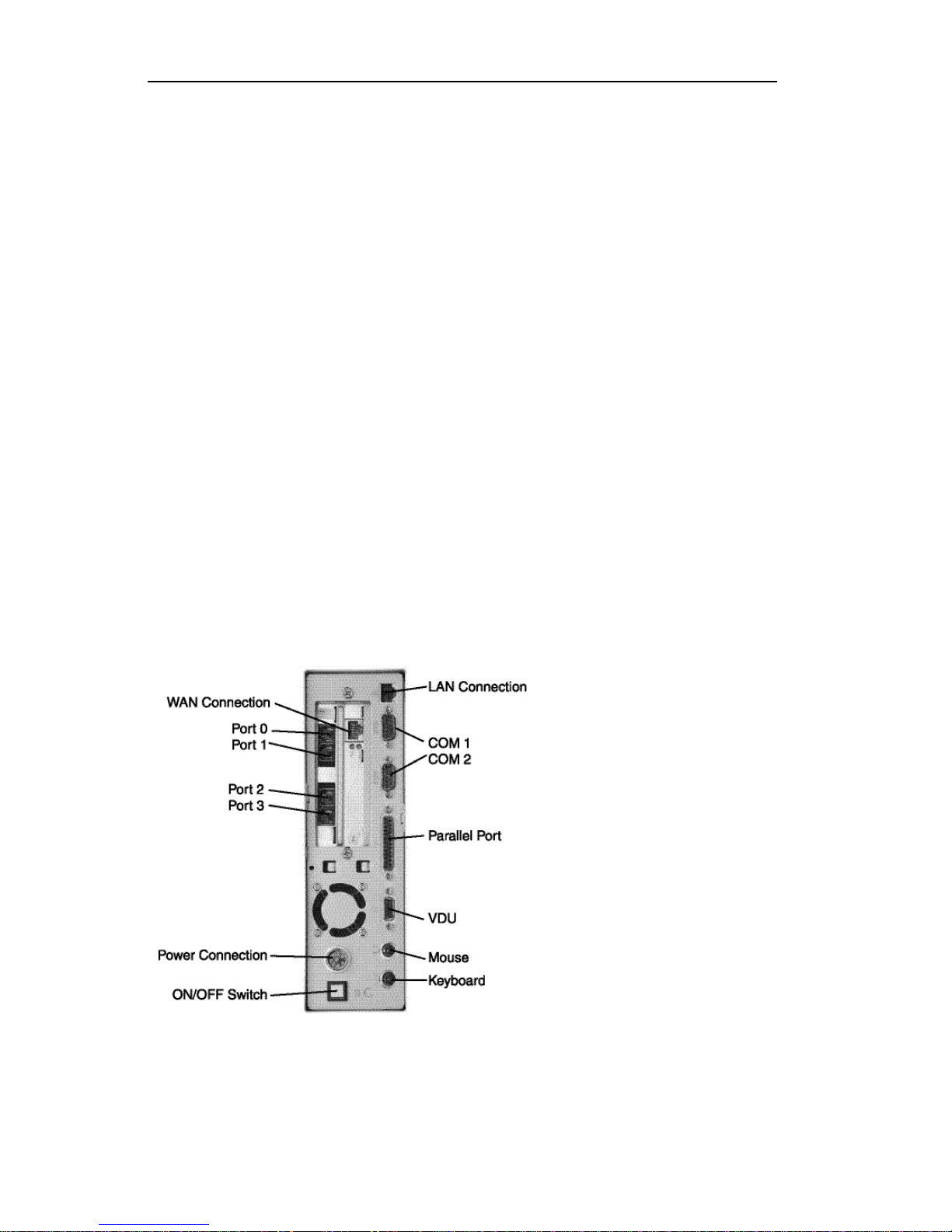
Indicators, Interfaces, and Controls . . . . . . . . . . . . . . . . . . . 20
Product Capabilities . . . . . . . . . . . . . . . . . . . . . . . . . . . . . . . . 20
Voice Support . . . . . . . . . . . . . . . . . . . . . . . . . . . . . . . . . . . . . 21
Management Features . . . . . . . . . . . . . . . . . . . . . . . . . . . . . 21
Security Features . . . . . . . . . . . . . . . . . . . . . . . . . . . . . . . . . . . 21
Interfaces . . . . . . . . . . . . . . . . . . . . . . . . . . . . . . . . . . . . . . . . . 21
Standards and Protocols Supported . . . . . . . . . . . . . . . . . . 22
Troubleshooting . . . . . . . . . . . . . . . . . . . . . . . . . . . . . . . . . . . 22
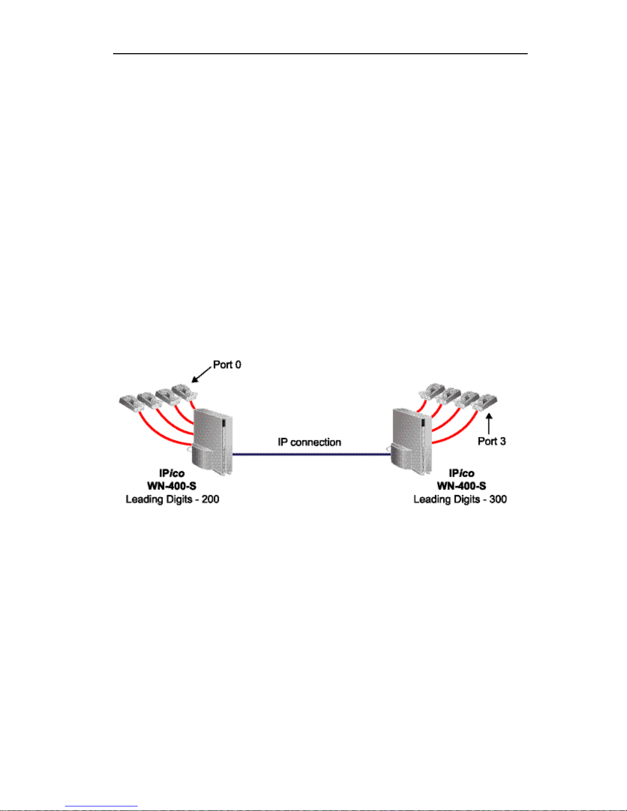
Dialing and Placing Calls . . . . . . . . . . . . . . . . . . . . . . . . . . . . 22
Using COMmander . . . . . . . . . . . . . . . . . . . . . . . . . . . . . . . . . 24
Using the Web Manager . . . . . . . . . . . . . . . . . . . . . . . . . . . . 24
Network Problems . . . . . . . . . . . . . . . . . . . . . . . . . . . . . . . . . . 25
Quality of Service (QoS) . . . . . . . . . . . . . . . . . . . . . . . . . . . . . 26
Error Messages . . . . . . . . . . . . . . . . . . . . . . . . . . . . . . . . . . . 27
Appendix A . . . . . . . . . . . . . . . . . . . . . . . . . . . . . . . . . . . . . . . . 29
Version Number . . . . . . . . . . . . . . . . . . . . . . . . . . . . . . . . . . . . 29
Factory Settings . . . . . . . . . . . . . . . . . . . . . . . . . . . . . . . . . . . . 29
Serial Parameters . . . . . . . . . . . . . . . . . . . . . . . . . . . . . . . . . . 29
Passwords . . . . . . . . . . . . . . . . . . . . . . . . . . . . . . . . . . . . . . . . . 29
Limited Warranty . . . . . . . . . . . . . . . . . . . . . . . . . . . . . . . . . . 30

IPico™ WN400 Integrated Access Device User Guide
User Guide © 2001 Lucid Voice 3
Introduction
Congratulations on your purchase of IPico™ WN400 Point-to-Point
system. The IPico is a complete, all-in-one voice and data Integrated
Access Device (IAD). IPico provides excellent, cost-effective voice over IP
(VoIP) and data integration for simultaneous telephony and data transfer
with Quality of Service (QoS) enforcement on a wide range of IP
networks. The state-of-the-art IPico technology allows voice and data
users to share bandwidth on a single wide area network (WAN) link.
Every telephone call is compressed and assigned a dedicated voice channel,
which is prioritized over the data channel. Because IPico prioritizes voice
over data, it guarantees toll-quality voice communications using advanced
real-time protocols (RTPs). IPico’s patented QoS guarantees optimal use
of multiple voice and data channels, regardless of bandwidth limitations
or network load.
IPico integrates fully with your existing IP data network and with your
existing telephones, facsimile machines, gateways, call managers, and local
Private Branch Exchange (PBX).
The IPico Model WN400-S supports voice, data, and fax communication
within or between your sites. It can also be connected to an existing
analog PBX. The IP ico WN400-O, in conjunction with the IPico
WN400-S can be used to connect your site to the Public Switched
Telephone Network (PSTN).
These instructions will guide you through the setup and installation of
IPico devices, enabling you to integrate the IPico devices into your
network.

User Guide IPico™ WN400 Integrated Access Device
User Guide © 2001 Lucid Voice
4
Technical Support
•Contact our international support team by
phone: +972-3-575-7488.
•Contact our U.S. support team by phone: (212) 686-7797.
You can also fill out our support form at www.lucidvoice.com/support.htm
(Lucid Voice keeps all information confidential and does not sell or
distribute mailing lists, customer lists, or information obtained from this
form).

IPico™ WN400 Integrated Access Device User Guide
User Guide © 2001 Lucid Voice 5
Package Contents
1. IPico unit
2. Power supply
3. Power supply bracket
4. Power cord
Figure 1

User Guide IPico™ WN400 Integrated Access Device
User Guide © 2001 Lucid Voice
6
Required Accessories
You will need:
•Two IPico units
•Two power supplies
•Two power supply brackets
•Two (or more) analog (dual-tone multifrequency [DTMF]) telephone
units (not supplied)
•Two Category 5 Ethernet (RJ-45) cables and an Ethernet hub (not
supplied)
or
•Crossover cable (not supplied)
•Serial cable (optional)
Figure 2

IPico™ WN400 Integrated Access Device User Guide
User Guide © 2001 Lucid Voice 7
Quick Installation
1. Pull power supply bracket until reaching ‘NC2’ mark.
2. Attach the power supply to the power supply bracket by firmly
inserting the metal latches into the appropriate slots in the power
supply bracket.
3. Place the IPico unit onto the power supply bracket, positioning the
rear panel sideways from the power supply cable.
4. Connect the power supply cable to the power connection on the rear
panel of the IPico and tighten the bolt.
5. Connect the power supply unit to the power connector.
6. Turn power supply switch to ‘ON’.
7. Turn on the IPico unit by pushing the ON/OFF button on the back
panel. You will hear a beep. A green LED on the front panel indicates
that the power is ON.
8. Connect each IPico’s WAN interface to a hub, using an Ethernet
cable. (You may also choose to connect the IPico units to each other
using a crossover cable.)
9. Wait 60 seconds for a complete reboot.
10. Repeat these instructions to power up the second IPico unit.
11. Pick up each telephone’s handset to verify a dial tone and put down
the handset.
12. See the Placing Calls section for further instructions.

User Guide IPico™ WN400 Integrated Access Device
User Guide © 2001 Lucid Voice
8
Network Topology
In a point-to-point network one IPico should be set as Master and the
other IPico should be set as Slave. All IPico WN-400-S devices are shipped
as Master and all IPico WN-400-O devices are shipped as Slave.
Use the IPico Web Manager Configuration tool to change between Master
and Slave.
A typical Master/Slave setup should resemble the following illustration:
Figure 3
Note: Both LAN and WAN segments need to be on unique (non-
equal) networks.

IPico™ WN400 Integrated Access Device User Guide
User Guide © 2001 Lucid Voice 9
Placing Calls
To place a call, dial the four-digit number of the extension that you wish
to reach. The four-digit extension number has two parts: the leading digits
of the IPico device, followed by the port number, as shown in Figure 4.
You may change the leading numbers of the IP ico devices. Please refer to
the section titled Web Manager Configuration Tool to learn how to change
the leading digits.
Inter-site Telephony Connection
Setup
Figure 4
Plug analog telephones into Ports 0-3 of the IPico units. You may also
attach a facsimile machine to any of the ports.
Note: It is not necessary to attach a telephone or fax machine to
each port; you may use as many or as few as you wish.

User Guide IPico™ WN400 Integrated Access Device
User Guide © 2001 Lucid Voice
10
Placing a Call
To place a call, lift the handset, wait for a dial tone, and dial the leading
digits, followed by the port number (see Figure 4) of the extension that
you wish to reach. In Figure 4, to reach the extension on Port 0 attached
to the IPico device on the left, lift the handset connected to either IPico
device and dial the leading digits (200), followed by the port number (0).
For example, to reach the extension on Port 3 attached to the IPico unit
on the right, dial ‘3003’.
Remote PBX Connection
Setup
Figure 5
Connect Ports 0-3 of first IP ico unit to the outgoing lines (analog trunks)
of the PBX (left side in diagram), and connect analog telephones to Ports
0-3 of the second IPico unit. You may also choose to connect handsets to
any unused ports on the IPico that is connected to the PBX.
Note: It is not necessary to attach a telephone or fax machine to
each port; you may use as many or as few as you wish.

IPico™ WN400 Integrated Access Device User Guide
User Guide © 2001 Lucid Voice 11
Placing a Call
To place a call to the PBX from an extension connected to an IPico device,
lift a handset and dial a four-digit extension (the leading digits of the
remote IPico unit, followed by the port number) of any FXS port
connected to the PBX. In the system illustrated below, you can dial ‘2000’
to reach the PBX. You will connect to the PBX as if you had called from
an external location.
To place a call from extensions connected to the PBX to an extension
connected to an IPico device, dial the extension of the outside line
connected to the IPico unit (assigned by the PBX) and then dial the four-
digit IPico extension of the party you wish to reach.
For example, from the PBX extension, you would dial ‘8’ (or whichever
prefix your PBX has assigned to the IPico device) to connect to the IPico
unit, and then the four-digit extension of the party you wish to reach. For
example, to reach the extension connected to Port 3 of the IPico unit in
the illustration below, you would dial ‘8-3003’.
Note: Please refer to PBX documentation for PBX configuration
information.

User Guide IPico™ WN400 Integrated Access Device
User Guide © 2001 Lucid Voice
12
Remote PSTN (Public Switched
Telephone Network) Connection
Setup
Figure 6
Connect Ports 0-3 of the IPico WN400-O to PSTN lines, and connect
analog telephones to Ports 0-3 of the IPico WN400-S.
Note: It is not necessary to attach a telephone or fax machine to
each port; you may use as many or as few as you wish.
Placing a Call
To place a call from the IPico WN400-S to the PSTN, lift the handset and
dial any outside number you wish to reach. There is a one-to-one
relationship between FXS ports and FXO ports. For example, to place a
call on the PSTN from the telephone set connected to Port 0 on the
WN400-S, pick up the receiver and dial the number. The call will be
routed through the telephone line that is connected to Port 0 on the
WN400-O.
Note: No leading digits or a prefix are required to dial a WN400-O.

IPico™ WN400 Integrated Access Device User Guide
User Guide © 2001 Lucid Voice 13
Any incoming call to telephone lines that are connected to IPico FXO will
automatically be routed to the matching port number on the FXS. For
example, if Port 0 on the FXO is connected to telephone line 212-555-
6353, any calls made to this number will be directed to the telephone
connected to Port 0 on the IPico FXS.
Remote PBX Extension
Setup
Figure 7
Connect Ports 0-3 of the WN400-S (FXS) IPico unit to the extension
lines of the PBX (left side in diagram), and connect analog telephones to
Ports 0-3 of the WN400-S (FXS) IPico unit.
Note: It is not necessary to attach a telephone or fax machine to
each port; you may use as many or as few as you wish.

User Guide IPico™ WN400 Integrated Access Device
User Guide © 2001 Lucid Voice
14
Placing a call
To place a call to the PSTN through the PBX from an extension
connected to the IPico WN400-S, lift the handset and dial the prefix
required by the PBX to get an outside line. You will connect to the PBX as
if you had called from a PBX extension.
Note: Please refer to PBX documentation for PBX configuration
information.
Configuration
Web Manager Configuration Tool
Accessing the unit
1. Connect your PC to the IPico WAN port either by plugging both
your PC and the IPico WAN port to a hub or by connecting them
with a crossover cable.
2. Accessing the unit is through the network. If you cannot reach the
IPico, use the COMmander to set the IP addresses. See Appendix A
for default IP addresses.
3. Start your Web browser application and enter the IPico WAN IP
address.
4. On the login prompt, enter the password. See Appendix A for
passwords.

IPico™ WN400 Integrated Access Device User Guide
User Guide © 2001 Lucid Voice 15
Parameters
The following explains how to configure both WN400-S (FXS) and
WN400-O (FXO).
Figure 8
LAN IP Address. This address must be assigned to the IPico unit if you
are using the IPico unit to route data from workstations on your LAN.
This address should be unique and must not be assigned to any other
device on your LAN.
Note: Normally the default gateway of the devices on your LAN
should point to this address as well.

User Guide IPico™ WN400 Integrated Access Device
User Guide © 2001 Lucid Voice
16
LAN Network Mask. The mask defines the address space assigned to
your LAN segment. This mask should match the one used by other
devices on your LAN.
Master/Slave. You can assign a device to be a Master or a Slave by
selecting Device Type. In a point-to-point topology, one IPico must be the
Master and the other must be the Slave.
Note: Changes to the Master/Slave configuration will also change the
WAN IP address, the default gateway, and the leading digits
settings of the device.
Quality of Service. Quality of Service ensures that voice traffic over
the network is given priority over data traffic. You can control the amount
of bandwidth that you would like to reserve for voice and data traffic over
the WAN link.
Outbound CIR. This parameter allows you to limit the total amount of
bandwidth that flows from the IPico WAN interface to the wireless link.
You should assign a value that matches the true link capacity (throughput)
while considering the fact that the traffic usually flows in both directions,
uplink and downlink. For example, a wireless link of 11 Mbps can
normally deliver 8 Mbps (throughput). Since the link is usually
symmetrical, you should consider traffic of 4Mbps in each direction. In
this case, you should enter the value 4000. In cases where no limitation is
required, put ‘0’ (zero) or the word ‘unlimited’.
Data CIR. This parameter sets the amount of data (not voice) traffic that
flows from the IPico WAN interface to the wireless link. This value must
be less than the Outbound CIR value, or ‘unlimited’ if the Outbound
CIR is ‘unlimited’. The difference between the Data CIR and the
Outbound CIR is that the Data CIR limits the amount of bandwidth for
voice over the link. Consider the fact that a G.729a call requires 13Kbps,
including overhead, and leave an adequate margin for the required
simultaneous voice calls, as shown in the following equation:
Outbound CIR – Data CIR Š n * 13

IPico™ WN400 Integrated Access Device User Guide
User Guide © 2001 Lucid Voice 17
Where ‘n’ equals the number of simultaneous calls (e.g. 4).
Figure 9
Leading Digits (FXS Only). In order to place a call from one FXS
port to another, each FXS port is identified by a four-digit number. The
four-digit number is comprised of the IPico leading digits (three digits)
and the port number (one digit between 0 and 3), as shown in Figure 4.
The default leading digits can be found in Appendix A.
Note: The IPico WN400-O (FXO) devices do not require leading digits
because they are not connected to telephone sets.

User Guide IPico™ WN400 Integrated Access Device
User Guide © 2001 Lucid Voice
18
WAN. See Network Setup. The WAN parameters should change only if
you have a router between the two IPico units.
WAN Netmask. This is the address space assigned to your WAN. This
value should match the one used by other devices on your WAN.
Master IP Address. Enter the IP address of the Master IPico WAN
interface. To avoid conflicts with other nodes on your network, this
address must not be assigned to any other node on your WAN or LAN,
including the Slave.
Slave IP Address. Enter the IP address of the Slave IPico WAN interface.
To avoid conflicts with other nodes on your network, this address must
not be assigned to any other node on your WAN or LAN, including the
Master.
Default Gateway. Enter the IP address of the WAN gateway. If you have
a third-party router on your WAN, enter its IP address here. If you do not
have a router, this address should be the WAN IP address of the peer IPico
device on your network.

IPico™ WN400 Integrated Access Device User Guide
User Guide © 2001 Lucid Voice 19
Save. The Save button will save the configuration changes that you
make. You must save your configuration before you log out. After you
have saved your configuration, verify that the Web Manager reports status
All Ok. Use the Logout button to exit the Web Manager Configuration
Tool.
Figure 10
In order to commit your configuration changes, when the All Ok status
appears, you must type ‘reload’ at the login prompt.
Note: An improper combination of values will generate an error
warning at the bottom of the screen after you press ‘save’. You
will be required to enter a proper combination of values and
save again. For more information about these error messages,
see the Error Messages appendix.
This manual suits for next models
1
Table of contents
Popular VoIP manuals by other brands

Avaya
Avaya Tandberg 150 MXP installation instructions

Digicom
Digicom VoiceGATE SIP Networking-VOIP Specifications

Allied Telesis
Allied Telesis AT-VP504E FXS user manual

Patton
Patton SmartNode 4650 ADSL2+ Getting started guide

ZyXEL Communications
ZyXEL Communications FMG3024-D10A Series Specifications

Multilink
Multilink TVS-301 user manual