Always make a pre-operation inspection before you start the engine. You may
prevent an accident or equipment damage.
Most accidents can be prevented if you follow all instructions in this manual and
on the pump. The most common hazards are discussed below, along with the
best way to protect yourself and others.
Operator Responsibility
It is the operator’s responsibility to provide the necessary safeguards to protect
people and property. Know how to stop the pump quickly in case of emergency. If
you leave the pump for any reason, always turn the engine off. Understand the
use of all controls and connections.
Be sure that anyone who operates the pump receives proper instruction. Do not
let children operate the pump. Keep children and pets away from the area of
operation.
Pump Operation
Pump only water that is not intended for human consumption. Pumping
flammable liquids, such as gasoline or fuel oils, can result in a fire or explosion,
causing serious injury. Pumping sea water, beverages, acids, chemical solutions,
or any other liquid that promotes corrosion can damage the pump.
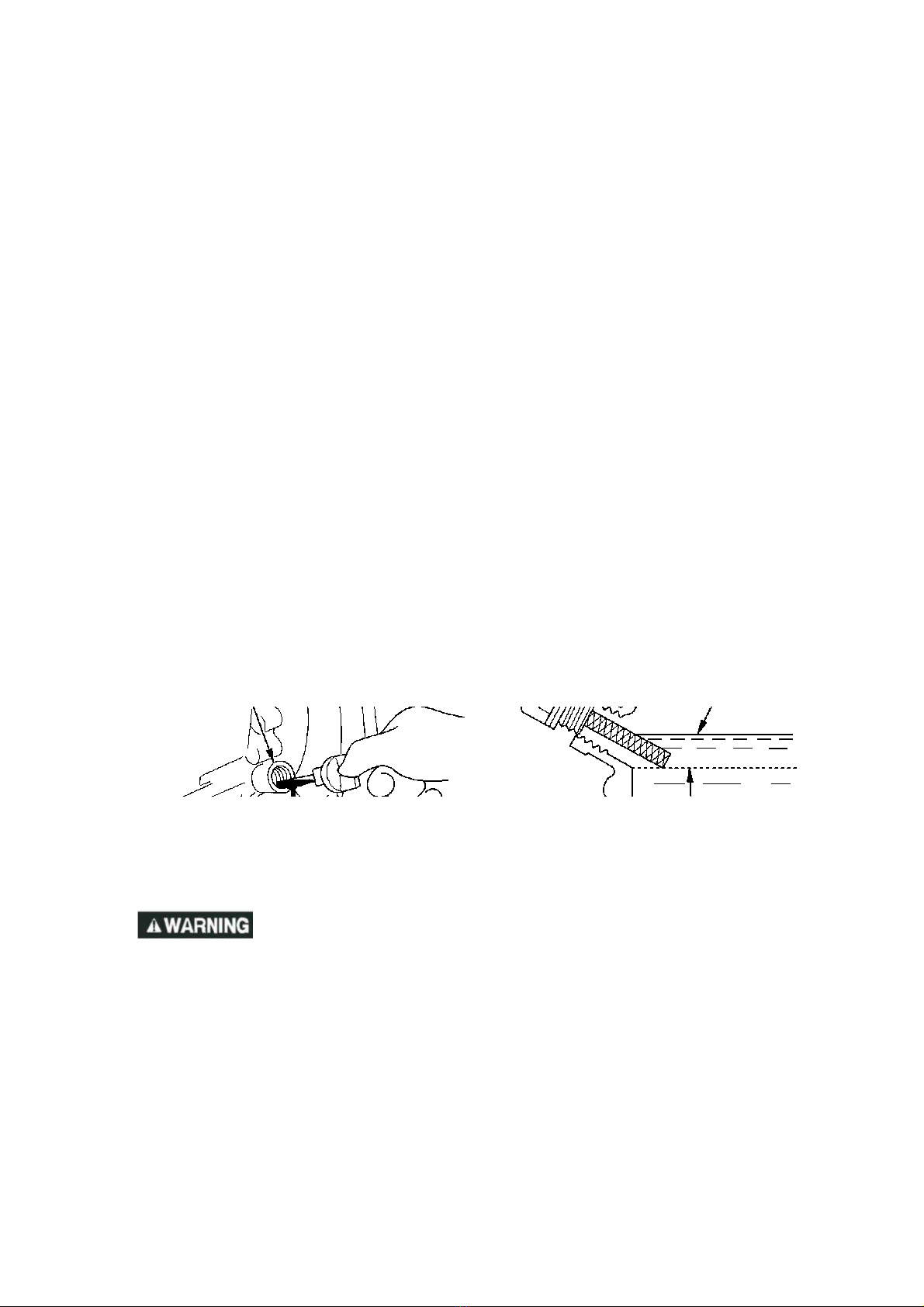
Refuel With Care
Gasoline is extremely flammable, and gasoline vapor can explode. Refuel
outdoors, in a well-ventilated area, with the engine stopped and the pump on a
level surface. Do not fill the fuel tank above the fuel strainer shoulder. Never
smoke near gasoline, and keep other flames and sparks away. Always store
gasoline in an approved container. Make sure that any spilled fuel has been
wiped up before starting the engine. After refueling, make sure the tank cap
closed properly and securely.
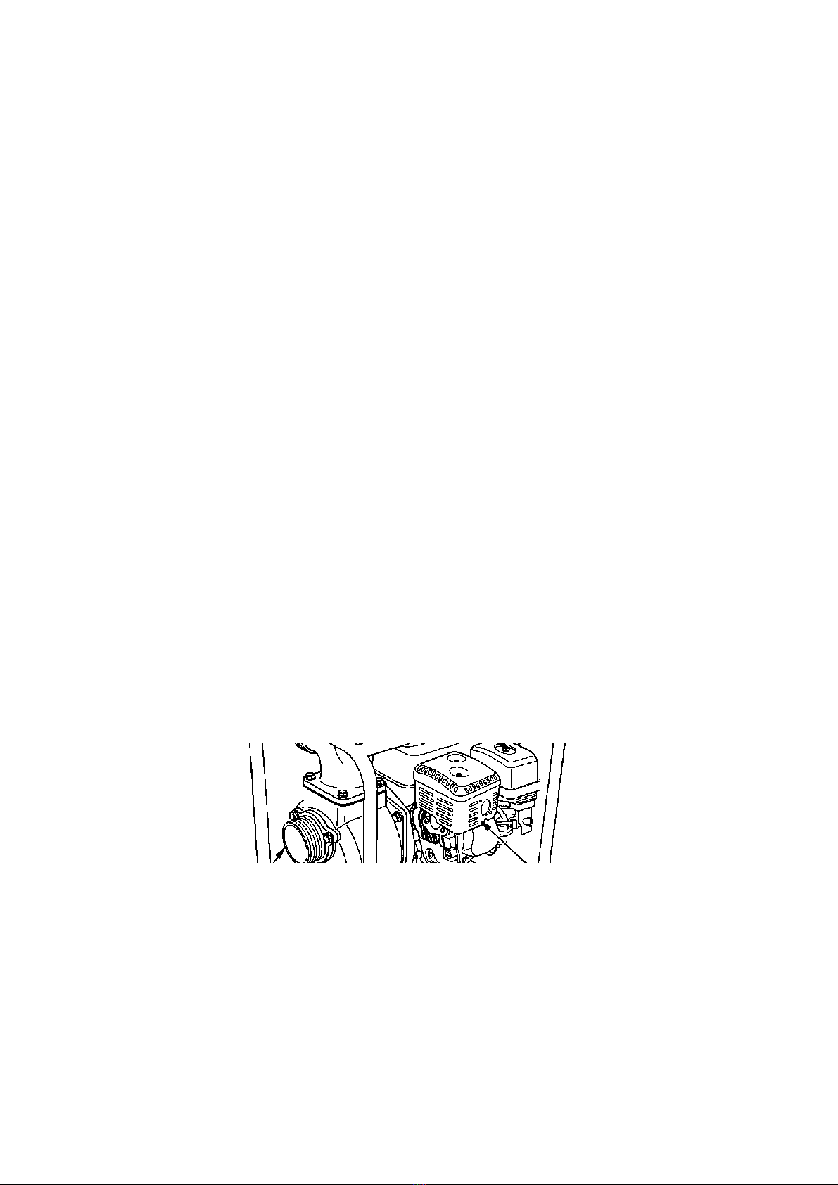
Hot Exhaust
The muffler becomes very hot during operation and remains hot for a while after
stopping the engine. Be careful not to touch the muffler while it is hot. Let the
engine cool before transporting the pump or storing it indoors.
To prevent fire hazards, keep the pump at least 3 feet (1 meter) away from
building walls and other equipment during operation. Do not place flammable
objects close to the engine.
Carbon Monoxide Hazard
Exhaust gas contains poisonous carbon monoxide. Avoid inhalation of exhaust
gas. Never run the engine in a closed garage or confined area.