IQsocket IQTS-GI500 User manual

User manual www.IQtronic.com
Intelligent power
sockets
IQsocket / IQTS-GI500
…makes your life more comforta le
U
ser Guide
IQTS-GI500
firmware documentation v.1.0.1
(for firmware v1.0.1)

2015 IQtronic technologies Europe s.r.o.
Page 2 of 28
1. Product features............................................................................... 3
2. Installation ...................................................................................... 4
2.1 Instalation rules for dual radio device ............................................. 5
3. Status page ..................................................................................... 5
3. Network configuration ....................................................................... 7
4. est rules – watchdog function. .....................................................10
5. GSM configurations .......................................................................12
5.1. Monitoring LAN network over SMS by GSM network. .........................13
6. Utility.............................................................................................13
7. Control socket.................................................................................16
8. Logging. .........................................................................................19
9. Quick setup. ...................................................................................20
10. XML data - status.xml ....................................................................21
11. Indicators .....................................................................................22
11.1. OK operations..........................................................................22
11.2. Error status. ............................................................................22
12. Output socket wiring diagram..........................................................23
13. IQLocator utility.............................................................................23
15. echnical specifications...................................................................27
16. Operation, maintenance and safety recommendations ........................27

Page 3 of 28
1. Product features
IQsocket IQ S-GI500 is a member of family of intelligent power sockets
brought to you by IQtronic technologies Europe, Ltd.
IQsocket IQ S-GI500 allows you to control of any electric appliance connected
to the device’s socket remotely over any IP network, including internet or by
GSM network. You can use for this purpose any device supporting internet
browser (H P protocol) such as PC, smartphone etc) or GSM.
It has implemented PING function for monitoring LAN network by GSM.
Výstupem zařízení je zásuvka 230V s maximální proudovou zátěží 16A.
Veškeré změny stavu výstupní zásuvky, příchozí SMS a hovory jsou ukládány
do logu.
In general, IQsocket IQ S-GI500 has following features:
•Controlling (turn on, turn off; restart by cutting power for short time)
of any electric appliance connected to the switched socket by H P and
by GSM SMS or manually by pressing pushbutton on IQ S-GI500 body
•Configuring IQ S-GI500 parameters by H P protocols, password
protected
•XML and H ML status page, can be excluded from password protection,
for easier integration with your web applications
•Can send SMS traps throught GSM network.
•IQLocator configuration utility allowing to autodiscovery your IQsocket
devices within LAN network, setup IP address and upgrade firmware
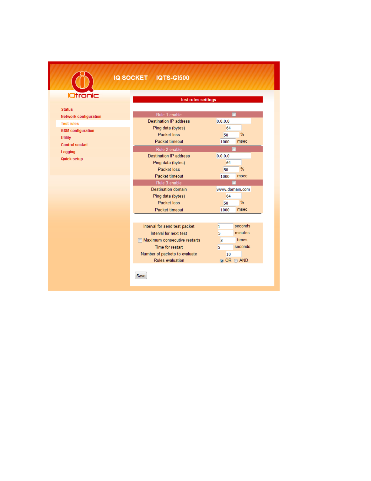
•Automatic control based on evaluation of ICMP packet loss with up to
three independent rules – watchdog function
•Automatic control based on day of week and time – scheduler function
•Real time clock synchronized using N P protocol
•On board temperature sensor to monitor internal temperature
•Support remote firmware upgrade
•Event log storing up to last 50 events, such as socket on/off changes,
device startups, LAN port connectivity, firmware upgrade etc.
•iny footprint firmware is efficiently coded in C/assembler, there is no
Linux or other operating system inside, so startup times are really
short (<3sec) and tcpip stack is clean with no hidden bugs ;-)

Page 4 of 28
2. Installation
Once you plug your IQsocket IQ S-GI500 into a live
electric socket, it become powered on and starts
operation.
You can verify it by observing status of the LEDs:
•Once AC power is connected, all three LED
indicators will blink shortly and internal self-
test is performed. hen, if everything is ok,
the Power LED (Red) will shine permanenelty. If SIM card is fully
operating then Power LED shine/blinks Blue.
•LINK/AC (Green) – solid light indicated established Ethernet link,
blanked for short time when an Ethernet activity occurs
•he Output LED (Yellow) indicates state of output socket. Sold light
means socket is active – appliance plugged into the output socket is
operating and vice versa.
Your IQ S-GI500 is now ready for use.
IQsocket IQ S-GI500 is equipped with an internal web server, which provides
an easy to use, intuitive and convenient way of management. You can both set
up configuration and operation parameters and get information about device’s
status.
In order to access the web interface, it is necessary to setup IP network
address on your PC properly.
Default IP address of the IQsocket IQ S-GI500 is 192.168.0.100, network
mask 255.255.255.0.
In order to access your IQ S-GI500, it is necessary to setup IP address of your
computer, connected to the same Ethernet network as the IQ S-GI500
properly – in this case set the IP address of the network adapter to
192.168.11, mask 255.255.255.0.
You can also change the IP address of your IQ S-GI500 using IQLocator utility,
Once you have properly set IP address of your PC, open the address of your
IQ S-GI500 (default 192.168.0.100) in your favorite internet browser:
If everything is ok, status page will be displayed.

Page 5 of 28
2.1 Instalation rules for dual radio device
You are obliged to follow the following rules during instalation of any radio
device working in duplex mode.
•Use an antenna with a higher gain and lower SVR in case of low signal
level.
•Do not instal your antenna near metal objects.
•Do not instal your device in the environment which can limit the signal
level, not in metal boxes!
•Your antenna cannot be directed towards the internal device electronics.
Otherwise, we cannot guarantee that your device will work properly.
In order to place your antenna properly, please use the grey area indicated at
the front panel of your device.
3. Status page
Provides summary of device status:
Explanation of parameters:

Page 6 of 28
Section System information provide basic status information, such as Device
name and Location, info on time, firmware version, Ethernet MAC address and
temperature reading of internal temperature sensor.
Section Last event provides date/time of last change of socket state and
current socket state.
Socket status – Turned ON , Turned OFF, Restarted.
GSM status – GSM is disabled,Preparing GSM,SIMcard is not inserted,
SIMcard is not ready, Searching ..., Logged in, Signal : 90 %.
Section Rules status informs about currently active automatic rules evaluating
ICMP packet loss to chosen hosts.

Page 7 of 28
3. Network configuration
Here you can configure networking and security parameters:
IP address
You can setup IP networking parameters such as IP address, Network mask
Default Gateway, DNS servers; please ensure to enter proper values. Please
note it is necessary to define a fixed IP address even if case you are using a
DHCP environment.
Note…
When your local network is usin private addresses behind
a NAT router and you would like to make your IQTS-GI500
accessible from the Internet, it is necessary to setup port
mappin (forwardin , server rule) in your router for the IP
address assi ned to IQTS-GI500 and selected ports, e. .
port TCP 80 for accessin web interface.
SOHO example: Your network contains a modem/router with NA for internet
access, having IP address 192.168.1.254. Simply find an unused IP address
from the private network range it use (192.168.1.1-192.168.1.253) e.g.

Page 8 of 28
192.168.1.200, double check it is not used e.g. by using Ping command from
your PC:
C:\>ping 192.168.1.200
Pinging 192.168.1.200 with 32 bytes of data:
Request timed out.
hen assign the 192.168.1.200 to the IQ S-GI500 by either IQLocator utility
or by web interface and use address of the router (192.168.1.254) in both
Gateway and DNS fields.
NTP setup
IQ S-GI500 can synchronize its clock from an NTP (Network ime Protocol)
server, please don’t forget also to define time zone. Please note N P feature
will work only if IQ S-GI500 will have access to the Internet.
Note…
It is hi hly recommended define NTP properly and allow
your IQTS-GI500 accessin the Internet; otherwise
lo in and scheduler feature can’t work properly.
Password protection
You can change/define a login username and password for protecting access to
web interface. It comes with no password by default.
Note…
If you want to disable password protection, enter blank
lo in password.
You can also activate exception from password protection for pages status.xml
and/or status/html – when exceptions are active, those pages will be then
always available without password, which is useful for further processing of the
status information e.g. by scripts.

Page 9 of 28
HTTP port
It is possible to change port for the web interface from default value 80 by
entering new value to HTTP port field.
SNMP
SNMP can be deactivated by unchecking the SNMP checkbox, it is active by
default. You can change passwords for SNMP read and write communities
(default value is “public”). When there is an output control event resulting from
assessment of automatic packet loss rules – the watchdog feature; IQ S-
GI500 can send SNMP trap messages to defined IP address besides operating
the relay of the socket, simply check particular check boxes Relay and/or Send
TRAP.
he SNMP time for restart defines how long is socket turned off when restart
command is issued via SNMP.
Add log events
You can select, which events to write into the event log: Power UP will write
event at every device startup and time has been successfully synchronized
from N P server; Ethernet LINK will write event at every time when Ethernet
link has been established.
Output socket state after startup
You can choice which state will have output socket after device will be powered
on: to be off, on, or to remember last state before device has been turned
off/power has been lost.

Page 10 of 28
4. Test rules – watchdog function.
Basically, you can define up to three test rules, two with numerical IP address
of evaluated host, third rule can be defined using host name, and it’s IP
address will be resolved via DNS. Each rule is sending periodically ICMP test
packets to the host and when number of received ICMP replies is lower than
allowed packet loss, rule will generate request for output control event, which
can lead to restart of the output socket, sending of SNMP trap or both,
depending on configuration. Finally, output control event is performed using
logical OR or logical AND operations over the results (output control event
requests) of particular rules.
Defining rules
Each rule can be enabled or disabled by checking the checkbox. Enter IP
address (Rule 1, Rule 2) or host name in case of the Rule 3, then size of ICMP
frames, maximum allowed packet loss in % and Packet timeout interval, time

Page 11 of 28
how long will device wait for answers from the host – ICMP answers coming
later that the Packet timeout will be considered as lost.
Note…
If you set Packet timeout to 0 (zero) value, device will use
the value of Interval for send test packet as the Packet
timeout interval.
Rules evaluation
You can define periodicity of sending test ICMP packets by entering it into
Interval for send test packet field with allowed range 2-20 seconds.
Interval for next test is time delay till testing will begin after device has been
started up or a rule has been activated (packet loss to a host detected).
You can limit maximum number of consecutive restart attempts by setting
Maximum consecutive restarts parameter to prevent continuous restarting e.g.
if there is a serious problem preventing target host to be recovered back by a
restart via power cycling.
Hold restart for - defines time interval (10-600s) for waiting to connection
recovery. If also this (interval, delay) expires, output socket will be restarted.
It is also possible to cancel (this)
action by SNMP packet
.
Restart socket hold time determines time interval how long is cut power of the
output socket during a restart attempt.
Number of packets to evaluate represents how many test packets is used for
evaluation of packet loss.
Rules evaluation allows to choose when an output control event (restart and/or
SNMP trap) will be performed – in case of selected OR, it will be performed
when ANY from rules is positive; while AND require that ALL rules must be
positive.

Page 12 of 28
5. GSM configurations
Allm texts has length up 30 characters.

Page 13 of 28
5.1. Monitoring LAN network over SMS y GSM network.
1. STEP - send SMS with text PING 192.168.0.111 to phone number to SIM
card inserted inside device.
You have several options: PING www.domain.cz OR PING ip address/64, PING
www.domain.cz/1024, the number behind '/' is data length in ICMP packet.
PING with IP address or domain name without parameters means PING with
data length 32 bytes.
2. STEP - device GI500 will send 10 test ICMP packets with interwall 1
second, if input is set correctly.
3. STEP - device GI500 will send PING result back to user.
6. Utility
his page gives you possibility to restore factory default configuration, reboot
device, upgrade firmware and clear statistics data:

Page 14 of 28
Restoring default configuration
Restore default confi uration will revert all settings to the factory default
values. It is necessary to reboot the device in order to activate new values
using Reboot button:
Clearing statistics
Clear statistic data will erase all collected statistics data displayed in Status
page.

Page 15 of 28
Firmware upgrade
Using Browse button select file containing new firmware and then click to
Upload. Up rade process will take about 50 seconds, which is indicated by fast
blinkin of the Power LED (red) and followin messa e will be displayed I case
of success:
In case of an error will be detected, following message will be displayed:
Note…
You can also up rade firmware usin IQLocator utility,
please see current chapter for more information.
WARNING!
Do not remove power durin a firmware up rade process, as it
can render your device inoperational!

Page 16 of 28
7. Control socket
Here you can control the output socket manually and schedule automatic
actions based on date/time.
Socket status
op of the page contains status row displaying current status of the socket:

Page 17 of 28
Manual control
Simply click to the buttons to turn on, turn off and restart (change current
state to opposite one temporary for given number of seconds).
Scheduler
his feature allows you to schedule output socket status, up to 50 records are
supported.
Scheduler function use date/time synchronized by N P protocol, so your IQ S-
GI500 must have access to the Internet (or to an N P server located within
your private network), see also chapter Chy a! Nenalezen zdroj odkazů..
Each scheduler record defines target socket state at given time. It is allowed to
manually control the socket while scheduler is active – each change is done
only at particular time.
Each scheduler record is having following structure:
DOW,…DOW,HH:MM, action
Where:
oDOW means Day of week, coded as first two letters of English day
names: Mo, u, We, h, Fr, Sa, Su;
oHH:MM means time in form of hour:minute in 24h format;
oAction means target socket state – off, on.
Example
Enter following rows:
Mo, u,We, h,Fr,Sa,Su,20:00,Off by clicking to Save button
Mo, u,We, h,Fr,Sa,Su,21:00,On by clicking to Save button
Mo, u,We, h,Fr,Sa,Su,22:00,Res by clicking to Save button
and then activate scheduler by clicking to checkbox Enable scheduler

Page 18 of 28
So scheduler will every day at 20:00 turn the output socket off, turn it on
daily at 21:00 and restart it on daily at 22:00 for option: ime for restart
output (Network settings).
You can use any combination of days of week, such as:
Sa,Su, 20:00, Off
Sa,Su, 21:00, On
to control the socket during weekends.
I you want to delete particular scheduler row, simply enter copy of the row and
click to Delete button; you can also enter a part of row and all similar rows will
be deleted.
If you want to delete all scheduler records, enter text ALL and click to Delete
button.

Page 19 of 28
8. Logging.
his page display events recorded in the event log:
Event log can contain up to 100 records, oldest records being rewritten when
log is full.
Automatically are recorded socket change events and firmware upgrade,
optionally Ethernet link status and device startups, which can be configured in
Network configuration menu.
All events are time stamped when time has been successfully obtained from an
N P server, so your IQ S-GI500 must have access to the Internet (or to an
N P server located within your private network), see also chapter Chy a!
Nenalezen zdroj odkazů..
Events can be sorted by time (last event is shown like last line).
Explanation of event types
Upgraded new firmware an upgrade firmware has been done
POWER UP 0 device has been turned on by applying
power
POWER UP 1 device has been manually rebooted
Restart www.domain.com 100% restart due to www.domain.com has been
inaccessible, with ICMP packet loss 100%

Page 20 of 28
DEVICE OVERHEA Overheat condition, allowed internal
temperature is 50°C.
URN ON by BU ON socket has been turned on by the push
button
URN OFF by BU ON socket has been turned off by the push
button
URN ON by SCHED socket has been turned on by scheduler
URN OFF by SCHED socket has been turned off by scheduler
And more...
9. Quick setup.
his page provides setting up of basic networking and ICMP packet loss test
rule parameters of IQ S-GI500 in an easy way suitable to less experienced
users.
In case of settings entered are wrong or missing, user is informed about it the
status row; settins then must be repeated until they are accepted, which is
indicated by following messgae in the status row:
New settings is then passed into est rules and are activated.
Possible errors include:
Table of contents
Other IQsocket Accessories manuals