/22
IRMA MATRIX R2 Option Door Contact | Mounting Manual
released
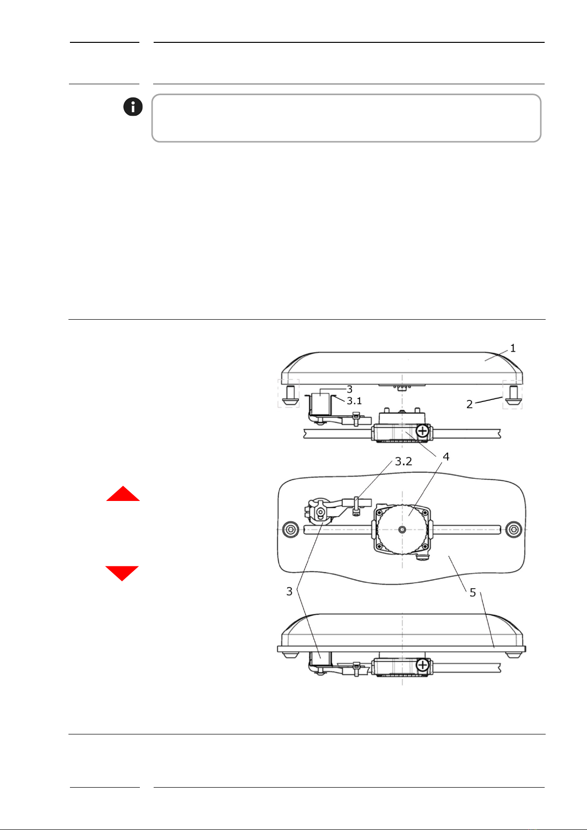
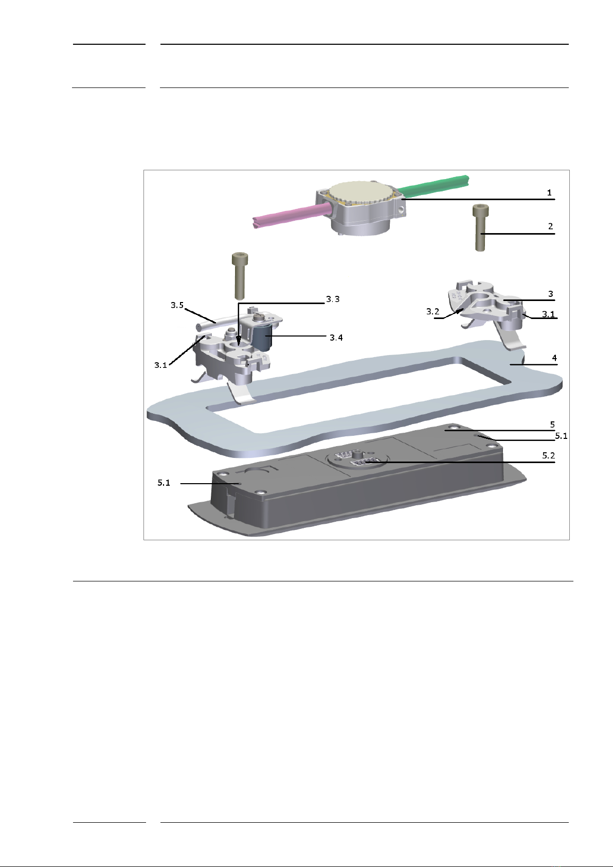
2.2 Flush mount version with door contact magnet
Mounting with sCON-Standard (S)
sCON connector for sensors
Cylinder head screws (2 screws)
2 spring holders with pre-mounted
leaf spring
3.1 Eye for attaching the zip tie
3.2 2 guide grooves for sliding the
holding system under the screw
head
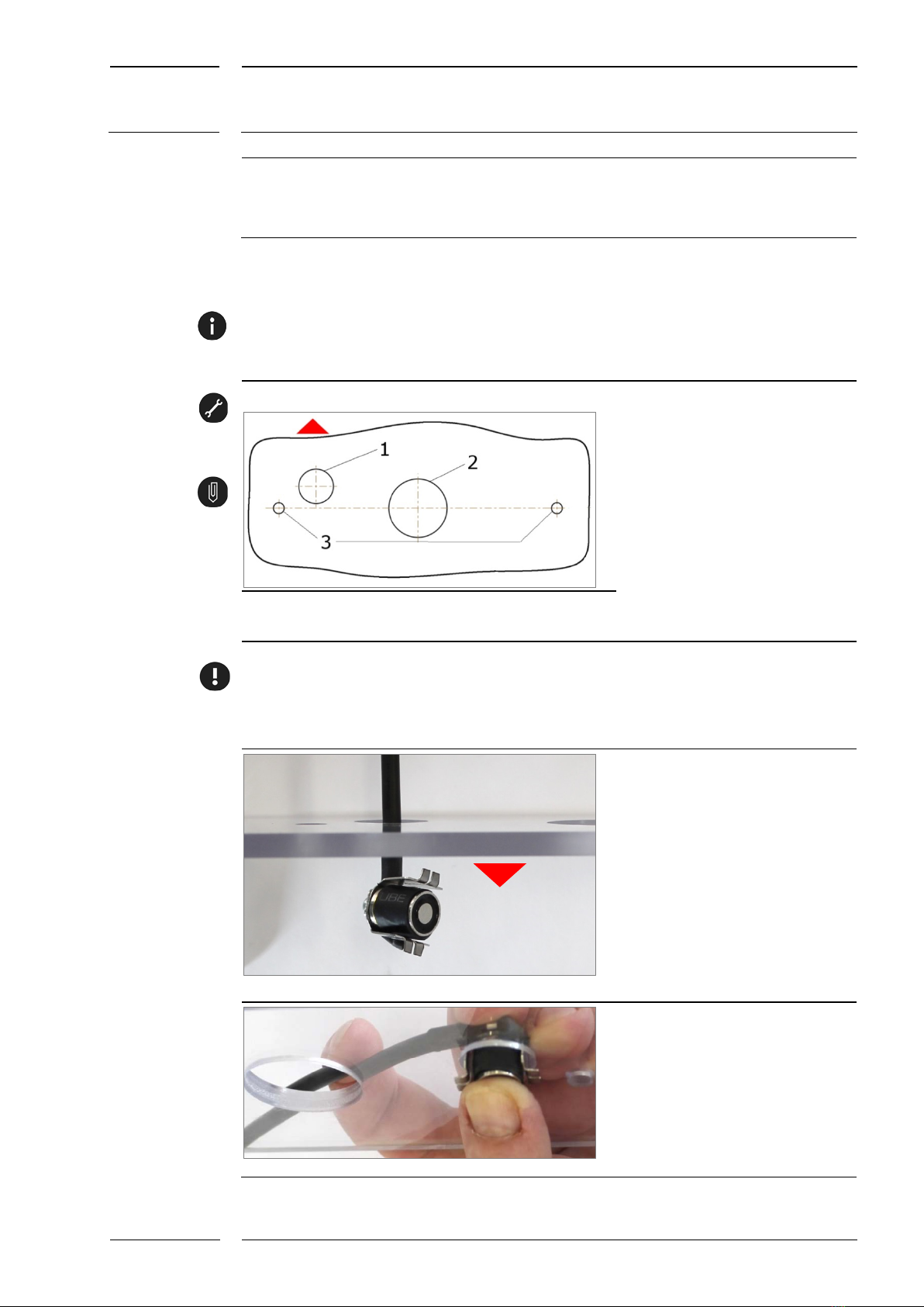
2 holes for the cylinder head screws for
centring and arresting the sensor
1 door contact magnet (also referred to as
magnet, electromagnet) with support,
pre-mounted to the spring holder
Connection cable of door contact magnet
Cove (here e.g. 4 mm thick)
with rectangular cutout
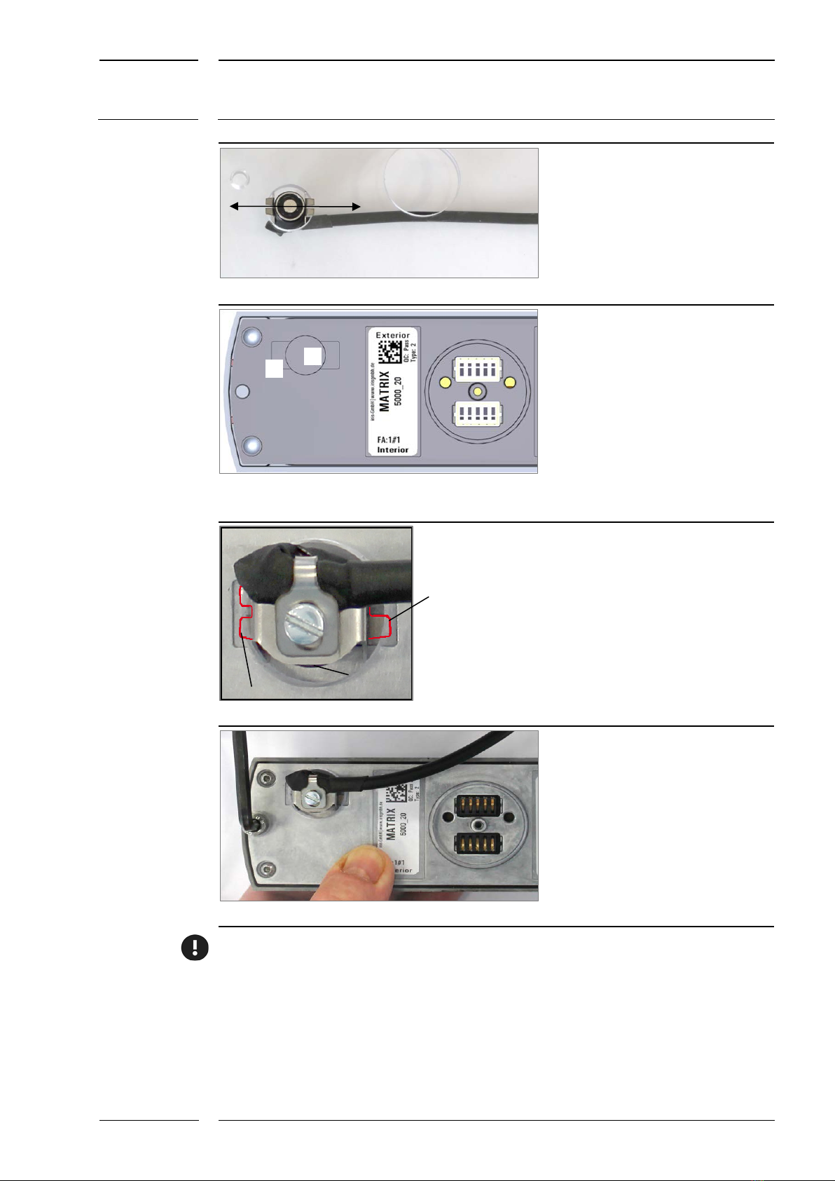
MA MATRIX sensor, flush mount
version
Threaded hole for the cylinder head
screw for mounting
sCON connection on the sensor
2: Flush mount version: mounting of door contact magnet with sCON-S