IPU 40420 Issue 1 Page 2 of 26
Contents Page
1.
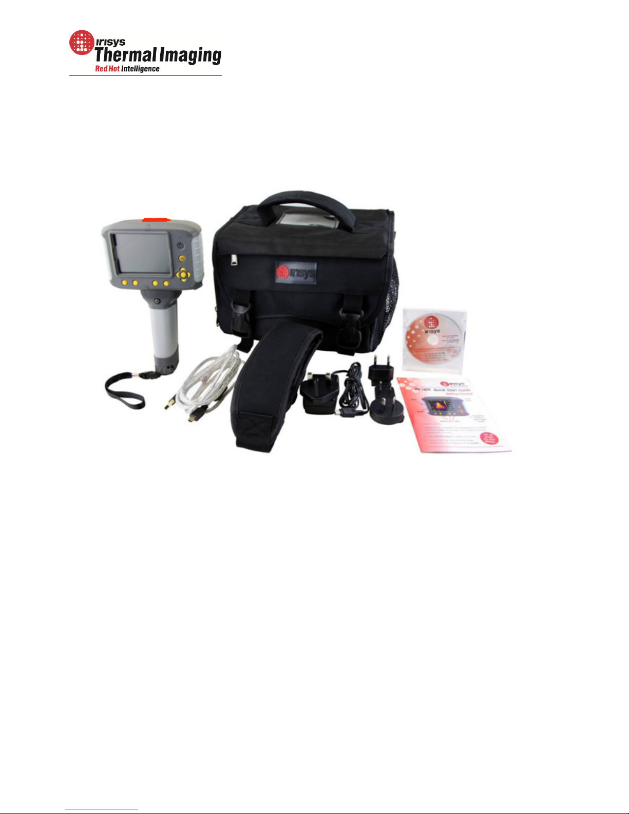
CONTENTS. ........................................................................................................ 3
2.
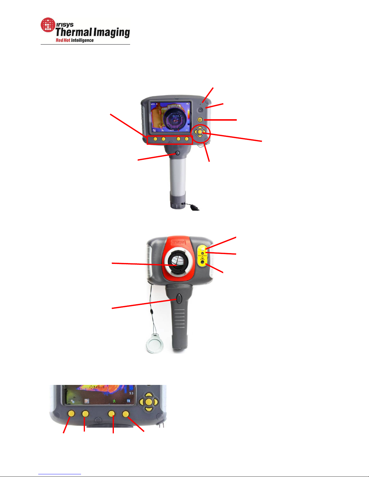
MAIN CONTROLS. .............................................................................................. 4
2.1.
B
ACK
................................................................................................................... 4
2.2.
F
RONT
................................................................................................................. 4
2.3.
H
OTKEY BUTTONS
.................................................................................................... 4
3.
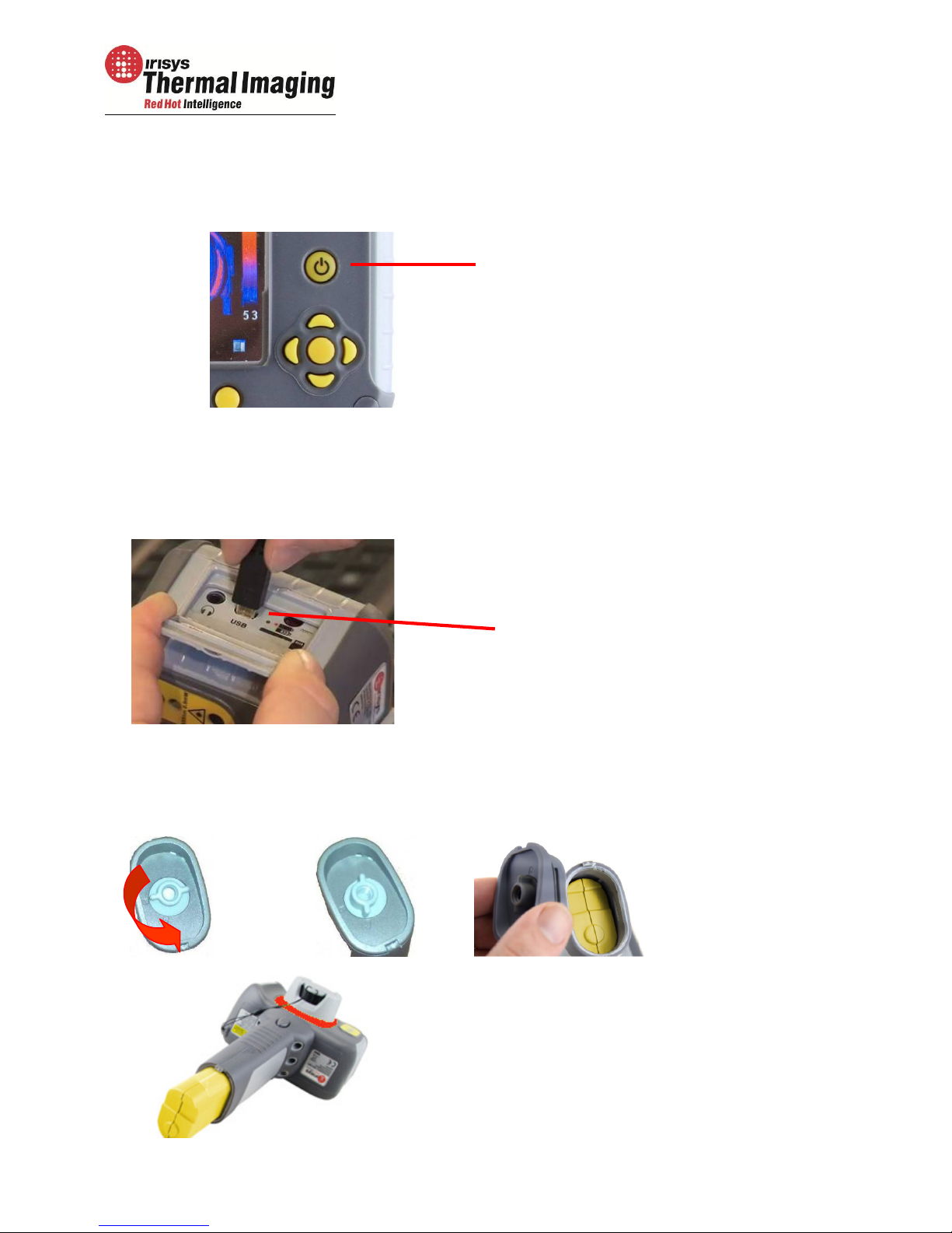
GETTING STARTED. ............................................................................................ 5
3.1.
S
WITCHING THE CAMERA ON
/
OFF
.............................................................................. 5
3.2.
C
HARGING THE BATTERY
........................................................................................ 5
3.3.
C
HANGING THE BATTERY
........................................................................................ 5
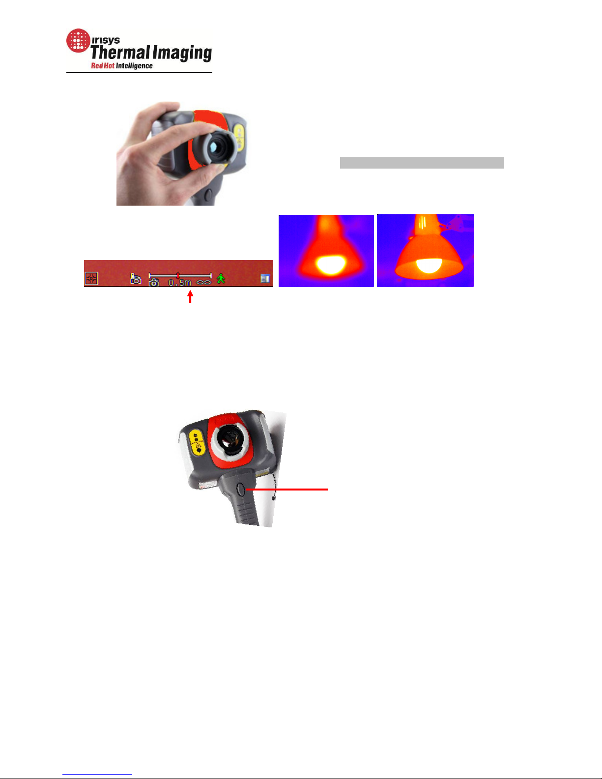
3.4.
F
OCUSSING
....................................................................................................... 6
3.5.
S
AVING AN IMAGE
............................................................................................... 6
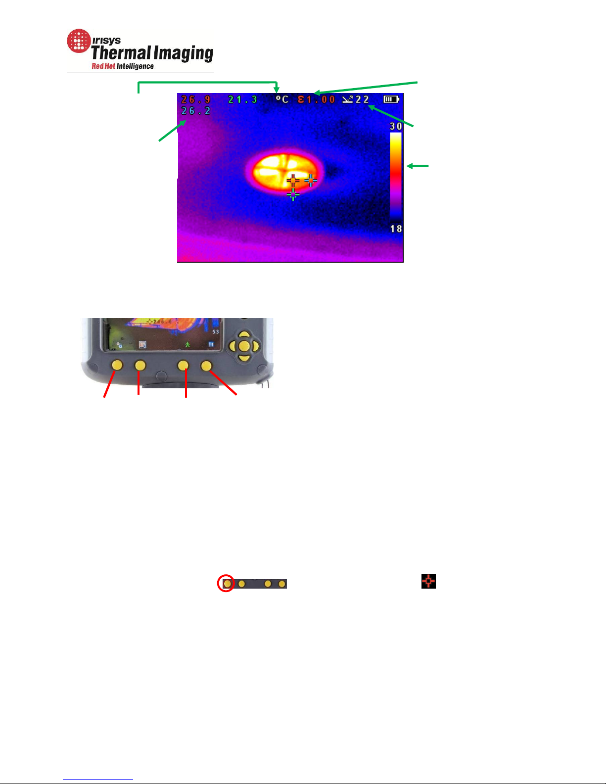
3.6.
T
EMPERATURE MEASUREMENT
.................................................................................. 6
4.
HOTKEY BUTTONS. ............................................................................................ 7
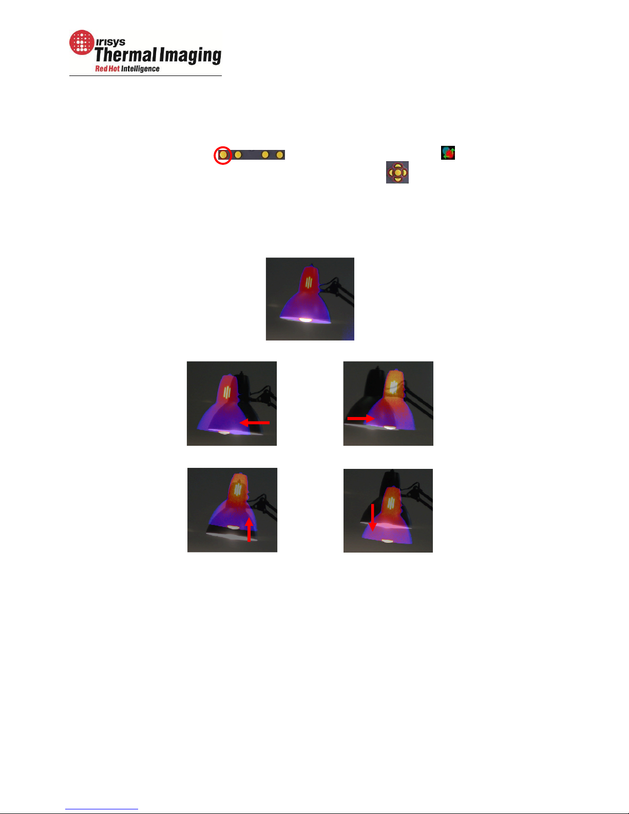
4.1
M
OVING THE CURSOR
........................................................................................... 7
4.2.
I
MAGE ALIGNMENT
............................................................................................... 8
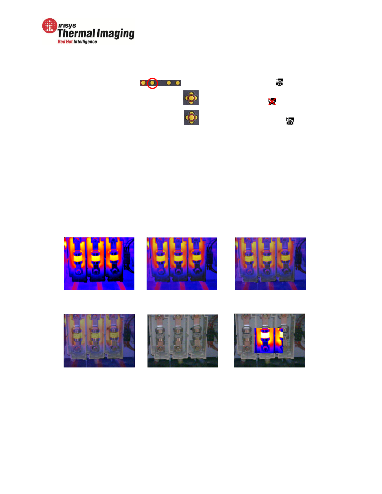
4.3.
T
URNING THE VISIBLE IMAGE OFF AND ON
.................................................................... 9
4.4.
T
HERMAL AND VISIBLE IMAGE BLENDING
...................................................................... 9
4.5.
M
ANUAL CONTROL
..............................................................................................12
4.6.
L
IGHT
.............................................................................................................12
4.7.
I
MAGE FREEZE
...................................................................................................12
4.8.
M
ENU
.............................................................................................................12
5.
MENU STRUCTURE. .......................................................................................... 13
5.1.
I
NFRARED SETTINGS
..........................................................................................14
5.2.
M
EASUREMENT OPTIONS
.....................................................................................15
5.3.
C
AMERA SETTINGS
...........................................................................................17
5.4.
A
UDIO SETTINGS
.............................................................................................18
5.5.
I
MAGE
B
ROWSER
..............................................................................................19
5.6.
D
ATE
&
T
IME SETTINGS
......................................................................................19
5.7.
L
ANGUAGE
S
ELECTION
.......................................................................................20
5.8.
D
ISPLAY
S
ETTINGS
...........................................................................................20
6. ADDING CAPTIONS WHEN SAVING IMAGES. ........................................................ 21
6.1.
V
OICE MESSAGE
.....................................................................................................21
6.2.
T
EXT CAPTIONS
......................................................................................................22
APPENDIX ................................................................................................................ 23
A1.
E
MISSIVITY TABLES
..................................................................................................23
A2.
F
ULL ICON LIST
.......................................................................................................24
A3.
T
ECHNICAL SPECIFICATION
.........................................................................................25