IPU 40108
Page 2 of 29
Contents:
1
INTRODUCTION.................................................................................................................................... 3
2
GETTING STARTED.............................................................................................................................. 3
2.1
UNPACKING......................................................................................................................................... 3
2.2
POWERING THE IRI 4010..................................................................................................................... 4
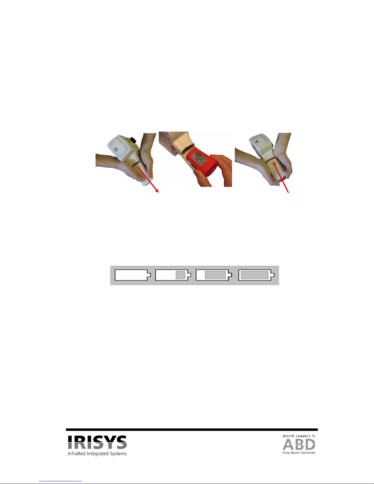
2.2.1
Using Battery Power – Inserting the Battery.............................................................................. 4
2.2.2
Using AC Mains Power.............................................................................................................. 4
2.2.3
Battery Charging......................................................................................................................... 5
3
OPERATING THE IRI 4010 THERMAL IMAGER ........................................................................... 5
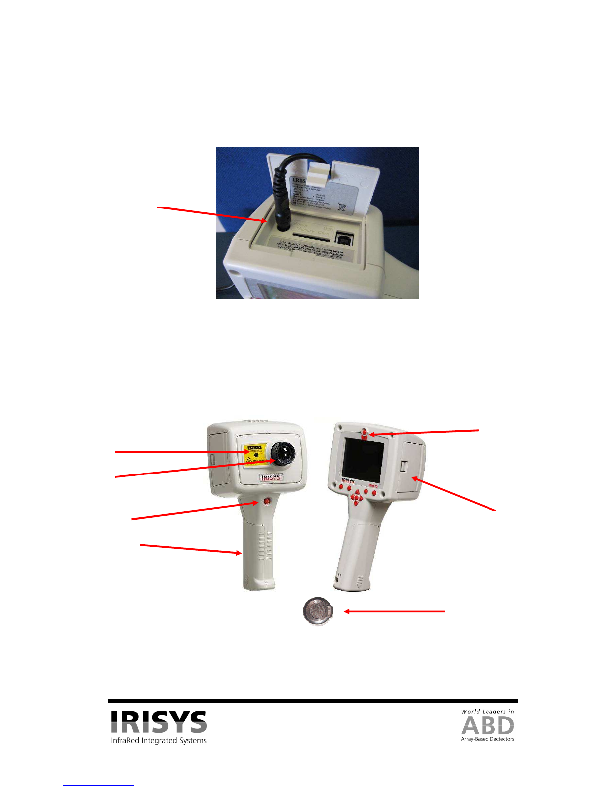
3.1
HARDWARE......................................................................................................................................... 5
3.2
SWITCHING ON THE IRI 4010............................................................................................................... 6
3.3
INFORMATION SPLASH SCREEN........................................................................................................... 6
3.4
USING THE IRI 4010 THERMAL IMAGER.............................................................................................. 7
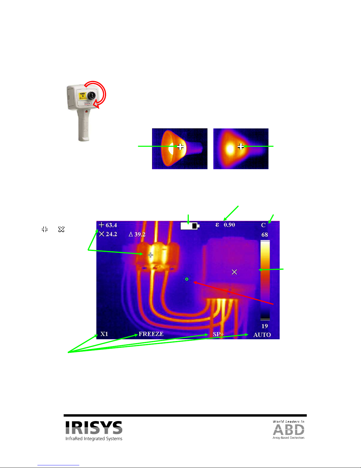
3.4.1
Focusing ..................................................................................................................................... 7
3.4.2
Screen Display Items.................................................................................................................. 7
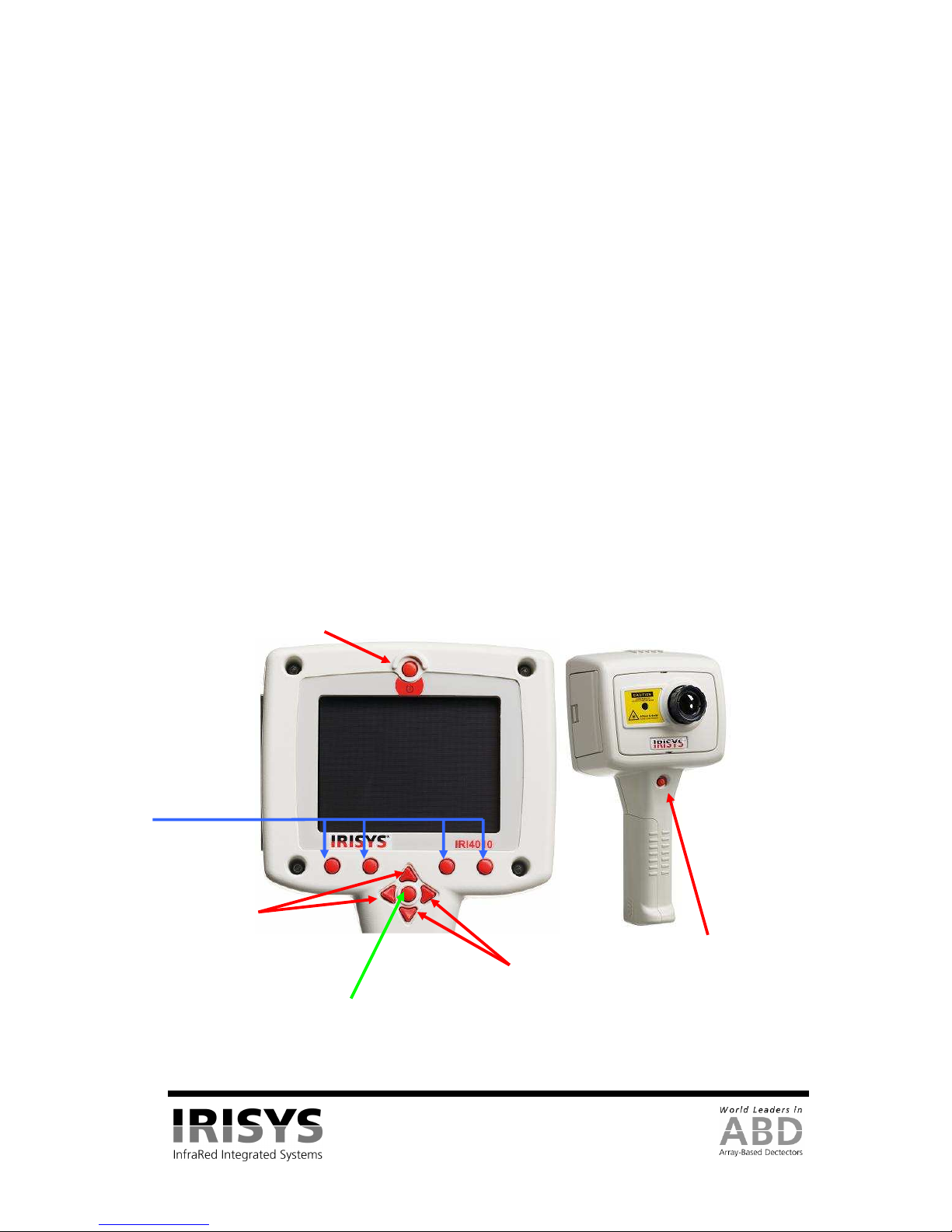
3.4.3
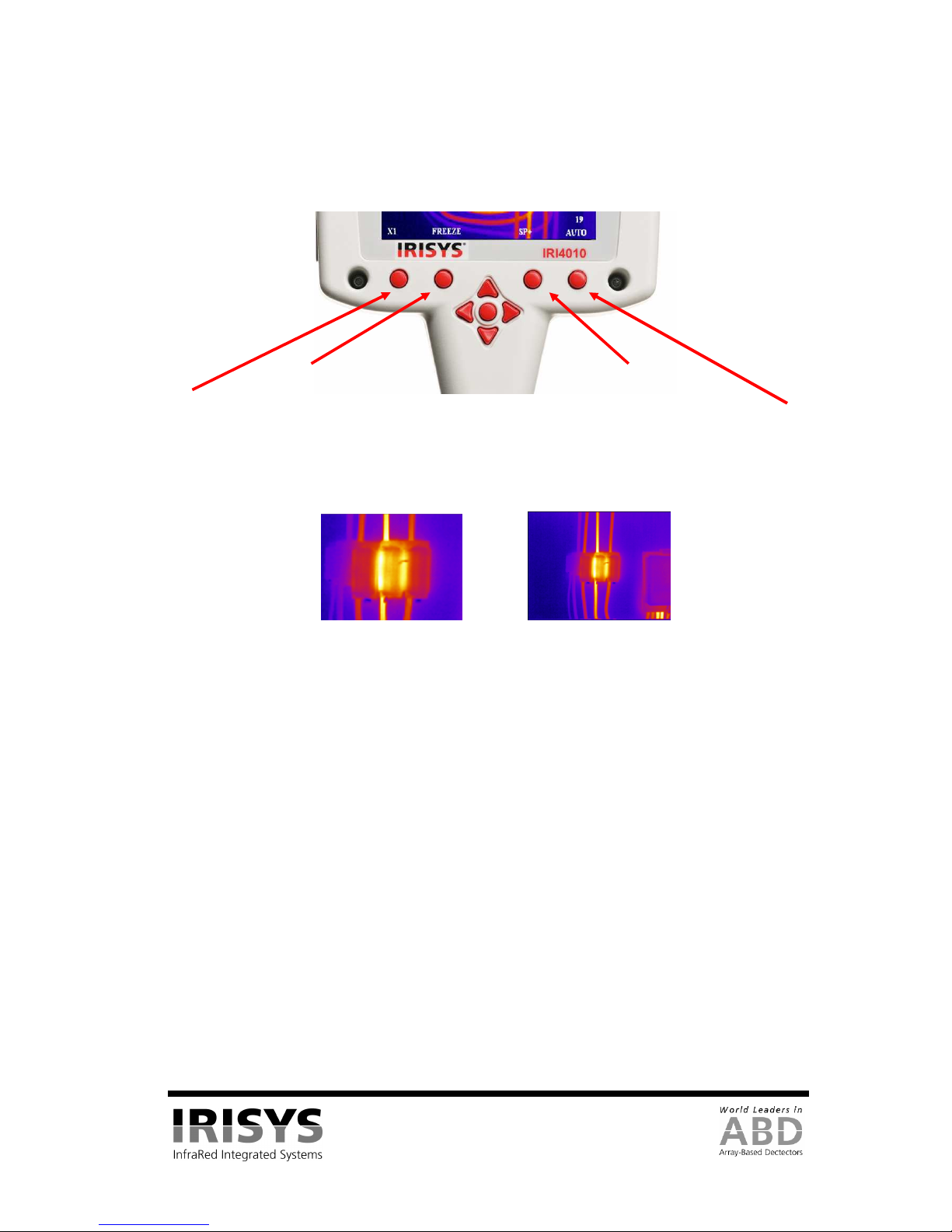
Buttons........................................................................................................................................ 8
3.4.4
IRI 4010 Hot Button Operation.................................................................................................. 9
3.4.4.1
Hot Button 1 – Zoom..............................................................................................................................9
3.4.4.2
Hot Button 2 – Freeze/Save....................................................................................................................9
3.4.4.3
Hot Button 3 - Direction Buttons Control...............................................................................................9
3.4.4.4
Hot Button 4 – Auto / Manual ................................................................................................................9
3.4.5
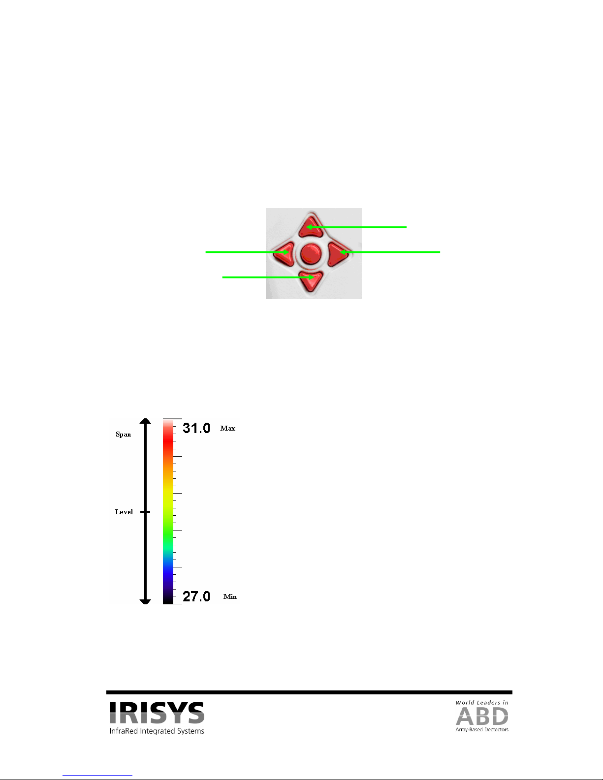
Directional Buttons................................................................................................................... 10
3.4.6
Image Adjustment..................................................................................................................... 10
3.4.6.1
Level and Span Definitions...................................................................................................................10
3.4.7
Menu Operation and Functions................................................................................................. 11
3.4.7.1
Measurement Settings...........................................................................................................................11
3.4.7.2
Camera Settings....................................................................................................................................12
3.4.7.3
Image Browser Menu............................................................................................................................12
3.4.7.4
Clock/Calendar Settings........................................................................................................................12
3.4.8
Using the Laser Pointer ............................................................................................................ 13
3.4.9
Advanced User Functions......................................................................................................... 13
3.4.9.1
Brightness & Contrast Definitions........................................................................................................13
3.5
TECHNICAL ....................................................................................................................................... 15
3.5.1
Field Of View........................................................................................................................... 15
4
THERMAL IMAGE TRANSFER FROM IRI 4010 TO A PC.......................................................... 16
4.1
SD CARD........................................................................................................................................... 16
4.2
USB CABLE....................................................................................................................................... 16
5
USING THE IRI 4010 THERMAL IMAGER WITH A PC .............................................................. 17
5.1
PC REQUIREMENTS ........................................................................................................................... 17
5.2
INSTALLATION OF SOFTWARE ONTO PC............................................................................................ 17
5.3
OPERATING “IRISYS 4000 SERIES IMAGER”PC SOFTWARE ............................................................ 17
5.3.1
Menus and Toolbar................................................................................................................... 18
5.3.1.1
Menus ...................................................................................................................................................18
5.3.1.2
Toolbar..................................................................................................................................................27
6
EMISSIVITY LOOKUP TABLE ......................................................................................................... 28
7
CUSTOMER FEEDBACK.................................................................................................................... 29