Iritech IRISHIELD-UART MO 2120 User manual

August 2021
Document Version 0.7
IRISHIELDTM-UART MO 2120
HARDWARE DEVELOPER’S
MANUAL

Document
Change Record
This page records any updates and revisions made to the IriShieldTM-UART MO 2120
Hardware Developer’s Manual.
Doc ver.
Date
Change Description
0.2
05th Sep 2013
Draft version
0.3
10th Sep 2013
Format correction
0.4
26th Nov 2013
Adding parts description
0.5
07th Jan 2014
Update power management
0.6
13th Aug 2014
Update Memory Warranty
0.7
03rd Dec 2014
Update FPCB Connector
Note
The information contained herein is provided solely for the purpose of assisting customers
to understand how to operate and integrate IriTech’s hardware and software and is not to
be released, reproduced, or used for any other purpose without written permission of
IriTech, Inc.
IriTech reserves the right to make changes on this hardware and software with the intent
to improve its functionalities. Information and specifications contained in this document
are subject to change without prior notice and do not represent a commitment on part of
IriTech.
Copyright © 2021 IriTech, Inc. All rights reserved.

1.Preface.............................................................................................................................................................................................1
1.1 Purpose of this Document .........................................................................................................................................1
1.2 Intended Reader .............................................................................................................................................................1
1.3 Other Documentation .................................................................................................................................................1
1.4 Contact Information ....................................................................................................................................................1
2. Introduction ................................................................................................................................................................................1
3. Key Features..............................................................................................................................................................................2
4. Warnings and Precautions..............................................................................................................................................3
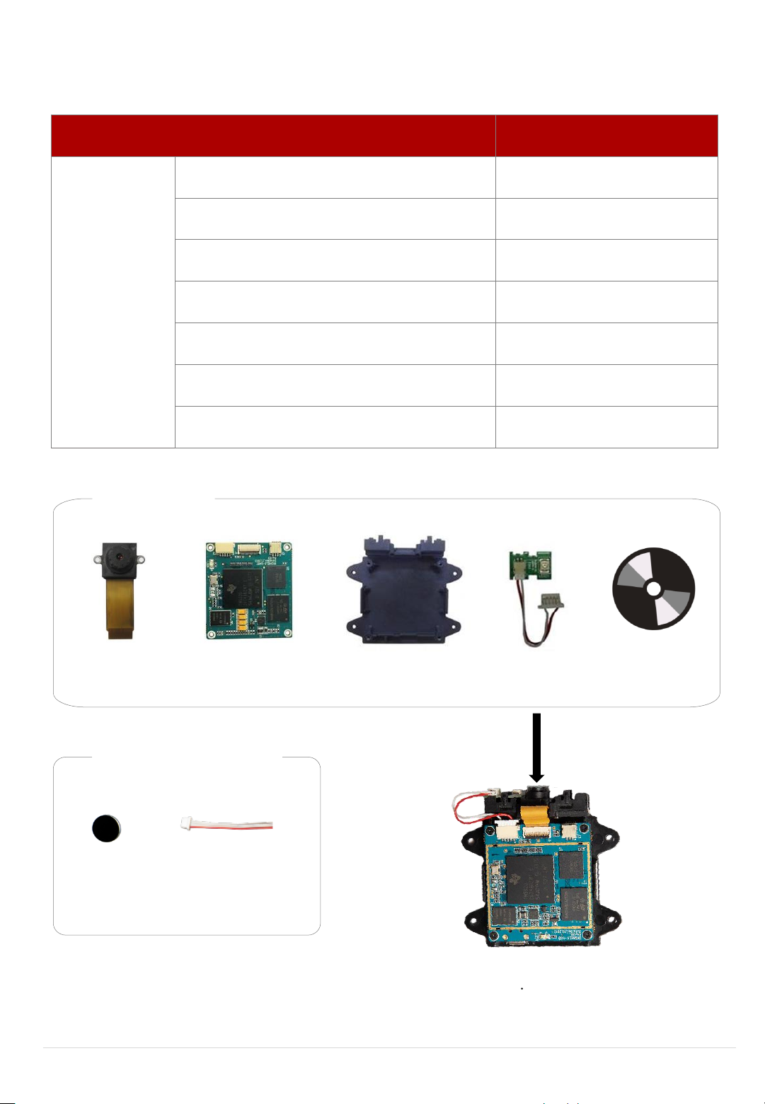
5. Product Inventory ................................................................................................................................................................. 4
6. Hardware Specifications.................................................................................................................................................. 5
7. IrishieldTM-UART MO 2120 BOARD...................................................................................................................................7
7.1 Mechanical Drawing ...................................................................................................................................................7
7.2 Functional Block Diagram.......................................................................................................................................7
7.3 Connector and Ass’y Cable Interfaces ......................................................................................................... 8
7.4 Deepsleep Mode.........................................................................................................................................................13
8. Camera Module....................................................................................................................................................................15
8.1 Camera Interface .......................................................................................................................................................15
8.2 Camera Mechanical Drawing ...........................................................................................................................15
9. IR-LED Ass’y Cable...............................................................................................................................................................16
9.1 Interface and Mechanical Drawing ................................................................................................................16
9.2 IR-LED Interface..........................................................................................................................................................16
9.3 IR-LED Mechanical Drawing............................................................................................................................... 17
9.4 5 Pin Housing Interface and Mechanical Drawing ............................................................................. 17
10. IriShieldTM-UART MO 2120 Module Frame .............................................................................................................18
10.1 Interface and Mechanical Drawing..............................................................................................................18
11. IR Filter.........................................................................................................................................................................................19
12. Capture Volume.................................................................................................................................................................. 21
13. Mount Cautions and Mount Guide.........................................................................................................................22
13.1 Mount Cautions........................................................................................................................................................22
13.2 Mount Guides.............................................................................................................................................................22
14. Legal Notice ..........................................................................................................................................................................24
14.1 Warranty Terms........................................................................................................................................................24
Table of
Contents

Hardware Developer’s Manual 1 © 2021 Iritech, Inc. All rights reserved.
1. Preface
1.1 Purpose of this Document
This Hardware Developer’s Manual provides detailed information useful for integrating the
IriShieldTM- UART MO 2120 into customer solutions, including hardware specifications,
component technology and component assembly.
1.2 Intended Reader
This document is written for hardware engineers and systems architects responsible for
designing and building complete biometrics solutions. Readers of this manual are assumed to
be familiar with basic engineering, electronics and biometrics concepts. There is no presumed
knowledge about any aspect of the IriShieldTM-UART MO 2120.
1.3 Other Documentation
For additional information about this product, refer to the following documents:
•IriShieldTM-USB and IriShieldTM-UART SW Developer's Manual –useful tips for IriShieldTMUSB
and IriShieldTM-UART SDK
•IDDK 2000 API Reference Manual for C_C++ –a detailed listing of the Application
Programming Interface (API)
1.4 Contact Information
If you have any questions or experience any problems using this hardware, please contact:
Phone: +1.703.877.2135 (USA)
+82.2.872.3812 (South Korea)
Email: collaboration@iritech.com
Your feedback is important for us to help and provide you with the most accurate and highest
quality information. If you have any comments about this documentation, please email us.
Include the version of this document and the section that pertains to your comments.
2. Introduction
IriShieldTM-UART MO 2120 is a revolutionary, monocular design that delivers the highest quality
autocapturing iris acquisition with an ease of use never achieved by older camera systems. The
system offers contactless, fast, standards-compliant iris acquisition in a small form factor that
is easy to house in a variety of packages. IriShieldTM-UART includes an embedded CPU that
enables on-board computing for automated quality-based iris image capturing, verification,
and identification without taxing the computing power of the host PC. IriShieldTM-UART provides
a PKI-based security infrastructure which creates a self-generated RSA-2048bit key and
generates a random one-time AES-256bit key for each session. As a result, this camera can
operate with nearly any host PC or mobile computing device. With its UART interface, compact
design, and sophisticated, easy-to-integrate accompanying software, IriShieldTM-UART
represents unprecedented value for iris biometrics identification.

Hardware Developer’s Manual 2 © 2021 Iritech, Inc. All rights reserved.
3. Key Features
•All-in-one Iris Identification camera in an ultra-compact size
•Top quality, fast, auto-capture and cost-effective iris recognition camera
•Automatic, easy-to-use, and light-weight
•Built-in Real-time Quality Evaluator and Automated Iris Acquisition
•Proven leading algorithms for template generation and comparison
•Powerful SDK for easy software development
•Safest for eyes: Safe infrared illumination at less than 2% of the LED Eye Safety
Standard Regulation
•Ready to be integrated with IriTech’s enterprise software environment
•Easy hardware integration

Hardware Developer’s Manual 3 © 2021 Iritech, Inc. All rights reserved.
4. Warnings and Precautions
IriShieldTM-UART includes sensitive electronics and optics. It is possible for IriShieldTM-UART
device to get these electronics damaged if you do not follow proper precautions:
•Clean regularly to remove dust, but do not use any cleaning solutions. Only wipe the
device with a smooth cloth or towel. Keep the lens free of dust and dirt, and use a
special cloth for optics in order to avoid scratching the optics.
•Do not allow water to leak into the device or operate the device in humid conditions
where water might condense upon the electronics.
•Do not operate device in places where temperate reach extremes beyond the stated
range.
•Do not place the device next to heating equipment.
•Do not place magnets near the device.
•Do not apply voltage or current beyond the stated range.
•Do not use the device for any purposes beyond those specified.
•Do not disassemble components from the boards or alter wiring or board design.
•Do not drop the device or submit to sudden impact or mechanical stresses.
•Handle the electronics with proper anti-static protection and techniques to prevent
shorting any microchips.
Any damage to the device caused by these activities will void the warranty.

Hardware Developer’s Manual 4 © 2021 Iritech, Inc. All rights reserved.
5. Product Inventory
Item
Quantity
Standard
IriShield™-UART MO 2120 Board
1
Camera Module
1
IriShieldTM-UART MO 2120 Module Frame
1
IR-LED Ass’y Cable
1
90mm Ass’y Cable (UART)
1
9ΦIR-Filter
1
Software Package
1
Camera Module
Software Package
IR-Filter
STANDARD
IriShield-UART MO 2120
Module Frame
Ass’y Cable (UART)
STANDARD
* Software Package can be downloaded from IriTech’s Website.
IR-LED Ass’y Cable

Hardware Developer’s Manual 5 © 2021 Iritech, Inc. All rights reserved.
6. Hardware Specifications
•Parts description and Mechanical Size
oIriShieldTM-UART MO 2120 Board: Main board (details from page 7)
36 x 40 x 6.9 mm (1.4 x 1.6 x 0.3 in)
oCamera Module: Specialized iris camera module (details in page 14)
30 x 15.4 x 7.1 mm (1.2 x 0.6 x 0.3 in)
oIriShieldTM-UART MO 2120 Module Frame: Frame for assembly
54.2 x 55 x 12 mm (2.1 x 2.2 x 0.5 in)
oIR-LED Board: IR LED board for infrared emission light (details from page 15)
10 x 12.5 x 3 mm (0.4 x 0.5 x 0.1 in)
o90mm Ass’y Cable: Communication cable with host (details in page 8, 11)
93 x 14 x 2.8 mm (3.67 x 0.55 x 0.1 in)
o9 ΦIR-Filter: High pass filter to remove visible light reflection in iris image
9 x 9 x 0.7 mm (0.36 x 0.36 x 0.28 in)
※Should be assembled in front of camera module (details from page 17)
•Power Requirements
Required Voltage
Vin
Min
Max
Recommend
External Power (DC +5V ± 5%)
Absolute
3.4V
6V
•Infinite loops are one of the most common problem that plagues developers. They
can occur in any programming language, in any application and in any coding style.
If infinite loop occurs, it can be solved by turning off/on the power switch. We
strongly recommend installing a switching circuit or power control switch to fix the
problem.
•Power Management
Mode
Current
Description
Active
MAX 220mA
Fully operating
Standby
MAX 70mA
Standby Mode
Sleep
MAX 40mA
Sleep Mode
Deepsleep
MAX 25mA
Deep Sleep Mode

Hardware Developer’s Manual 6 © 2021 Iritech, Inc. All rights reserved.
•Environmental
o-20°C to +60°C Storage
o0°C to +50°C Operating
•Camera Description
Image Resolution:
Output is ISO Standard of 640 x 480 pixels
(Optional: Higher Resolution output is available)
Sensor Resolution:
VGA
Pixel Density:
Normally greater than 210 pixels across iris diameter
Focal Distance:
4.7 cm ~ 5.3 cm (1.8 ~ 2.1 in) from the front of the top of
camera module (Focal Depth: 0.6 cm).
Optimal Distance:
5 cm (2 in) from the front of the top of camera
module
Field of View (FOV):
About 3.3 x 2.4 cm at 5 cm (1.3 x 0.9 in at 2 in)
•Memory
o64 MB NAND Flash Memory
o128 MB Mobile DDR SDRAM
•External Connection
oUART, RS-232
•Compliance
oEye safety (IEC 62471:2006-07) (TBD)
oRoHS (TBD)
•Memory Warranty
Iris images will be stored inside the memory of device. This memory is warranted for storing
and deleting up to 100,000 cycles. Therefore, if the count of stored/deleted images exceed
100,000 cycles, the device will be out of warranty.
Program, erase endurance cycles
Parameters
Min
Unit
Program/erase cycles per block
100,000
Cycles

Hardware Developer’s Manual 7 © 2021 Iritech, Inc. All rights reserved.
7. IrishieldTM-UART MO 2120 BOARD
7.1 Mechanical Drawing
Note: All dimensions are in millimeters.
7.2 Functional Block Diagram

Hardware Developer’s Manual 8 © 2021 Iritech, Inc. All rights reserved.
7.3 Connector and Ass’y Cable Interfaces
•UART Connector
Location: J4
1.0mm pitch, 11 pin connector
Manufacturer: CVILUX CORPORATION
Part Number: CI1111M1HR0-LF
•UART Connector pin map
Pin
number
Signal
Remark
1
POWER(+5V)
2
TXD1
The Pin Level is 0 ~ 3.3V
3
RXD1
The Pin Level is 0 ~ 3.3V
4
RTSN1
5
CTSN1
6
TXD (RS-232)
The Pin Level is 0 ~ 5V
7
RXD (RS-232)
The Pin Level is 0 ~ 5V
8
CTS (RS-232)

Hardware Developer’s Manual 9 © 2021 Iritech, Inc. All rights reserved.
9
RTS (RS-232)
10
GND
11
DS_input
•UART flow control on RS-232
Signal
Hardware flow Control
No flow Control
TXD
Pin Connection
Pin Connection
RXD
Pin Connection
Pin Connection
CTS
Pin Connection
Pin Non connection
RTS
Pin Connection
Pin Non connection
•UART flow control reset
When the voltage of DS_input pin is maintained more than 10 seconds at 3.3V (high) during
system boot, UART flow control settings are reset to default values. The exact booting time
can be known by checking Ready Status of DS_ouput.
UART Flow control could be changed to no flow control after UART flow control settings are
reset. For more information, please refer to “IriShieldTM-USB and IriShieldTM-UART SW
Developer's Manual”.

Hardware Developer’s Manual 10 © 2021 Iritech, Inc. All rights reserved.
Note:
If “enableDeepsleepInterrupt” is set ON in device’s configuration, device automatically goes
to Deepsleep Mode when it detects a falling edged on DS_input after booting time. Please
refer to section 7.4 to know how to wake it up.
Item
Default Value
Flow Control
No Flow Control
Baud Rate
115200(b/s)
•FPCB Connector
Location: J1 (on top of IriShieldTM-UART MO 2120 Board)
25 pin connector
Manufacturer: KYOCERA ELCO CORPORATION
Part Number: 04-6293-625-005-829+
* 0.6mm Pitch (SMT Pitch)
* 0.3mm Pitch (Cable Connection Pitch)
•IR-LED Connector
Location: J2
1.0mm pitch, 5 pin connector
Manufacturer: CVILUX CORPORATION
Part Number: CI1105M1HR0-LF
Pin number
Signal
1
LED1
2
LED2
3
LED3

Hardware Developer’s Manual 11 © 2021 Iritech, Inc. All rights reserved.
4
LED4
5
POWER (3.3V)
•GPIOs of LED1~LED3 are controlled at the same time not independently.
▷IR-LED is connected to the LED1 on this module.
•A user can control LED4 signal of J2.
▷LED drawing current can be changed by the value of “A” resistor.
* “A” resistor default value: 62ohm
▷For more information about LED control, refer to “IDDK 2000 API Reference Manual”.
•DS_output Connector
Location: J3
1.0mm pitch, 3 pin connector
Manufacturer: CVILUX CORPORATION
Part Number: CI1403M1HR0-NH
Pin number
Signal
Description
1
Deepsleep Mode
Status
Alert pin of Deepsleep Mode status
2
Ready Status
Alert pin for the Ready Status of device
3
GND

Hardware Developer’s Manual 12 © 2021 Iritech, Inc. All rights reserved.
Deepsleep Mode Status Timing Diagram
Ready Status Timing Diagram
※High voltage value: 3.3V (Max)
•90mm Ass’y Cable
Location: From J4 to Host
1.0mm pitch, 11 pin cable
Housing and Terminal Manufacturer: CVILUX CORPORATION
Part Number: Housing (CI1111S0000), Terminal (CI11T011PP0)

Hardware Developer’s Manual 13 © 2021 Iritech, Inc. All rights reserved.
7.4 Deepsleep Mode
•Deepsleep Mode
oIt requires a Firmware of at least Ver4.0 or above to utilize its Deepsleep Mode.
oIt requires an exterior switch to utilize its Deepsleep Mode.
※Device can be put into Deepsleep Mode due to one of the following conditions
➢“Iddk_SleepDevice” function of IriShield’s SDK is called when the DS_input pin is
being kept in low-level.
➢Device is configured to automatically go into Deepsleep Mode after some idling time
during DS_input pin is being kept in low-level.
➢A falling edge is detected on DS_input pin when device has been configured to
automatically go into Deepsleep Mode (“enableDeepsleepInterrupt” is set ON).
For detailed information, please refer to “IriShieldTM-USB and IriShieldTM-UART SW
Developer’s Manual”.
•Wake-up
Wake-Up Mode is controlled by Pin11 of J4 as in figure below
•UART Connector J4 pin map
Pin
number
Signal
Remark
1
POWER(+5V)
2
TXD1
The Pin Level is 0 ~ 3.3V
3
RXD1
The Pin Level is 0 ~ 3.3V
4
RTSN1

Hardware Developer’s Manual 14 © 2021 Iritech, Inc. All rights reserved.
5
CTSN1
6
TXD (RS-232)
The Pin Level is 0 ~ 5V
7
RXD (RS-232)
The Pin Level is 0 ~ 5V
8
CTS (RS-232)
9
RTS (RS-232)
10
GND
11
DS_input
Wake-Up Mode is executed when rising edge is entered into pin 11 of J4
oRising Edge Level: 2.5V(Min) ~ 3.3V(Max)
oWake-Up Time: ≥ 100uS

Hardware Developer’s Manual 15 © 2021 Iritech, Inc. All rights reserved.
8. Camera Module
8.1 Camera Interface
8.2 Mechanical Drawing
Note: All dimensions are in millimeters.

Hardware Developer’s Manual 16 © 2021 Iritech, Inc. All rights reserved.
9. IR-LED Ass’y Cable
9.1 Interface and Mechanical Drawing
Note: All dimensions are in millimeters.
9.2 IR-LED Interface
•SMD TYPE IR-LED
oPeak wavelength: λp = 810 nm
oAngle of half intensity: φ= ± 60°
oManufacturer: KODENSHI AUK
oPart Number: KP3528I81 (KLP-32I-81)
SMD TYPE IR-LED

Hardware Developer’s Manual 17 © 2021 Iritech, Inc. All rights reserved.
9.3 IR-LED Mechanical Drawing
➢SMD TYPE IR-LED
Note: All dimensions are in millimeters.
9.4 5 Pin Housing Interface and Mechanical Drawing
•5 Pin Housing Interface
1.0 mm pitch, 5 pin
Housing and Terminal Manufacturer: CVILUX CORPORATION
Part Number: Housing (CI1105S0000), Terminal (CI11T011PP0)
•Mechanical Drawing
Note: All dimensions are in millimeters.
Table of contents