Page 9IronHorse GSD7 DC Drives User Manual – 1st Ed, Rev C – 10/24/2018
installation anD wirinG (ContinUeD)
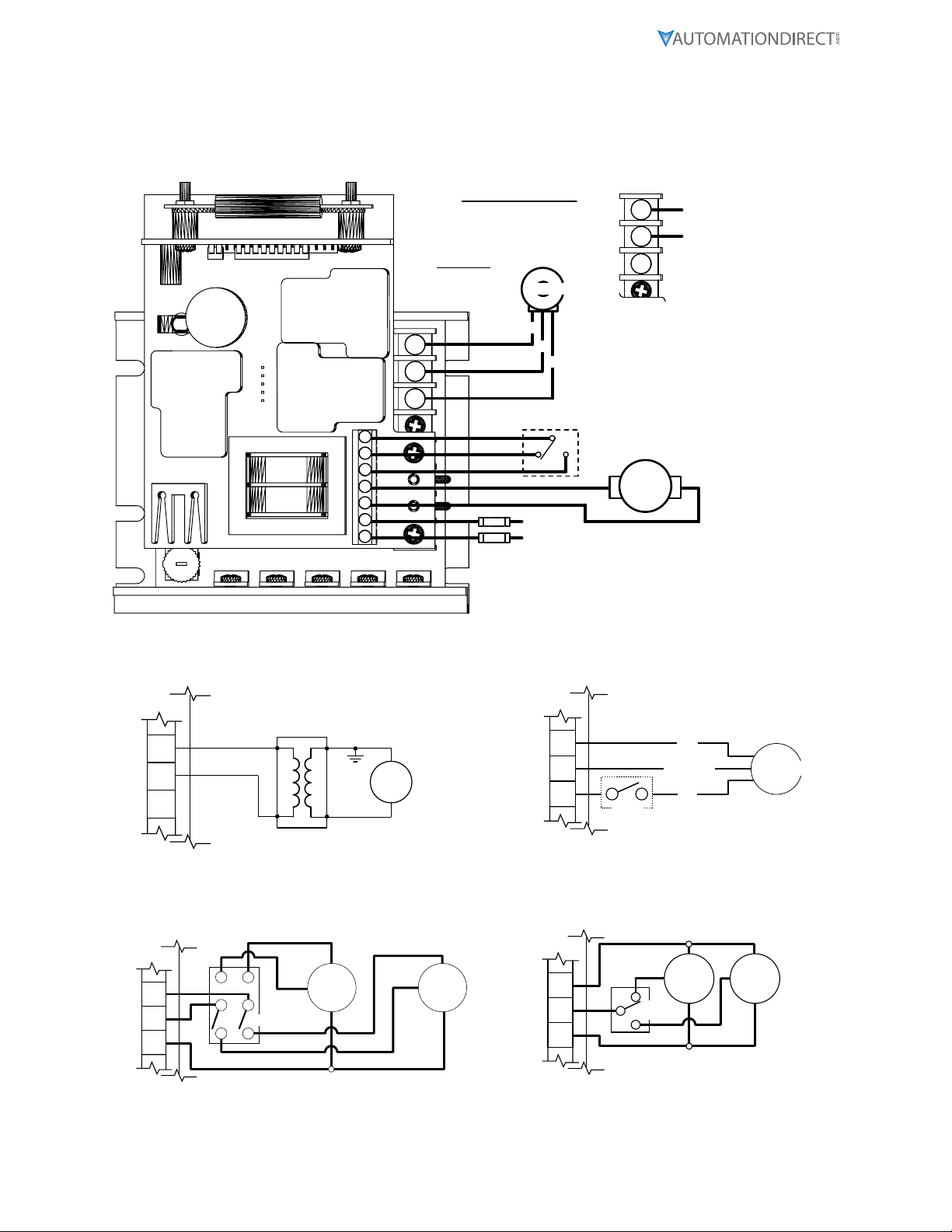
wirinG terMinal fUnCtions
GSD7 Series DC Drives – Terminal Strip Functions
CAUTION: BE SURE DRIVE HOUSING IS PROPERLY GROUNDED!
Number Purpose
P4 – Upper Terminal Block Connections
P4-1 (AC1 / L) – For AC systems with a grounded neutral line, connect the Hot (ungrounded) side of your AC line to
this terminal. For systems with two Hot AC lines, connect either of the Hot AC lines to this terminal.
P4-2 (AC2 / N) – For AC systems with a grounded neutral line, connect the Neutral (grounded) side of your AC line
to this terminal. For systems with two Hot AC lines, connect either of the Hot AC lines to this terminal.
P4-3 (A1) – For clockwise rotation of your motor in the Fwd Direction, connect the Plus (+) Armature wire of the
motor to this terminal.
P4-4 (A2) – For counter-clockwise rotation of your motor in the Rev direction, connect the Minus (-) Armature wire
of the motor to this terminal.
P4-5
(REV) – This is the reverse direction input terminal. When connected to the COM terminal, the drive will
release its brake circuit and accelerate to its set point in the reverse direction. When the connection to the
COM terminal is opened, the drive will brake to zero speed. The connection to the COM terminal can be
made via a mechanical switch, a relay contact, or an ungrounded solid-state open-collector type switch.
Switching requirements are 5VDC at less than 1mA.
P4-6
(FWD) – This is the forward direction input terminal. When connected to the COM terminal, the drive will
release its brake circuit and accelerate to its set point in the forward direction. When the connection to
the COM terminal is opened, the drive will brake to zero speed. The connection to the COM terminal can
be made via a mechanical switch, a relay contact, or an ungrounded solid-state open-collector type switch.
Switching requirements are 5VDC at less than 1mA.
P4-7 (COM) – This is the common terminal for the forward and reverse speed/dynamic brake commands.
This terminal should not be grounded or tied to any other terminal.
P1 – Lower Terminal Block Connections
P1-4
(-A/-F) – DO NOT use for Permanent Magnet Motor. This supplies -Field voltage for a SHUNT WOUND
MOTOR. For motors with dual voltage field (i.e. 50/100V or 100/200V), make sure highest value is connected.
Note: When connecting to this terminal, you will need to use a fork or ring connector placed directly under the
screw head.
P1-5 (+F) – DO NOT use for Permanent Magnet Motor. This supplies +Field voltage for a SHUNT WOUND MOTOR.
For motors with dual voltage field (i.e. 50/100V or 100/200V), make sure highest value is connected.
P1-6
(Speed pot Hi) – Connects to high side (white wire) of Speed pot (CW end). This is an internal +12VDC. For
start-stop applications, the connection between this terminal and Speed pot HI can be opened and closed by
a SPST switch. INPUT MUST NOT BE GROUNDED!
P1-7 (Speed pot Wiper) – Connects to wiper (red wire) of Speed pot (center lead). For Voltage-Follower
applications, this INPUT MUST NOT BE GREATER THAN +12V MAXIMUM AND MUST NOT BE GROUNDED!
P1-8
(Speed pot Lo) – Connects to Low side (orange wire) of 5kΩ Speed pot (CCW end). This input is raised and
lowered by the MIN trim pot (5kΩ). Electronic speed input (voltage follower) may be referenced to Speed pot
LO if the MIN trim pot adjustments are to be active. Otherwise, inputs may be referenced to -ARM, which will
bypass the MIN trim pot. INPUT MUST NOT BE GROUNDED!
ensure that the gsd7 control housing is properly grounded.
for applications using analog references other than speed pots (0 to 10v signals), the input connection to the
lo, Wiper, and hi terminals (p1-6, p1-7, and p1-8 respectively) must not be grounded! the gsd7 drive
may be damaged as the result of agrounded input!
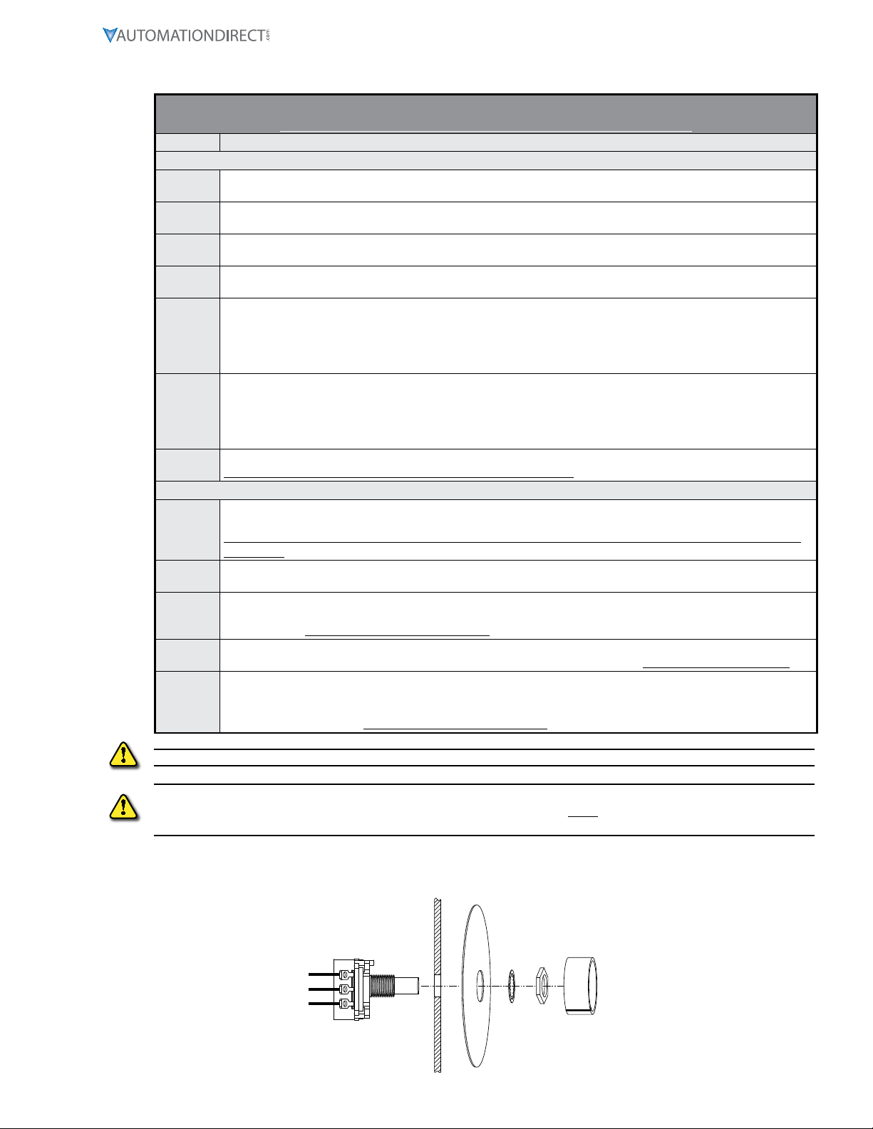
sPeeD Pot MoUntinG
CUSTOMER’S
MOUNTING BRACKET
DIALPLATE
(2-inch dia)
SPEEDPOT
KNOB
HEX NUT
LOCK
WASHER
SPEEDPOT