IronStrike CI1500DVF Owner's manual

INSTALLER: Leave this manual with the appliance.
CONSUMER: Retain this manual for future reference.
INSTALLATEUR: Laissez cette notice avec l'appareil.
CONSOMMATEUR: Conservez cette notice pour consul-
tation ultérieure.
- Donotstoreorusegasolineorotherflammablevaporsand
liquids in the vicinity of this or any other appliance.
- WHAT TO DO IF YOU SMELL GAS
phone in your building.
department.
- Installation and service must be performed by a quali-
WARNING: If the information in these instructions is
vapeurs ou liquides inflammables dans le voisinage
de cet appareil ou de tout autre appareil.
- QUE FAIRE SI VOUS SENTEZ UNE ODEUR DE GAZ:
des téléphones se trouvant dans le bâtiment où vous
trouvez.
depuis un voisin. Suivez les instructions du fournis-
seur.
appelez le service des incindies.
le fournisseur de gaz.
AVERTISSEMENT : Assurez-vous de bien suivre les
instructions données dans cette notice pour réduire
ou la mort.
INSTALLATION AND OPERATION
Ce manuel d’installation est disponible en
francais, s implement en faire la demande.
Numéro de la pièce 900186-00.
MODELS
P/N 900129-00 REV. NC 01/2014
Direct-Vent
SEREFINA™ SERIES
WARNING
AVERTISSEMENT
UNE SURFACE VITRÉE CHAUDE PEUT
CAUSER DES BRÛLURES.
LAISSER REFROIDIR LA SURFACE
VITRÉE AVANT D'Y TOUCHER.
NE PERMETTEZ JAMAIS À UN ENFANT
DE TOUCHER LA SURFACE VITRÉE.
HOT GLASS WILL
CAUSE BURNS.
DO NOT TOUCH GLASS
UNTIL COOLED.
NEVER ALLOW CHILDREN TO
TOUCH GLASS.
CI1500DVF CI2500DVF
US
Portland
OTL Report No. 116-S-08-5
P900129-00

2
CONGRATULATIONS!
When you purchased your new gas stove, you joined the ranks
of thousands of individuals whose answer to their home heat-
ing needs reflects their concern for aesthetics, efficiency and
our environment. We extend our continued support to help you
achieve the maximum benefit and enjoyment available from your
new gas stove.
Thank you for selecting an Innovative Hearth Products LLC (IHP)
gas stove as the answer to your home heating needs.
TABLE OF CONTENTS
Using this Manual ...................................................... 2
Safety and Warning Information....................................3-4
Homeowner - Attaching Safety In Operation Warnings ........... 5
General Information ................................................... 6
Introduction ............................................................. 7
Location ................................................................. 7
................................... 8
Smoke Detectors........................................................ 8
The Gas Stove ........................................................... 8
Codes and Approvals................................................... 8
Commonwealth Of Massachusetts Requirements ................. 8
...................................... 8
Pre-Installation...................................................... 9-13
Features......................................................... 9
Packaging List ................................................. 9
Ratings .......................................................... 9
................................10
Clearances to Combustibles ................................11
............12
..........................12
Vent Termination Clearances ...........................12-13
Installation..........................................................14-25
Typical Installation Sequence .............................14
Detailed Installation Steps .................................14
Step 1 Preparation ..........................................14
Step 2 Remove Packaging ..................................14
Step 3 Remove Stove From Pallet ........................14
USING THIS MANUAL
Please read and carefully follow all of the instructions found in this
manual. Please pay special attention to the safety instructions provided
in this manual.
PRODUCT IS SUBJECT TO CHANGE WITHOUT NOTICE
Step 4 Remove Front Glass ................................15
Step 5 Remove Firebox Contents ..........................15
Step 6 Remove Cardboard Packaging ....................15
Step 7 Install LP Conversion / Options ...................15
Step 8 Install Lower Access Door .........................16
Step 9 Install Venting .......................................16
Step 10 Connect Gas Line ..................................20
Step 11 Install Log Set ......................................20
Step 12 Reinstall Front Glass ..............................22
Step 13 Perform Leak Test .................................22
Step 14 Check Appliance Operation .......................23
......................................23
......................24
Step 17. Attaching Safety-in-Operation Warnings .....24
Operation And Care Of Your Appliance .............................25
Gas Controls ..................................................25
Control Compartment Access ..............................25
........................25
Burn-In Period ................................................25
Front Glass Enclosure Panel ...............................26
Maintenance ..................................................27
Wiring Diagrams .............................................28
.............................29
.............................30
Rating Labels .................................................31
Maintenance Schedule ......................................32
Troubleshooting ..............................................33
Replacement Parts List .................................34-36
Accessories ...............................................37-39
Warming Shelves - Installation Instructions ......................40
Warranty ................................................................41
Product Reference Information ......................................42

3
IMPORTANT SAFETY AND WARNING
INFORMATION
WARNING
Youngchildrenshouldbecarefullysupervisedwhen
they are in the same room as the appliance. Tod-
to accidental contact burns. A physical barrier is
recommended if there are at risk individuals in the
young children and other at risk individuals out of
the room and away from hot surfaces.
AVERTISSEMENT
-
contact avec la surface chaude. Il est recommandé
WARNING
-
damage. Refer to this manual. For assistance or
service agency or the gas supplier.
WARNING
Failure to comply with these installation instructions
will result in an improperly installed and operating
appliance and/or its operating controls is dangerous.
WARNING
Clothing or other flammable material should not
be placed on or near the appliance.
AVERTISSEMENT
WARNING
Any safety screen or guard removed for servicing
the appliance must be replaced prior to operating
the appliance.
AVERTISSEMENT
Tout écran ou protecteur retiré pour permettre
WARNING
Improper installation or use of this appliance can
explosion or carbon monoxide poisoning.
WARNING
Children and adults should be alerted to the hazards
of high surface temperature and should stay away to
avoid burns or clothing ignition.
AVERTISSEMENT
des dangers que posent les températures de surface
WARNING
DO NOT ATTEMPT TO ALTER OR MODIFY THE CON-
STRUCTION OF THE APPLIANCE OR ITS COMPO-
NENTS. ANY MODIFICATION OR ALTERATION MAY
OF THIS UNIT.

4
FORYOURSAFETYdonotinstalloroperatethisappliancewithout
operation of the appliance deviating from that which is stated
in this manual WILL void the warranty and may be hazardous.
INSTALLATIONANDREPAIRSHOULDONLY BE DONE BY
A QUALIFIED SERVICE TECHNICIAN. DO NOT ATTEMPT
TO SERVICE THE APPLIANCE YOURSELF.
Do not make any make-shift compromises during installation.
-
listings of this unit.
-
niques and construction materials or practices other than those
limited warranty.
This gas appliance must be equipped for the proper fuel type
and altitude at which it will be operated. Any operation outside
the parameters outlined in this manual may result in a hazard-
ous condition and will void the warranty. Please carefully read
appliance is properly equipped.
prior to operating the appliance. Do not operate the appliance
Plated surfaces must be cleaned with glass cleaner and a clean
this will remove the plating!!!
When opening the lower door on the face while the appliance is
the door is hot during operation.
-
installé dans un endroit où il y a peu de circulation et loin du
mobilier et des tentures.
Provide adequate clearances around air openings and adequate
accessibility clearance for service and proper operation. Never
obstruct the front openings of the appliance.
These appliances are designed to operate on natural or propane
gas only. The use of other fuels or combination of fuels will de-
grade the performance of this system and may be dangerous.
Theseappliances aredesignedassupplementalheaters.There-
when installed in a dwelling.
These appliances must not be connected to a chimney or flue
serving a separate solid fuel burning appliance.
These appliances are vented gas appliances. Do not burn wood
or other material in these appliances.
This appliance is only for use with the type of gas indicated on
rating plate. This appliance is not convertible for use with other
indiqués sur la plaque signalétique. Ne pas l'utiliser avec
Hot while in operation. Do not touch. Severe Burns may result.
having flammable vapors away.
not prohibited by local codes.
permettent.
Ensure clearances are in accordance with local installation
codes and the requirements of the gas supplier.
Dégagement conforme aux codes d'installation locaux et aux
exigences du foumisseunde gaz.
person. The appliance should be inspected before use and at
least annually by a professional service person. More frequent
cleaning may be required due to excessive lint from carpet-
appliance be kept clean.
Do not use this appliance if any part has been under water.
appliance and to replace any part of the control system and any
gas control which has been under water.
-
the installation of this appliance.
Seuleslestroussesde garniture fourniesparlefabricant doivent
INSTALLER: THESE INSTRUCTIONS ARE TO REMAIN WITH THE
HOME OWNER!

5
APPOSITION DES MISES EN GARDE RELATIVES
Il est impératif que les étiquettes de sécurité fournies
avec le foyer soient collées à côté des dispositifs
de contrôle du foyer. Une étiquette de sécurité doit
être collée sur la plaque de l’interrupteur contrôlant
l’allumagedufoyer(voir FigureA)ousurlethermostat
mural (voir Figure B)et, le cas échéant, sur le boîtier
de la télécommande (Figure C). Les mises en garde
auraientdûêtrecolléesaumomentdel’installationinitiale
du foyer. Si ce n’est pas le cas, prenez les étiquettes
adhésives multilingues fournies avec ces instructions
et procédez comme suit:
1. Repérez l’interrupteur ou le thermostat mural
qui contrôle le foyer (vérifiez que l’interrupteur
contrôle le fonctionnement du foyer en le faisant
basculerde MarcheàArrêt, etvice-versa). Nettoyez
soigneusement la plaque murale de l’interrupteur
ou le thermostat mural pour éliminer la poussière
et les traces de graisse ou d’huile. Collez l’étiquette
sur la surface de la plaque de l’interrupteur mural
qui contrôle le foyer (Figure A)ou du thermostat
mural (Figure B). Choisissez la langue qui est
principalement parlée dans la résidence du
propriétaire. En cas de doute, collez l’étiquette en
anglais.
2. Si une télécommande est utilisée pour contrôler
le foyer, nettoyez la soigneusement pour éliminer
la poussière et les traces de graisse ou d’huile.
Collez l’étiquette sur le boîtier de la télécommande
(Figure C). Choisissez la langue qui est principale-
ment parlée dans la résidence du propriétaire. En
cas de doute, collez l’étiquette en anglais.
3. Si vous ne trouvez pas les étiquettes, veuillez
appeler IHP ou votre distributeur IHP local pour
recevoirgratuitementdesétiquettessupplémentaires.
Étiquettes de remplacement, n° cat. H8024
IHP
www.IronStrike.us.com
Remarque : Le texte anglais est rouge sur un support
transparent. Le texte français et espagnol est blanc
sur un support noir.
COLOCACIóNDE ADVERTENCIASDESEGURIDAD
EN OPERACIóN
Se requiere que las etiquetas de instrucciones de
seguridad incluidas con la chimenea se coloquen en
el punto de operación y control de la misma. Se debe
colocar una etiqueta de instrucciones de seguridad
en la placa del interruptor de pared desde el cual se
enciende y se apaga la chimenea (ver la Figura A)o
en el termostato de pared (ver la Figura B)y en el
transmisor de control remoto (Figura C)si se usa.
Las advertencias ya deben haberse colocado cuando
se completó la instalación inicial de la chimenea. Si
no están colocadas en estos lugares, encuentre las
etiquetas adhesivas multilingües proporcionadas con
estas instrucciones y prosiga de la siguiente manera:
1. Identifique el interruptor o el termostato de pared
quecontrolalachimenea(verifiquequeelinterruptor
opera la chimenea encendiéndola y apagándola).
Limpiebienlaplacadelinterruptoroeltermostatode
pared para quitar el polvo y aceite. Pegue la etiqueta
enlasuperficiedelaplacadelinterruptorquecontrola
la chimenea (Figura A)o en el termostato de pared
(Figura B).Seleccione el idioma que más se habla
en la casa. Si no sabe cuál es, use la etiqueta en
inglés.
2. Si se usa un control remoto para controlar la
chimenea, encuentre el transmisor y límpielo bien
para quitar el polvo y aceite. Pegue la etiqueta en
la superficie del transmisor (Figura C).Seleccione
el idioma que más se habla en la casa. Si no sabe
cuál es, use la etiqueta en inglés.
3. Si nopuede encontrarlas etiquetas,sírvase llamara
IHPo aldistribuidordeIHPmáscercanopararecibir
etiquetasde instruccionesde seguridadadicionales
gratuitas.
Juego de etiquetas de repuesto - Nº de cat. H8024
IHP
www.IronStrike.us.com
Nota: La etiqueta en inglés es transparente con texto
rojo. Las etiquetas en francés y español son negras
con texto blanco.
ATTACHING SAFETY IN OPERATION WARNINGS
It is required that the safety instruction labels fur-
nished with the fireplace be affixed to the operation
andcontrolpointofthefireplace. Asafetyinstruction
label must be affixed to the wall switch plate where
the fireplace is turned on and off (See Figure A)or
wall thermostat (See Figure B)and if used on the
remote control handheld transmitter (Figure C).
The warnings should already have been put in place
when the fireplace initial set-up was completed.
If they are not affixed at these spots, locate the
multi-lingual adhesive labels provided with these
instructions and proceed as follows:
1. Locate the wall switch or wall thermostat that
controlsthefireplace (verifythe switch operates
the fireplace by turning it on and off). Clean the
wall switch plate or wall thermostat thoroughly
to remove any dust and oils. Affix the label to
the surface of the plate of the wall switch that
controls the fireplace (Figure A)or the wall
thermostat (Figure B). Choose the language
primarily spoken in the home. If unknown, affix
the English language label.
2. Ifaremotecontrolisusedtocontrolthefireplace,
locate the transmitter and clean it thoroughly
to remove any dust and oils. Affix the label to
the surface of handheld transmitter (Figure C).
Choose the language primarily spoken in the
home. If unknown, affix the English language
label.
3. If you are unable to locate the labels, please
contactIHP oryour nearestIHP dealertoreceive
additionalsafetyinstructionlabelsfreeofcharge.
Cat. No. H8024 Replacement Label Kit
IHP
www.IronStrike.us.com
NOTE: English is red text on clear label. French
and Spanish are white text on black label.
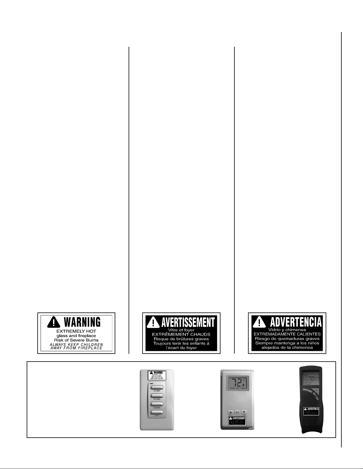
ATTACHING SAFETY-IN-OPERATION WARNING LABELS
SAFETY LABEL
DIAGRAMS
DIAGRAMAS DE ETIQUETAS
DE SEGURIDAD
DIAGRAMMES DES ÉTIQUETTES
DE SÉCURITÉ
Figure A Figure B Figure C
Illustrations are for example only.
Your accessories may be different.
Les illustrations sont par exemple
uniquement. Vos accessoires
peuvent être différents.
Las ilustraciones son sólo ejemplos.
Tu accesorios pueden ser diferentes.

6
GENERAL INFORMATION
Models Natural Gas Propane
CI1500DVF
CI2500DVF
Table 1
NOTE: Installation and repair should be performed by a qualified
service person. The appliance should be inspected annually by a
qualified professional service technician. More frequent inspections
and cleanings may be required due to excessive lint from carpeting,
bedding material, etc. It is imperative that the control compartment,
burnersandcirculatingairpassagewaysoftheappliancebekeptclean.
S'assurer que le brùleur et le compartiment des commandes sont
propres. Voir les instructions d'installation et d'utilisation qui
accompagnent l'appareil.
Provideadequateclearancesaroundairopeningsandadequateacces-
sibility clearance for service and proper operation. Never obstruct the
front openings of the appliance.
These appliances are designed to operate on natural or propane
gas only.
These millivolt models come standard with the manually-modulated
gas valve; flame appearance and heat output can be controlled at
the gas valve.
Theseappliancesaredesignedassupplementalheaters.Therefore,itis
advisabletohave analternateheat sourcewhen installedina dwelling.
Table 1 shows the BTU input for each model:
Installations at Altitudes of 0 to 4500 feet - Units are tested and
Installations at Altitudes above 4500 ft.-
according to the regulations of the local authorities having
CAN/CGA-B149.1 and CAN/CGA-B149.2 codes.
Table 4
Tables 2 and 3 show the units' gas pressure requirements:
Inlet Gas Supply Pressure
Fuel # Minimum Maximum
Natural Gas
Propane
Table 2
Manifold Gas Supply Pressure
Fuel # Low High
Natural Gas
Propane
Table 3
The millivolt appliances are manually controlled and feature a spark
use of matches or batteries. This system provides continued service
in the event of a power outage.
Do not use these appliances if any part has been under water. Imme-
the appliance and to replace any parts of the control system and any
gas controls which have been under water.
-
commande qui ont été plongés dans l'eau.
This appliance may be installed in an aftermarket permanently
not prohibited by local codes.
locaux le permettent.
Test gauge connections are provided on the front of the millivolt gas
control valve (identified IN for the inlet and OUT for the manifold side).
Propane tanks are at pressures that will cause damage to valve com-
ponents. Verify that the tanks have step down regulators to reduce the
pressure to safe levels.
Model
No.
Natural
Gas
Propane
Gas
Elevation
CI1500DVF
CI2500DVF .121"
Table 4
These appliances must not be connected to a chimney or flue serv-
ing a separate solid fuel burning appliance.
The appliance must be isolated from the gas supply piping system
by closing its equipment shutoff valve during any pressure testing of
the gas supply piping system at test pressures equal to or less than
1/2 psig (3.5 kPa).
The appliance and its appliance main gas valve must be disconnected
from the gas supply piping system during any pressure testing of that
system at test pressures in excess of 1/2 psig (3.5 kPa).

7
WARNING
Failuretocomplywiththeinstallationandoperating
instructions provided in this document will result in
voiding its warranty. Any change to this appliance
and/oritsoperatingcontrolsisdangerous. Improper
installation or use of this appliance can cause seri-
carbon monoxide poisoning.
WARNING: This appliance must be properly connected to a venting
system. Operation of this gas appliance when not connected to
a properly installed and maintained venting system can result in
Carbon Monoxide Poisoning: Early signs of carbon monoxide
be operating correctly. Some people are more affected by carbon
WARNING
Youngchildrenshouldbecarefullysupervisedwhen
they are in the same room as the appliance.
NOTE: An Optional Screen Panel for the glass is avail-
able(seeAccessorysectionfororderinginformation).
LOCATION
INTRODUCTION
In selecting the location, the aesthetic and functional use of the
appliance are primary concerns. However, vent system routing to the
exterior and access to the fuel supply are also important. Consider-
ation should be given to traffic ways, furniture, draperies, etc., due
to elevated surface temperatures.
Considerations Should Include:
• Existing Chimneys
• Aesthetic Considerations
• Roof Design (Rafter Locations and Roof Pitch)
• Room Traffic
• Proximity to Combustibles
• Proximity for Optimum Heat Transfer
• Electrical Wiring (if optional blower is installed)
The installation of this stove will require some research. Once your
options are determined, consult with your local building department
who will be able to give you the necessary installation requirements for
your area (Is a building permit required?, Rooms where installation may
not be allowed?, etc.).
The stove models covered in this manual are Direct-Vent sealed
combustion vented gas stove heaters designed for residential and
manufactured home applications. Direct-Vent appliances operate
with the combustion chamber isolated from the inside atmosphere.
All air for combustion is brought in from the outside and exhaust
gases are vented through the same direct-vent, vent system.
These millivolt appliances are designed to operate on either natural or
propane gas. A millivolt gas control valve with piezo ignition system
provides safe, efficient operation. External electrical power is required
to operate the optional electrically powered components if installed.

8
• Must conform with all local, state and national installation codes.
In the absence of local codes, the installation must conform with
(USA) National Fuel Gas Code NFPA 54/ANSI Z223.1 - latest edition
or, in Canada, the CAN/CGA-B149.1 codes - latest edition. Refer to
the National Fuel Gas Code and local zoning and code authorities for
details on installation requirements.
• Manufactured home installations (USA only) must conform with the
Manufactured Home Construction and Safety Standard, Title 24 CFR,
Part 3280, or, when such a standard is not applicable, the Standard for
ManufacturedHomeInstallations, ANSI/NCSBCSA225.1, orStandard
for Gas Equipped Recreational Vehicles and Mobile Housing, CSA
Z240.4.
• Must be vented directly to the outside in accordance with the latest
edition of the National Fuel Gas Code and must never be attached to
a chimney or flue serving a separate solid fuel burning appliance.
• Has been certied for use with either natural gas or propane.
• Is not for use with solid fuels.
• Is approved for sitting rooms and/or bedrooms.
THE GAS STOVE
ORIFICE SIZE/ALTITUDE ADJUSTMENT
For altitudes above 4,500 FT (1370 M), the orifice should be de-rated by
4% for every 1,000 feet to maintain the proper ratio of gas to air. Improper
orifice sizing may result in damage and unsafe conditions. Changing the
orifice should only be done by a qualified service technician. Contact your
IHP dealer for proper orifice sizes (see Page 6 for more information).
Install the unit according to the regulations of the local authorities having
jurisdiction and, in the USA, the latest edition of the National Fuel Gas
Code (ANSI Z223.1) or, in Canada, the latest edition of the CAN/CGA-
B149.1 and B149.2 codes.
-
AUTHORITIES HAVING JURISDICTION AND IN ACCORDANCE WITH
THE REQUIREMENTS OF THE CAN/CGA-B149.1 OR CAN/CGA-B149.2
INSTALLATION CODES.
SMOKE DETECTORS
Since there are always several potential sources of fire in any home, we
recommend installing smoke detectors. If possible, install the smoke
detector in a hallway adjacent to the room (to reduce the possibility of
occasional false activation from the heat produced by the appliance). If
your local code requires a smoke detector be installed within the same
room, you must follow the requirements of your local code. Check with
your local building department for requirements in your area.
Installation of these appliances are approved for installation in New York
City in the US state of New York.
CODES AND APPROVALS
Gas appliances must be tested and certified by a nationally recognized
testing and certification laboratory to ANSI (American National Standard
Institute) gas appliance safety standards.
These appliances comply with National Safety Standards and are tested
and listed by OMNI-Test Laboratories Inc.; Portland, Oregon (Report No.
116-S-08-05)toANSIZ21.88(in Canada,CSA-2.33),andCAN/CGA-2.17-
M91 in both USA and Canada, as vented gas heaters.
It has met all necessary ANSI Standards and is fully certified for installa-
tion in any community. If there are any questions or if you need further
substantiation either write to or call your IHP dealer. If you have further
questions, please contact IHP.
Check all local building and safety codes before installation. The instal-
lation instructions and appropriate code requirements must be followed
exactly and without compromise. In the absence of local codes the fol-
lowing standards and codes must be followed.
The Installation must conform with local codes or, in the absence of local
codes, with the (USA) National Fuel Gas Code NFPA 54/ANSI Z223.1 -
latest edition or, in Canada, the CAN/CGA-B149.1 codes - latest edition.
The appliance, when installed, must be electrically grounded and wired
in accordance with local codes or, in the absence of local codes, with the
National Electrical Code, ANSI/NFPA 70 - latest edition, or the Canadian
Electrical Code, CSA C22.1 - latest edition.
COMMONWEALTH OF MASSACHUSETTS REQUIREMENTS
These appliances are approved for installation in the US state of Mas-
sachusetts if the following additional requirements are met:
• Install this appliance in accordance with Massachusetts Rules and
Regulations 248 C.M.R. Sec. 5.08 2(a) through 2(e).
• Installation and repair must be done by a plumber or gas tter licensed
in the Commonwealth of Massachusetts.
• The exible gas line connector used shall not exceed 36 inches (92
centimeters) in length.
• The individual manual shut-off must be a T-handle type valve.
Massachusetts Horizontal Vent Requirements
IntheCommonwealthofMassachusetts,horizontalterminationsinstalled
less than seven (7) feet above the finished grade must comply with the
following additional requirements:
• A hard wired carbon monoxide detector with an alarm and battery
back-up must be installed on the floor level where the gas fireplace
is installed. The carbon monoxide detector must comply with NFPA
720, be ANSI/UL 2034 listed and be ISA certified.
• A metal or plastic identication plate must be permanently mounted to
the exterior of the building at a minimum height of eight (8) feet above
grade and be directly in line with the horizontal termination. The sign
must read, in print size no less than one-half (1/2) inch in size, GAS
VENT DIRECTLY BELOW. KEEP CLEAR OF ALL OBSTRUCTIONS.

9
* Other approved chimney brand is Simpson Dura-Vent DV-GS.
PRE-INSTALLATION
RATINGS
CI1500DVF CI2500DVF
NATURAL GAS LP GAS NATURAL GAS LP GAS
Max/Min Input BTUh 0-4500 FT/0-1370 M u
3.5 10.0 3.5 10.0
4.5 11 4.5 11
w
67% 65% 67% 64%
v
85% 87% 83% 85%
O
0-4500 FT/0-1370 M u
uUnit factory equipped for 0-4500 FT/0-1370 M elevation.
v
w
FEATURES
Installation Options
Residential
Top Vent - vertical or horizontal termination
Manufactured (mobile) home
Natural gas (NG) or propane (LP)
Bedrooms
Optional wall-mounted or remote thermostat
Venting
This appliance can be vented with Secure Vent®direct-vent pipe. Coaxial
pipe diameters are 6-5/8” outer and 4” inner. The combustion air for this
stove is drawn from outside the house through the outer DV (direct-vent)
pipe. Room air is not required for combustion.
When planning your installation, select the correct length of vent pipe
for your particular requirements. Determine the minimum clearance to
combustibles from the rear of the unit to the wall. It is also important
to note the thickness of the wall. Before cutting the vent hole through
the wall make sure that ALL vent and termination clearances (see Page
8) will be met.
Electrical
The optional blower requires 120 Volts AC for operation. The stove is
not dependent on the blower or an outside electrical supply to operate.
WARNING - Electrical Grounding Instructions - This appliance
-
tection against shock hazard and should be plugged directly
into a properly grounded three-prong receptacle. Do not cut or
remove the grounding prong from this plug.
Millivolt Valve
This appliance is operated with a millivolt valve and therefore burns
during a power outage.
Fuel
This appliance comes from the factory equipped to burn natural gas at a
specified elevation. The appliance can be converted to burn LP gas (liquid
propane) by installing a natural gas to propane conversion kit (provided).
Only IHP conversion kits can be used to convert from NG to LP or LP to
NG. Contact your IHP dealer for details.
Pipe:Type - direct-vent
Recommended manufacturer*
Secure Vent®by IHP*
Diameter - 6-5/8” x 4” for all installations
Stove Packaging List
one - log set located in firebox
one - ember strip located beneath stove body (on pallet)
one - bag of glowing embers located in the firebox
one - envelope containing the literature package which consists of the
installation and operation manual and warranty; located on the
top of the firebox
one - cast iron top
one - trivet
one - natural gas to propane conversion kit
one - ash lip
one - lower access door
four - leg levelers
Options
• Wall-Thermostat, Switch or Timer
• Remote Control
• Blower Kit
• Firebox Liner Kits
• Warming Shelves
• Firescreen Kits

10
Figure 1
H
(with optional warming shelves)
F
E
(with ashlip)
A
B
D
L E N N O X
G
C
Dimensions
CI1500DVF CI2500DVF
A
B
C
D
E
F
G
H
CI1500DVF CI2500DVF
Min./Max
BTU/hr Input - NG
Min./Max
BTU/hr Input - LP
DV Vent Size
Room Fan CFM 150 150
206 290
CI1500DVF CI2500DVF
EnerGuide P4
Steady State
Diagrams, illustrations and photographs are not to scale – consult installa-
tion instructions. Product designs, materials, dimensions, specifications,
colors and prices are subject to change or discontinuance without notice.

11
Top View / Corner Clearances
Top View / Rear Wall or Alcove Clearances
Side View / Rear Wall or Alcove Clearances
Clearance To Combustibles and Alcove Dimensions
Figure 2C
Clearances To Combustible Materials / Floor Protection
• The location should also be free of electrical, plumbing or other
heating/air conditioning ducting.
• Due to high temperatures, this appliance should be located out
of traffic and away from furniture, draperies and not in windy or
drafty areas.
• This appliance can be installed in most residential room congura-
tions, parallel to a rear or adjacent wall, or in an alcove that allows
for the minimum clearances to combustible surfaces. Your local
building inspector should review your plans prior to installation.
• When installing this appliance, provide adequate clearances for
the purposes of servicing and proper operation.
• Asdeterminedthroughthesafetycertificationofthisunit,aminimum
clearance to combustible materials must be maintained around
specific areas of the gas appliance. (See Table 5 and Figures 2A,
2B and 2C).
Clearances
CI1500DVF CI2500DVF
Table 5
required as follows:
above the appliance.
NOTE: Recommended clearance zone from the front of the appliance to com-
bustibles is 36 inches (914 mm) minimum.
Floor Protection
When installed directly on carpeting, tile (see Note below) or other
combustible material other than wood flooring, the appliance shall
be installed on a metal or wood panel extending the full width and
depth of the stove body.
NOTE: Ceramic tile is non-combustible and does not require a wood
or metal panel under the appliance.
Vent Clearances - All Models
For Horizontal Sections:.................At Wall Firestops:
Top - 3" (76.2 mm) min. ............Top - 3" (76.2 mm) min.
Sides - 1" (25.4 mm) min. .........Sides - 1" (25.4 mm) min.
Bottom - 1" (25.4 mm) min........Bottom - 1/2" (12.7 mm) min.
For Vertical Sections:
Sides - 1" (25.4 mm) min.
Figure 2B
Figure 2A
H
D
*A
GJ
L E N N O X
*B
D
EE
I
F
F
*C
MINIMUM CLEARANCES TO COMBUSTIBLES

12
QUESTIONS TO ASK LOCAL BUILDING OFFICIAL
These models may be installed in an aftermarket permanently
located, manufactured home, where not prohibited by local codes.
When installed in Manufactured Housing the following supplemental
requirements must be met:
• The appliance must be secured to the oor (i.e. use (4) 1/4" x 2-3/4"
bolts and nuts or equivalent. NOTE: Not included) for securing appli-
ance to the manufactured home floor.
• The appliance must be grounded to the chassis of the manufactured
home. Use a No. 8 or heavier copper wire at least 18” in length.
• The structural integrity of the manufactured home oor, walls, ceiling
and roof must be maintained.
• A manufactured (mobile) home installation must conform with the
Manufactured Home Construction and Safety Standard, Title 24 CFR,
Part 3280, or, when such a standard is not applicable, the Standard
for Manufactured Home Installations, ANSI / NCSBCS A225.1, or
standard for Gas equipped Recreational Vehicles and Mobile Housing,
CSA Z240.4.
This appliance must be installed per manufacturers’ instructions.
Installationsmustconformtoappropriatelocalcodesandapplicablestate
and federal requirements. Familiarity with these requirements before
installation is essential. Some important considerations to discuss with
local building officials include:
1. Applicable codes (i.e. Uniform Mechanical Code, State or Regional
Gas Codes, National Fuel Gas Code)
2. Local amendments
3. Recognizedtestinglab:OMNI-TestLaboratoriesInc.;Portland,Oregon
4. Is a permit required - cost?
5. In some states or municipalities, a licensed gas fitter or plumber may
be required to install this appliance. Check with your local building
official for requirements in your area (i.e. Is a license required for
installation of gas supply line)?
6. Maximum amount of gas pipe without a pressure test - type of test
required?
7. Are below grade penetrations of the gas line allowed?
8. Is concealed gas piping allowed?
9. Specific requirements of concealed fittings?
10.Is rigid pipe to appliance required?
11.Allowed piping materials?
12.Shut-off valve required within 4 feet of the firebox?
13.May the shut-off valve be concealed?
14.Rooms where the installation is not allowed?
In the absence of local codes, installation should conform to National
Fuel Gas Code, ANSI Z223.1 / NFPA 54-Latest Edition in the USA or
National Fuel Gas Code, CAN/CGA-B149.1-Latest Edition in Canada.
12
X
Roof Pitch is X/12
2 FT
MIN.
2 FT MIN.
Lowest
Discharge
Opening
H*
*H = MINIMUM HEIGHT FROM ROOF TO
LOWEST DISCHARGE OPENING OF VENT
TERMINATION HEIGHTS FOR VENTS ABOVE
FLAT OR SLOPED ROOFS
Horizontal Overhang
Vertical
Wall
Vent
Termination
Storm Collar
Concentric
Vent Pipe
Flashing
1 inch (25.4 mm) Minimum
Clearance to Combustibles
The vent/air intake termination clearances
above the high side of an angled roof is as
follows:
Roof Pitch..................Feet Meters
Flat to 6/12 ................1.0 0.3
6/12 to 7/12............... 1.25 0.38
7/12 to 8/12............... 1.5 0.46
8/12 to 9/12............... 2.0 0.61
9/12 to 10/12............. 2.5 0.76
10/12 to 11/12........... 3.25 0.99
11/12 to 12/12........... 4.0 1.22
12/12 to 14/12........... 5.0 1.52
14/12 to 16/12........... 6.0 1.83
16/12 to 18/12........... 7.0 2.13
18/12 to 20/12........... 7.5 2.29
21/12 to 21/12........... 8.0 2.44
Figure 4
Figure 3
Vertical Vent Termination Clearances
Theseinstructions shouldbeusedasaguidelineanddonot supersede
local codes in any way. Install vent according to local codes, these
instructions, the current National Fuel Gas Code (ANSI-Z223.1) in
the USA or the current standards of CAN/CGA-B149.1 in Canada.
Horizontal Vent Termination Clearances
The horizontal vent termination must have a minimum of 3" (76 mm)
clearance to any overhead combustible projection of 2-1/2" (64 mm)
or less. See Figure 4. For projections exceeding 2-1/2" (64 mm), For
additional vent location restrictions refer to Figure 5.
Side Elevation View
3"
(76 mm)
12"
(305 mm)
Horizontal T
Combustible Projection
greater than 2 1/2 inches in length
Horizontal Vent Termination Clearances
Combustible Projection
2 1/2 inches or less in length
18"
(457 mm)
Ventilated
Soffit Unventilated
Soffit
ermination Kit
3"
(76 mm)
1"
(25 mm)
Note - See vent manufacturer's instructions for recess
termination caps.
VENT TERMINATION CLEARANCES

13
Exterior Horizontal Vent Termination Clearance Requirements
V
V V
V
V
F
C
B
B
A
B
H
M
I
X V
D
V
A A
A
V
L
B
J
X E
V
A
G
*18”
18”
B
C
C
C
K
X
Center Line
of Termination
Exterior Wall
Horizontal
Termination
Inside Corner
DETAIL D
Minimum Clearances
A = Clearance above grade, veranda, porch, deck
or balcony.
12 inches (30 cm) * 12 inches (30 cm) **
B = Clearance to window or door that may be opened. 6 in. (15.2 cm) for appliances < 10,000 BTU/hr (3kW),
12 in. (30 cm) for appliances > 10,000 BTU/hr (3kW) and <
100,000 BTU/hr (30kW), 36 inches (91 cm) for appliances
> 100,000 BTU/hr (30kW)*
6 in. (15.2 cm) for appliances < 10,000 BTU/hr (3kW),
9 in. (23 cm) for appliances > 10,000 BTU/hr (3kW) and <
50,000 BTU/hr (15kW), 12 inches (30 cm) for appliances
> 50,000 BTU/hr (15kW)*
C = Clearance to permanently closed window 12 inches (305 mm) recommended to prevent window
condensation
9 inches (229 mm) recommended to prevent window
condensation
D = Vertical clearance to ventilated soft located
above the terminal within a horizontal distance of
18 in. (458 mm) from the center line of the terminal
18 inches (458 mm) 18 inches (458 mm)
E = Clearance to unventilated soffit 12 inches (30 cm) 12 inches (30 cm)
F = Clearance to outside corner 5 inches (12.7 cm) 5 inches (12.7 cm)
G = Clearance to inside corner 6 in. (15 cm) 6 in. (15 cm)
H = Clearance to each inside of center line extended
above meter / regulator assembly
3 feet (91 cm) within a height of 15 feet above the meter /
regulator assembly *
3 feet (91 cm) within a height of 15 feet above the meter
/ regulator assembly **
I = Clearance to service regulator vent outlet 3 feet (91 cm) * 3 feet (91 cm) **
J = Clearance to non-mechanical air supply inlet
to building or the combustion air inlet to any other
appliance
6 in. (15.2 cm) for appliances < 10,000 BTU/hr (3kW), 12
in. (30 cm) for appliances > 10,000 BTU/hr (3kW) and <
100,000 BTU/hr (30kW), 36 inches (91 cm) for appliances
> 100,000 BTU/hr (30kW)*
6 in. (15.2 cm) for appliances < 10,000 BTU/hr (3kW), 9
in. (23 cm) for appliances > 10,000 BTU/hr (3kW) and <
50,000 BTU/hr (15kW), 12 inches (30 cm) for appliances
> 50,000 BTU/hr (15kW)*
K = Clearance to mechanical air supply inlet 6 feet (1.8 meters) * 3 feet(91 cm) above,if within 10feet (3m) horizontally**
L = Clearance above paved sidewalk or paved
driveway located on public property
7 feet (2.13 m) ‡ 7 feet (2.13 m) ‡
M = Clearance under veranda, porch, deck or
balcony
12 in. (30 cm) * ‡ 12 in. (30 cm) ** ‡
* In accordance with the current CAN/CGA-B149.1 National Gas and B149.2 Propane Installation Code - Latest Editions.
** In accordance with the current ANSI Z223.1 / NFPA 54 National Fuel Codes - Latest Edition.
‡ A vent shall not terminate directly above a sidewalk or paved driveway which is located between two single family dwellings and serves both dwellings.
*‡ Only permitted if veranda, porch, deck or balcony is fully open on a minimum 2 sides beneath the floor.
Inside
Corner Detail
Operable
Window
Fixed
Closed
Window
= 9" in U.S.
= 12" in Canada
3 ft.
3 ft.
= Air Supply Inlet = Vent Terminal = Area where Terminal is NOT permitted
Figure 5

14
Remove the screws and support plate which secure the stove legs to
the pallet. Lift stove off of the pallet and place it into position (where
unit is to be installed).
the limited warranty.
Step 2: REMOVE PACKAGING - Remove the large outer carton.
Remove all the inner packages and packing materials and set aside.
To remove the ember strip package below the stove body, carefully
cut the 2 plastic ties using scissors.
Step 3: REMOVE FROM PALLET - A. Remove the trivet, then the cast
iron stove top by carefully lifting them up and off and setting them aside
(READ CAUTION BELOW).
CAUTION
The cast iron stove top is very heavy and may require a
CAUTION
The stove body is very heavy. The use of a heavy duty
lifting the stove body.
See the page numbers references in the following steps for detailed
procedures.
The typical sequence of installation follows, however, each installation is
unique resulting in variations to those described.
Step 1. (Page 14)Preparation - Plan and install gas line, venting system
and floor protection (if necessary).
Step 2. (Page 14) Remove outer carton. Remove inner packages and
packing materials and set aside.
Step 3. (Page 14)Remove stove from pallet and place into positioned
where unit is to be installed.
Step 4. (Page 15) Remove front glass enclosure from stove and set
aside.
Step 5. (Page 15) Remove packaged materials from inside firebox and
set aside (log set, bag of embers and NG to LP conversion kit).
Step 6. (Page 15) Remove cardboard packaging material from beneath
relief door and discard.
Step 7. (Page 15) Install LP Conversion kit (if necessary). Install any
optional accessories (excluding firescreens).
Step 8. (Page 16) Install lower access door.
Step 9. (Page 16)Venting System Installation.
Step 10. (Page 20)Connect gas supply line to the appliance. Purge Air.
Step 11. (Page 20) Install log set, ember strip and embers.
Step 12. (Page 22) Reinstall front glass enclosure.
Step 13. (Page 22)Test all connections for leaks (factory and field).
Step 14. (Page 23) Check appliance for proper operation.
Step 15. (Page 23)Adjust burner to ensure proper flame appearance.
Step 16. (Page 24) Install stove top, trivet and ash lip.
Step 17. (Page 25)Attach Safety-in-Operation Warnings.
Suggested Sizing of Black Iron Pipe
Schedule 40 - Pipe Supply Line
Schedule 40 Pipe
Schedule 40 Pipe
Natural
Gas
Propane
Gas
0-10 1/2 3/8
10-40 1/2 1/2
40-100 1/2 1/2
100-150 3/4 1/2
150-200 3/4 1/2
Table 6
B. Remove stove body from pallet (READ CAUTION BELOW).
TYPICAL INSTALLATION SEQUENCE
DETAILED INSTALLATION STEPS
Step 1: PREPARATION - Plan and install gas line and floor protection (if
necessary - see Floor Protection, Page 11).
Gas Supply Line (reference Figure 15 on Page 20)- Installing a gas
supply line from the fuel supply to the appliance involves numerous con-
siderations of materials, protection, sizing, locations, controls, pressure,
sediment, and more. Certainly no one unfamiliar and unqualified should
attempt sizing or installing gas piping.
The gas supply line should be plumbed from the fuel source to the
area where the appliance is to be installed per requirements outlined
in NFPA 54 - latest edition (USA) and CAN/CGA-B149.1 - latest edi-
tion (Canada).
The proper gas line diameter must be used to run from the supply
regulator (at the gas company meter) to the appliance. Never use
galvanized or plastic pipe. Refer to Table 6 for suggested sizing of
the gas supply line if black iron pipe is being used.
The gas supply line should be connected to the appliance at step 10.
WARNING
Failure to position the parts in accordance with these
approved with this appliance may result in property
AVERTISSEMENT
approuvées avec cet appareil sont utilisées.

15
NOTE: Install Leg Leveling Bolts if Necessary: The four leg leveling
bolts (included in literature package), are provided for leveling the stove
if necessary. To install, thread the bolts into the existing holes in the
bottom of each leg. Turn the leveling bolts to adjust for correct height.
Step 4: REMOVE FRONT GLASS ENCLOSURE PANEL
Remove the front glass enclosure from stove per the instructions
on Page 27.
- Remove the pack-
aged materials from inside of the firebox and set aside (propane
conversion kit, log support cartons, log set and embers).
Step 6: REMOVE CARDBOARD - Remove the cardboard packaging
material from beneath the relief door and discard (see Figure 6).
CAUTION: Label all wires prior to disconnection when servic-
ing controls. Wiring errors can cause improper and dangerous
operation.
étiquetez tous les fils avant de les débrancher. Des erreurs
de cáblage peuvent entraîner un fonctionnement inadéquat et
dangereux.
SIT Millivolt Wiring Diagram
If any of the original wire as supplied must be replaced,
it must be replaced with Type AWM105
°
C – 18 GA. wire.
Thermopile
TH
TP TH
TP
* ON/OFF Switch, Optional
Thermostat Remote
Control Receiver
* SWITCH
Figure 7
Step 7:
OPTIONAL ACCESSORIES
Install the LP conversion kit and optional accessories per instructions
provided with the kits (do not install an optional firescreen or brick
liner kit at this point).
A. Optional accessories include a wall thermostat, blower kit, brick liner
kit, warming shelves and a standard or deluxe remote control kits.
B. If a wall-mounted thermostat is selected, mount it in a convenient
location on a wall near the stove. If the warming shelves are being
installed, see Page 40.
C. Wire the thermostat within the millivolt control circuit using a maximum
of 25 feet of 18 gage, 2 conductor wire. Caution: Do not connect the
optional wall
of the unit to a 120 volt power supply.
The gas valve is set in place and pre-wired at the factory on both models
(see Figure 7).
Remove Cardboard
Figure 6
RELIEF DOOR
OPTIONAL WALL THERMOSTAT
If an optional wall thermostat is to be installed, install the thermostat
per the manufacturers instructions (provided with the thermostat).
Failuretofollowmanufacturersinstructions couldresultinamalfunc-
tion. Pay special attention to the thermostat location requirements.
If the location requirements are not adhered to the appliance, erratic
operation or failure may occur.
Do not mount the thermostat where it may be affected by:
• Radiant heat from this appliance, replaces, sun or other heat
sources.
• Drafts or dead spots behind doors or in corners.
• Hot or cold air from ducts.

16
Blower
Mounting
Bracket
Black
Black
White
White
Fan Disc Rheostat
Blower
Assembly
Rotated 90
Black
Power Cord
Blower Wiring
Diagram
WARNING
The power cord must be plugged directly into a properly
not cut or remove the grounding prong from this plug.
Do not route power cord under or in front of appliance.
Figure 8
Wiring - Optional Forced Air Blower Kit:
BK-CI (see Figure 8 for wiring diagram) - (An optional field-provided
outletbox/J-Box may also be used). Install the blower kit according to
the installation instructions provided with the kit.
The lower access door hinges open to access Valve Controls
Lower Access
Door
Figure 9
Step 8: INSTALL LOWER ACCESS DOOR
Install the lower access door by inserting the tabs on the door sides
into the corresponding holes on the brackets on the stove bottom
(see Figure 9).
Step 9: VENTING SYSTEM INSTALLATION
INSTALL VENTING COMPONENTS PER VENT MANUFACTURERS
INSTRUCTIONS
The vent system may not service multiple appliances, and must never
be connected to a flue serving a solid fuel burning appliance.
CAUTION: Under no circumstances should these appliances be
vented to other rooms or buildings. These appliances must only
be vented to the outside. Vent terminations shall not be recessed
into a wall or siding.
IMPORTANT: Do not exceed the maximum horizontal run allowed
Figures 10 and 11).
Support Brackets - Install vent support brackets as specified in the
vent manufacturers instructions and the National Gas Fuel Code, USA
- NFPA 54 / ANSI Z223.1, Support of Gas Vents. Gas vents shall be
supported and spaced in accordance with their listings and the (vent)
manufacturer instructions.
GeneralInformation:Theseinstructionsshould beusedasaguideline
and do not supersede local codes in any way. Install vent according
to local codes, these instructions, the current National Fuel Gas Code
(NFPA 54 / ANSI-Z223.1) in the USA or the current standards of CAN/
CGA-B149.1 in Canada.
These stoves are designed, tested and listed for operation and installation
with, and only with, "Secure Vent® " or "Simpson Dura Vent" brand
Components (co-axial DV pipe with 4" inner and 6-5/8" outer diameter).
These approved vent system components are labeled for identication. DO
NOTuseanyothermanufacturer'sventcomponentswiththeseappliances.
CAUTION: Label all wires prior to disconnection when servic-
ing controls. Wiring errors can cause improper and dangerous
operation.
étiquetez tous les fils avant de les débrancher. Des erreurs
de cáblage peuvent entraîner un fonctionnement inadéquat et
dangereux.

17
Figure 10 Figure 11
Measure from the appliance flue collar to the top of the vent pipe
Unacceptable
Venting
VerticalTerminationsMust
be in this area
Measure from the appliance flue collar to the top of the vent pipe
May use up to three 90
degree elbows
One 90
degree
elbow Unacceptable
Venting
top of the appliance for Natural Gas and 36" for Propane Gas before
The horizontal run may extend up to 20 feet ( 6 meters) and include
a vertical rise of up to 40 feet (12 meters) - see Figure 10. Horizontal
termination must meet the criteria shown in Figures 4 and 5.
• Approved vent systems must terminate above and including the
heavy line in Figure 10.
• Two 45 degree elbows may be substituted for each single 90 degree
elbow.
• With a rise between 2 feet to 5 feet, one 90 degree or two 45 degree
elbows may be used.
A vertical vent system must terminate no less than 8 feet ( 2.44 meters)
and no more than 40 feet / 12 meters (above the appliance flue collar).
See Figure 11.
A vertically terminated vent system must also conform to the follow-
ing criteria:
No more than three 90 degree elbows may be used.
Two 45 degree elbows may be substituted for one 90 degree elbow. No
more than six 45 degree elbows may be used.
Vent must rise a minimum of 2 feet before an offset is used.
Termination height must conform to roof clearance as specified in
Figure 3.
Horizontal Termination Vertical Termination
40
39
38
37
36
35
34
33
32
31
30
29
28
27
26
25
24
23
22
21
20
19
18
17
16
15
14
13
12
11
10
9
8
7
6
5
4
3
2
1
0
12345678910 11 12 13 14 15 16 17 18 19 20
40
39
38
37
36
35
34
33
32
31
30
29
28
27
26
25
24
23
22
21
20
19
18
17
16
15
14
13
12
11
10
9
8
7
6
5
4
3
2
1
0
12345678910 11 12 13 14 15 16 17 18 19 20

18
An existing Class-A (wood-burning) Metal Chimney or Masonry Chim-
ney can be converted to a direct-vent system. Use one of the following
chimney conversion kits listed below. Have the existing chimney system
inspected by a professional prior to the conversion.
The chimney conversion should not be applied to the portion of the vent
system that is in the room of the appliance. Use only Co-Axial direct-
vent pipe (4” inner pipe, 6 5/8” outer pipe as listed on Page 19)from the
appliance to the retro-connector into converted flue system. Adhere to all
specificationsoutlinedinthismanualregardingclearancestocombustibles,
vertical and horizontal vent length minimums and maximums, etc. Read
all instructions in this manual and provided by vent manufacturer with kit
carefully before starting the installation. Failure to follow the instructions
may create a fire or other safety hazard, and will void the warranty. The
followingVentSystemcomponentsmaybesafelyusedwiththisappliance.
Figure 14
Chimney DV Liner Kits
Model Brand: Secure Vent / Description
SV4MCK Masonry Chimney Conversion Kit –Vertical term. Cap, cap
adapter, masonry cover, black adapter (to flex), 2 gear clamps
SV4CCK1 Factory Built Chimney Conversion Kit – for 6” I.D., 1” insulation.
SV4CCK2 Factory Built Chimney Conversion Kit – for 7” I.D., 1” insula-
tion; 8” I.D., 1” insulation; 6” I.D., 2” insulation
SV4CCK3 Factory Built Chimney Conversion Kit – for 10” I.D., 1” insula-
tion; 7” I.D., 2” insulation; 8” I.D., 2” insulation
Model Brand: SIMPSON DURA-VENT / Description
934 Masonry Chimney Conversion Kit
931 Factory Built Chimney Conversion Kit A – for 6” I.D.;
932 Factory Built Chimney Conversion Kit B – for 6”, 7” & 8” I.D.
933 Factory Built Chimney Conversion Kit C – for 7” & 8” I.D.
Table 7
8 feet
1 inch
minimum
Support
Brackets Wall
Stud
Installing Support Brackets
Install support brackets per vent manufacturers instructions.
Figure 12
Select Venting System - Horizontal Or Vertical
Thefollowing sectionsdescribevertical(roof)andhorizontal(exterior
wall)ventapplications.Refertothesectionrelatingtoyourinstallation.
A list of approved venting components is shown on Pages 18 and 19.
Vertical
Horizontal
Combustion
Air
Exhaust
Placement:
HorizontalRuns-Requiresa
supportbracketevery 5feet
(152 cm).
Vertical Runs - Requires
support brackets every 8
feet (244 cm) above the
stove vent outlet..
Vertical Vent Installation
Support Bracket Placement Diagram
Horizontal Vent Installation
Support Bracket Placement Diagram
Figure 13
Vertical
Rise
Elbow
Horizontal / Inclined Run
(¹⁄₄" Rise per Foot of Horizontal Run in the
Direction away from the Stove) Termination
Shown
Firestop/Spacer
Vent Sections
Support Bracket Spacing
Every 5 ft (1.52 m)
See figure for
vertical vent
Support
Brackets
Building
Support
Framing
Ceiling Exterior
Wall
section support.

19
DIRECT-VENT SYSTEM COMPONENTS
The following "Secure Vent® " or "Simpson Dura-Vent" brand Direct-Vent components may be safely used with these appliances.
IMPORTANT NOTE:
NOTE: Snorkel Caps: These are elongate vent termination caps, which incorporate the principles of natural draft into a horizontal installation.
Two styles are common, 14” and 36” (Cap height). They enhance draft and relieve back-pressure by creating natural draft in the snorkel.
Table 8
Model # SECURE VENT - Description Model # SIMPSON DURA-VENT Description
N/A N/A 970 Basic Horizontal Term. Kit (90 Deg. Black Elbow, Wall Thimble
Cover, Horizontal Square Term. Cap)
N/A N/A 971 Horizontal Term. Kit A (90 Deg. Black Elbow, Wall Thimble Cover,
Horizontal Square Term. Cap, adj. 24” black pipe, 11-14 5/8” adj.
black pipe)
SV4FK Vertical Flat Roof Term. Kit (w/flashing, storm collar, vertical Term. Cap) 973 Vertical Termination Kit (990B, 940, 984)
SV4FAK Vertical pitched Roof Kit, 1/12-7/12 (with adjustable roof flashing, storm
collar, vertical termination cap) 978 Vertical Pitched Roof Kit, 0/12–6/12 (with adjustable flashing,
storm collar, low profile term. Cap)
SV4FBK Vertical pitched Roof Kit, 8/12-12/12 (with adjustable roof flashing, storm
collar, vertical termination cap) N/A N/A
SV4L6 6” Pipe Length (Galvanized) 908 6” Pipe Length (Galvanized)
SV4LB6 6” Pipe Length (Black) 908B 6” Pipe Length (Black)
N/A N/A 907B 9” Pipe Length ( Black)
SV4L12 12” Pipe Length (Galvanized) 906 12” Pipe Length (Galvanized)
SV4LB12 12” Pipe Length (Black) 906B 12” Pipe Length (Black)
SV4L24 24” Pipe Length (Galvanized) 904 24” Pipe Length (Galvanized)
SV4LB24 24” Pipe Length (Black) 904B 24” Pipe Length (Black)
SV4L36 36” Pipe Length (Galvanized) 903 36” Pipe Length (Galvanized)
SV4LB36 36” Pipe Length (Black) 903B 36” Pipe Length (Black)
SV4L48 48” Pipe Length (Galvanized) 902 48” Pipe Length (Galvanized)
SV4LB48 48” Pipe Length (Black) 902B 48” Pipe Length (Black)
SV4LA 6” Adj. Pipe Length, (Galvanized) 908 6” Adj. Pipe Length, (Galvanized)
SV4LBA 6” Adj. Pipe Length (Black) N/A N/A
SV4LA12 12” Adj. Pipe Length, (Galvanized) 911 11”-14 5/8” Adj. Pipe Length (Galvanized)
SV4LBA12 12” Adj. Pipe Length, (Black) 911B 11”-14 5/8” Adj. Pipe Length (Black)
SV4E45 45 Deg. Elbow, Swivel (Galvanized) 945G 45 Deg. Elbow, Swivel (Galvanized)
SV4EB45 45 Deg. Elbow, Swivel (Black) 945BG 45 Deg. Elbow, Swivel (Black)
SV4E90 90 Deg. Elbow, Swivel (Galvanized) 990G 90 Deg. Elbow, Swivel (Galvanized)
SV4EB90 90 Deg. Elbow, Swivel (Black) 990BG 90 Deg. Elbow, Swivel (Black)
SV4E90 90 Deg. Elbow (Galvanized) 990 90 Deg. Elbow (Galvanized)
SV4EB90 90 Deg. Elbow (Black). 990B 90 Deg. Elbow (Black)
SV4CHC-1 Horizontal Standard Term. Cap 984 Horizontal Standard Term. Cap
N/A N/A 991 Vertical High Wind Term. Cap
SV4CGV Vertical Termination Cap N/A N/A
SV4STC36 Snorkel Termination Cap 36” 981 Snorkel Termination Cap 36”
SV4STC14 Snorkel Termination Cap 14” 982 Snorkel Termination Cap 14”
SV4VS Vinyl Shield Protector 950 Vinyl Siding Standoff
SV4SF Round Ceiling Support / Wall Thimble Cover 940 Round Ceiling Support / Wall Thimble Cover
SV4CSB Cathedral Ceiling Support Box, decorative square 941 Cathedral Ceiling Support Box
SV4PF Black Plate, Decorative, Square N/A N/A
SV4SU Universal Support 942 Round Ceiling Support Box/Wall Thimble
SV4FC Storm Collar 953 Storm Collar
SV4RSM Wall Radiation Shield N/A N/A
SV4BF Firestop 963 Firestop Spacer
SV4F Flashing, Flat Roof (storm collar included) N/A N/A
SV4FA Flashing, Adjustable roof 1/12-7/12 (storm collar included) 943 Flashing 0/12-6/12
SV4FB Flashing, Adjustable 8/12-12/12 (storm collar included) 943S Flashing 7/12-12/12
SV4BM Wall Band (Strap) 988 Wall Strap

20
Gas
Valve
3/8" NPT x
Flare Fitting
3/8" Flex Tubing
3/8" Nipple
3/8" Union
3/8" Close
Nipple 3/8" Shut-off Valve
1/2" x 3/8"
Reducer
Gas
Stub
1/2" x 3/8" Flare
Shut-off Valve
Gas Solid Line Connector
Gas Flex Line Connector
*Sediment
Trap
3"
Min
NOTE: The gas supply line must be installed in accordance with building codes by
a qualified installer approved and/or licensed as required by the locality. In the
Commonwealth of Massachusetts, installation must be performed by a licensed
plumber or gas fitter.
*A Sediment Trap is recommended to prevent moisture and debris in gas line from
damaging the valve.
Make gas line connections. All codes require a shut-off valve mounted
in the supply line. Figure 15 illustrates two methods for connecting
the gas supply. The flex-line method is acceptable in the U.S., however,
Canadian requirements vary depending on locality. Installation must be
in compliance with local codes.
These appliances are equipped with a gas flex line for use (where per-
mitted)inconnecting theunitto thegasline. Agas flexlineisprovided
to aid in attaching the direct-vent appliance to the gas supply. The gas
flex line can only be used where local codes permit. See Figure 15 for
flex line description. The flex line is rated for both natural and propane
gas. A manual shut off valve is also provided with the flex line. The gas
controlvalveislocatedinthelowercontrolcompartment.Toaccessthe
valve, open the lower access door. The millivolt control valve has a 3/8"
(10 mm) NPT thread inlet port fitting.
AIR PURGING PROCEDURES MUST PERFORMED BY A QUALIFIED
TECHNICIAN ONLY.
Purging Air from Supply Line
a. Turn gas supply line valve off.
b. Loosen setscrew at inlet pressure tap on upper right of control valve
(see Figure 27 on Page 23).
c. Turn gas supply line valve on.
d. When gas flows, turn supply valve off.
e. Close the inlet pressure tap.
Purging Air from Appliance
Purge air from appliance by holding gas control valve down in the pilot
position until pilot will light (see Figure 16). DO NOT LIGHT A MATCH
IF YOU SMELL GAS. Light a match then allow gas flow to pilot. If the
Match “blows”, there is air in the line (purge line). If the flame is straight
and tall, there is no gas pressure.
Step 10. CONNECTING GAS LINE
Figure 15 - GAS CONNECTION
When first lighting the appliance, it will take a few minutes for the line
to purge air from the appliance. Once purging is complete, the pilot
and burner will light and operate as indicated in the instruction manual.
Subsequentlightingsoftheappliancewillnotrequiresuchpurging.Inspect
the pilot flame (remove logs, if necessary, handling carefully).
Step 11. INSTALLING LOGS AND GLOWING EMBERS
The packaged log set and bag of glowing embers are located within
the firebox of the stove.
Installation Instructions:
Figure 17
Figure 16
Carefully install the ember strip and seven-piece log set into the
firebox as shown in these instructions. All logs should fit onto cor-
responding pins and/or log stoppers. This will ensure a proper flame
and safe combustion.
1. Carefully place the ember strip as shown in Figure 17. Ensure
that it is pushed all the way back in position (toward the sub-floor
front flange).
WARNING
Iflogsarenotinstalledaccordingtothedirectionsshown
occur and result in soot and/or excessive production of
Ember
Strip
Rear Log Stoppers
This manual suits for next models
2
Table of contents
Other IronStrike Stove manuals