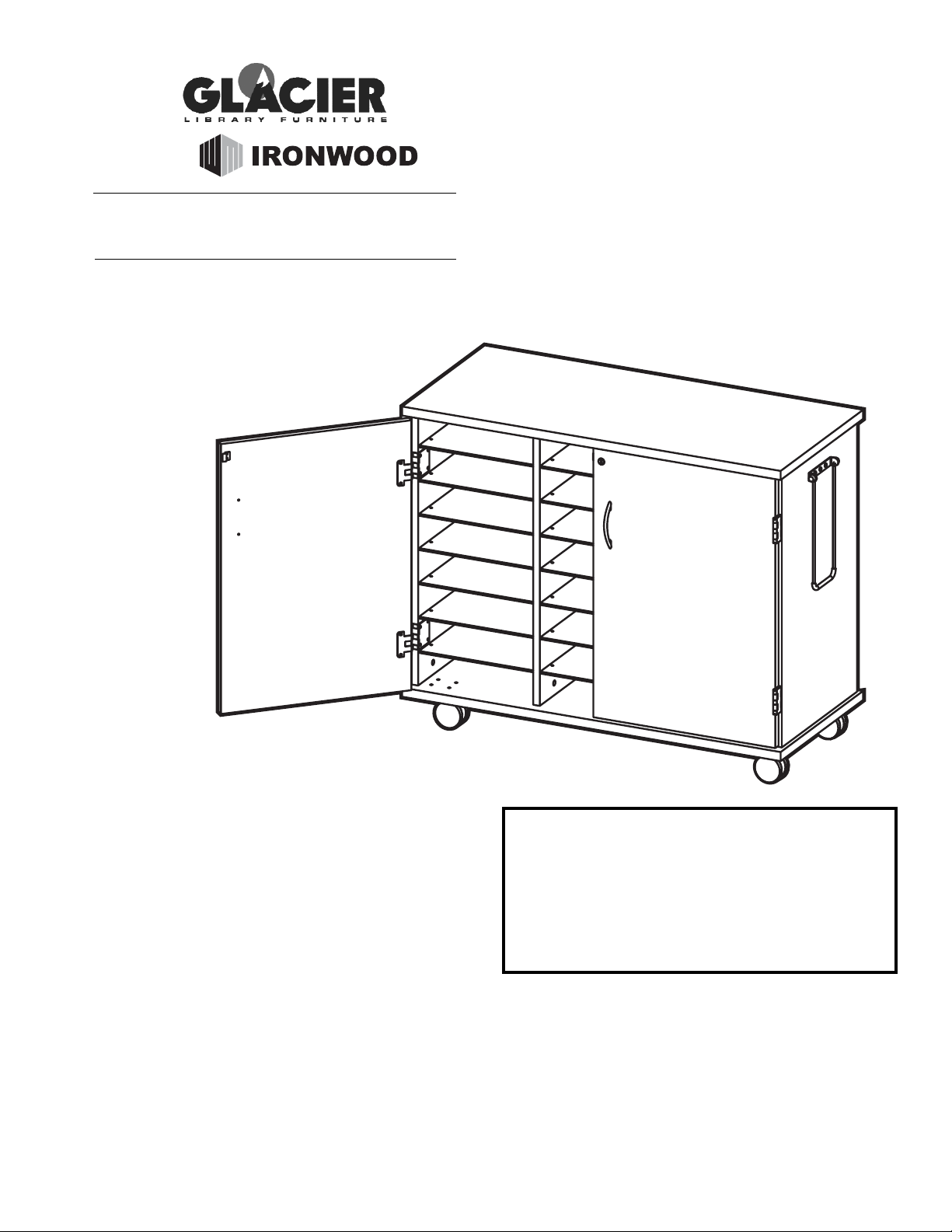
Ironwood GLACIER LSC User manual

LSC
LAPTOP STORAGE
CART
IMPORTANT!
Assembly may require the assistance of
another person.
Before you begin assembly:
READ THE DIRECTIONS all the way through one
time. This will speed up the process and help you
understand the sequence of steps.
COUNT THE PARTS AND HARDWARE before
assembly. This ensures you have received all
necessary parts before you begin.
TOOLS: You may need a Phillips head screwdriver,
a medium slotted screwdriver or a plastic mallet. To
protect your new furniture from damage during
assembly, it is recommended to work on a
carpeted surface.
CAUTION: On assemblies requiring glue, make
sure the unit is assembled correctly before gluing.
Once this unit is assembled with glue, the
manufacturer will not be responsible for damaged
parts. Keep a damp cloth or sponge handy to wipe
off excess glue.
To care for this furniture, simply wipe with a cloth
dampened with glass cleaner containing ammonia-D.
In the event any parts are missing from
this package, send your name, address,
telephone number, and a description of
the missing part(s) to: PARTS, Box 1420,
Missoula, MT 59806 or call:
1-800-769-5693 or FAX 1-800-445-5281.
BY
0808

L (1 ea) M (1 ea)
G (21 ea)
A B
C
J (2 ea)
E
D
PARTS DIAGRAM
Adjustable
Shelf 01050127 Divider 01050144
Left Door 01050173 Right Door 01050173
Top 01050101 1 ea.Right Side 01050141 1 ea.Left Side 01050141 1 ea.
Bottom 01050111 1 ea.
Back 01050152 1 ea.

H6 Swivel Caster 402640 4
H9 Barrel Nut 902200 3
H1 Minifix Cam 908810 28 H2 Wood Dowel 195000 20
H8 Nylok Nut 904420 16
H17 1" Washerhead
Screw 920200 4
H12 Door Bumper 298032 4
H20 Panel Clip H0981 84
H10 Pull Handle 490670 1
H3 Minifix Bolt 909834 28
H7 Long Machine
Screw 902201 16
H16 Door Pull 400870 2
H4 Hinge H0523 4
H11 Short Machine
Screw 901303 3
H5 #8 x5/8”
Flathead Screw H2040 32
H18
Lockset 250-HP 1 set
H15
Lock and
Key Set
1 ea.
#8-5/8” Panhead
4 ea.
H14
#6-3/4” Panhead
2 ea.
Catch Plate
1 ea.
H13
H19
Door Plate
1 ea.
HARDWARE

ASSEMBLED DISASSEMBLED
Using the Minifix System:
Insert the Minifix Cams into the
appropriate holes with the arrow
facing outwards as shown.
Using the #2 Phillips screwdriver,
rotate the Cam Devices a half turn
clockwise until snug.
To disassemble, turn the Cam
Devices counter-clockwise and
remove panels.
When screwing post into hole, Do
Not over tighten. Screw post down
until bottom face of post flange just
touches board surface.
Insert twelve Minifix Cams (H1)
into the Back (D) with the arrows
of the cams facing out.
#1
H1

Insert four Minifix Cams (H1) into
the Left Side (A) and the Right
Side (B) with the arrows of the
cams facing out.
#2
Insert two Dowels (H2) into each
Side (A & B) where indicated.
#3
Screw three Minifix Bolts
(H3) into each Side (A & B)
where indicated.
#4
Screw the Hinges (H4) to the
Left Side (A) using eight #8 x
5/8" Flathead Screws (H5) in the
pre-drilled holes.
#5
H4
H4
H2
H1
H3
H5 A

Screw the Hinges (H4) to
the Right Side (B) using
eight 8 x 5/8" Screws (H5)
in the pre-drilled holes.
#6
H4
H4
Attach the Back (D) to the Right
Side (B) making sure the position of
the top edges are located as shown.
Turn the Minifix Cams (H1)
clockwise to secure.
#7
H1
D
B
TOP
TOP
Attach the Back (D) to the
Left Side (A) making sure
the position of the top edges
are located as shown. Turn
the Minifix Cams (H1)
clockwise to secure.
#8
H1 D
B
A
Place the Bottom (E) face-
side-up as shown. Insert
eight Dowels (H2) where
indicated.
#9
H2
H5
B

Screw eleven Minifix Bolts
(H3) into the Bottom (E)
where indicated.
#10
Place the Bottom (E) with the front
edge as shown onto the assembly.
Turn the Minifix Cams (H1) of the
Left Side (A), Right Side (B), and
Back (D) clockwise to secure.
#11
A
BD
E
FRONT
FRONT
FRONT
H1
H1
H1
Attach to the underside of the Bottom (E) four Swivel Casters (H6). Use Long Machine
Screws (H7) passed through the panel and secured with Nylok Nuts (H8) as shown.
Tighten with the use of a Phillips screwdriver and a 7/16" wrench.
Stand the unit upright for further assembly.
#12
H7
H8
H6
E
TOP

Insert three Barrel Nuts (H9)
into the backside of Right Side
(B). Attach the Pull Handle
(H10) to the Right Side using
three Short Machine Screws
(H11) as shown.
#13
H11
H9
H10
Remove the backing from the
adhesive side of the Door
Bumpers (H12). Attach to the front
edge of the Dividers (J) in the
approximate locations shown.
#14
H12
H12
Insert four Minifix Cams
(H1) into each Divider (J)
with the arrows of the
cams facing out.
#15
H1
Position one of the Dividers (J) onto
the bolts and dowels of the Bottom
(E) as shown. Secure in place by
turning the cams (H1) clockwise.
#16
J
H1

Position the other Divider (J)
onto the bolts and dowels of the
Bottom (E) as shown with the
cams (H1) facing the first
Divider. Turn the cams clockwise
to secure in place.
#17
J
E
H1
Place the Top (C) underside-up as shown.
Insert eight Dowels (H2) where indicated.
Screw eleven Minifix Bolts (H3) into the
Top where indicated.
#18
Attach a Catch Plate (H13) to the
Top (C) as shown using two
#8x5/8" Panhead Screws (H15).
#19
Position the bolts and dowels of the
Top (C) into the cams of the Left
Side (A), Right Side (B), Back (D),
and Dividers (J) as shown. Turn the
cams (H1) clockwise to secure in
place.
#20
AJJ
B
D
H1
H1
H1
H1
H1 H1
H1
H2
H3
H15
H13

Attach a Door Pull (H16) to the
Left Door (L) and the Right
Door (M) using 1" Washerhead
Screws (H17).
#21
LM
H16 H16
Position the Lock (H18) onto the inner side of
the Right Door (M) oriented as shown. Secure
the Lock (H18) in place using two #6 x 3/4"
Panhead Screws (H14) into the pre-drilled
holes of the Right Door. Press the trim ring of
the lock over the keyhole portion of the lock on
the opposite side of the Right Door as shown.
#22
Attach a Door Plate (H19)
to the Left Door (L) using
two #8x5/8" Panhead
Screws (H15) as shown.
#23
Attach the Left Door (L) to the Left
Side (A) as shown using eight
#8 x 5/8" Flathead Screws (H5).
Attach the Right Door (M) to the
Right Side (B) as shown using eight
#8 x 5/8" Flathead Screws (H5).
#24
M
L
H16
H17
H15
H14 H19
H14

Insert Panel Clips
(H20) until completely
seated into the pre-
drilled holes of the
Sides (A & B) and the
Dividers (J) as shown.
#25
Place the Adjustable
Shelves (E) into the
posts of the Panel
Clips (H20) as
shown.
#26
E
#27
H20
Your Glacier Laptop Storage Cart
is now fully assembled and
ready for use.
Table of contents