Irritrol Climate Logic User manual

Get more doneTM
Introduction
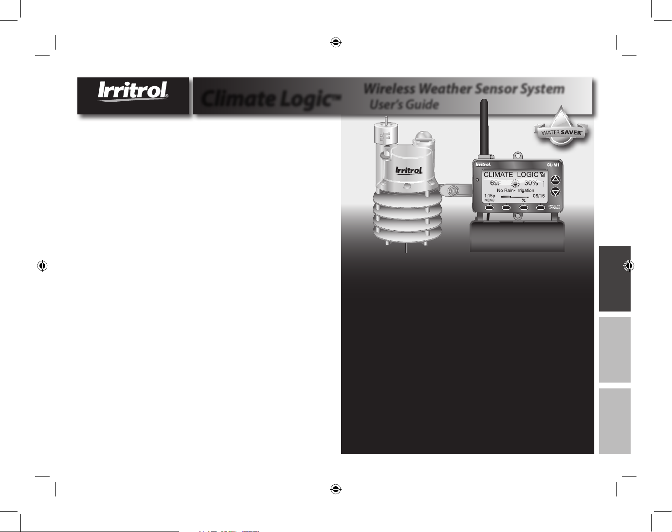
The Irritrol Climate LogicTM wireless weather sensor system
transforms your automatic irrigation control system into
a high-eciency, water resource-management center.
Compatible with remote-ready Irritrol and Toro controllers,
Climate Logic automatically regulates watering duration
corresponding to real-time weather conditions and specic
geographic and local weather prole information provided on
a region-specic Setup Card. In addition, integral rain and
freeze sensing further reduce wasteful, unnecessary irrigation
and icing conditions.
Your Climate Logic system consists of a self-contained,
Weather Sensor/Transmitter that continuously monitors
current air temperature, solar radiation and precipitation.
This data is transmitted at regular intervals throughout the
day to the Receiver Module; linked directly to your controller’s
remote control port. Each day, Climate Logic calculates and
adjusts the programmed station run time duration to the
amount required for the next automatic watering cycle.
The Climate Logic system is designed for easy installation,
setup and use. To take full advantage of the features and
capabilities provided by the Climate Logic system, take a
moment to review the detailed information provided within
this guide.
To answer any questions you may have regarding the Climate
Logic system, or any Irritrol product, please contact an Irritrol
Customer Service representative at (U.S.) 1-800-634-8873 or
(E.U.) +39 0765 40191.
Français Español English
L = 8" x W = 6", Grayscale, Printed on regular bond paper.
Climate LogicTM User’s Guide
Wireless Weather Sensor System
Quick Start Guide ................................................................... 2–3
System Components at a Glance ..................................... 4–5
CL-M1 Receiver Module .................................................. 4
CL-W1 Wireless Weather Sensor .................................. 5
Climate Logic System Installation ................................... 6–11
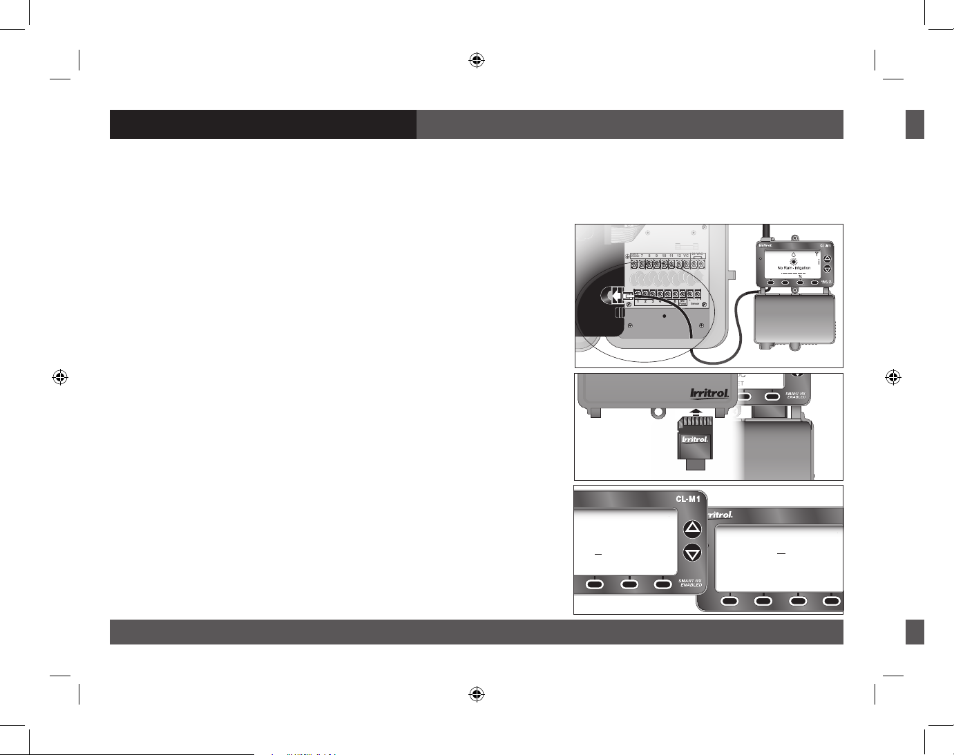
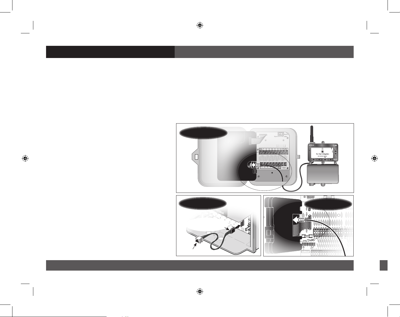
Receiver Module Installation and Setup.................. 6–8
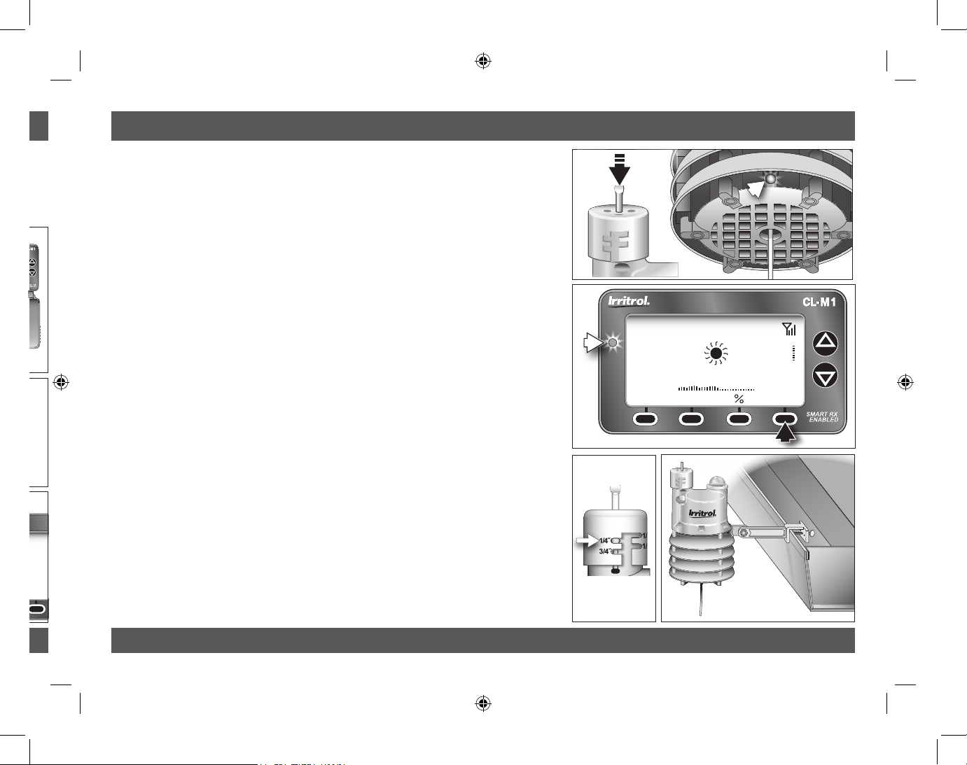
Weather Sensor Installation and Setup.................... 9–11
Climate Logic System Operation...................................... 12–19
Control Feature Setup Options.................................... 12
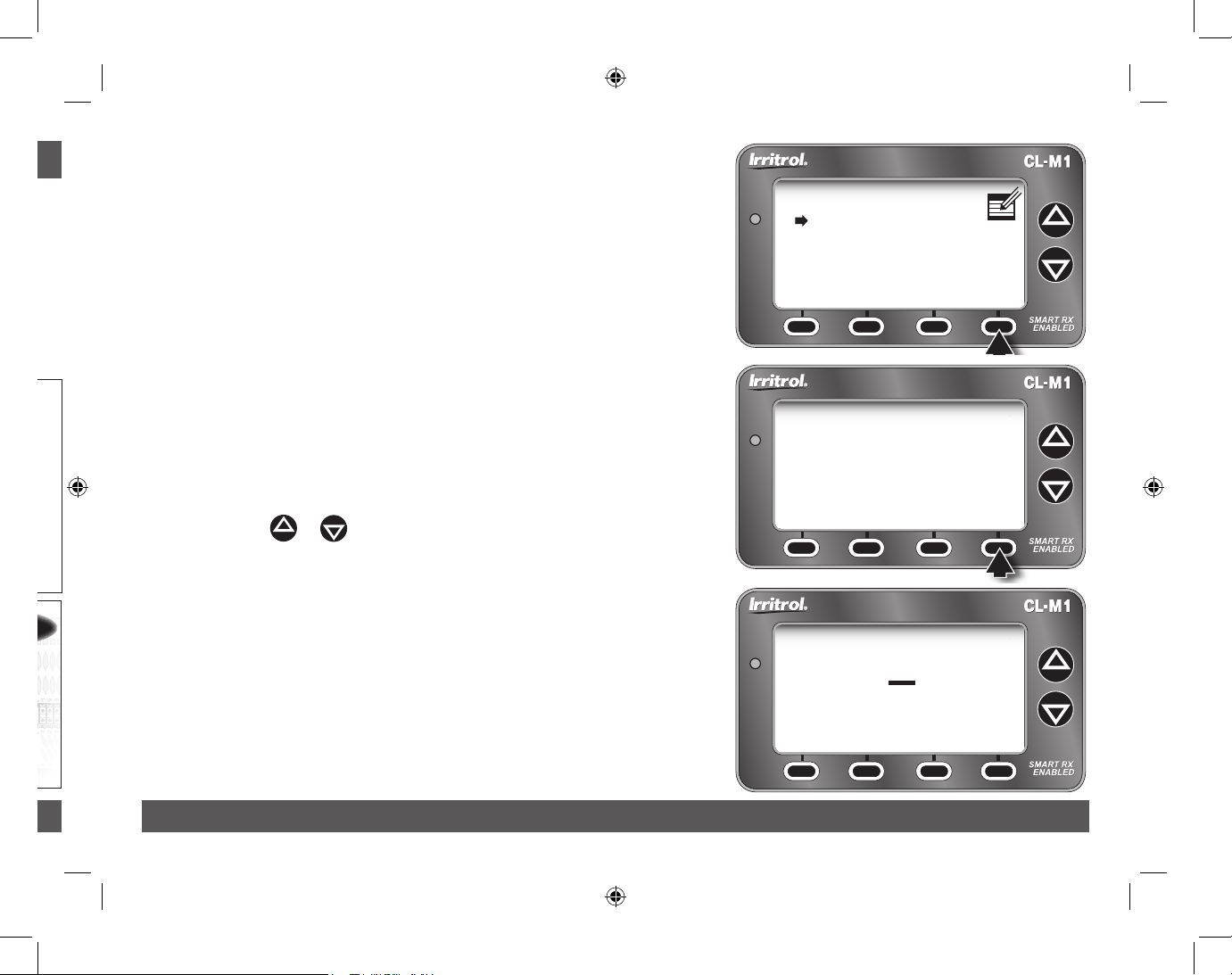
Setup Menu Options ........................................................ 13
Utility Menu Options........................................................ 14
Water Adjust Feature........................................................ 15
Rain/Freeze Sensor Control Feature.......................... 16
Water History Review Feature...................................... 17
Weather Sensor Identication Feature..................... 18
Control System Synchronization................................. 19
Remote PIN Setup.............................................................. 19
Weather Sensor Battery Replacement........................... 20
Specications ........................................................................... 21
FCC Information ...................................................................... 22

2Topic
Climate Logic System Quick-Start Guide
The Quick-Start guide provides the essential steps required to properly install and setup the
Climate Logic system in the most direct route possible. As needed, refer to the detailed information
on the page number listed with each step.
Step 1 –Connect and secure the Receiver Module next
to the controller. See page 6.
Step 2 – Adjust controller program A for the hottest/
driest conditions expected, without causing
over-watering and runo. Retain all watering
time/day restrictions in the program schedule
as required See page 6.
Step 3 – Synchronize the Receiver Module and controller
to the current time and date. See page 7.
Step 4 – Insert the Receiver Module Setup Card as
shown. See page 8.
Step 5 – Establish your location by entering the ve-digit
ZIP code, or Lat/Lon coordinates as preferred.
See page 8.
2Quick Start Setup Guide
Quick Start Setup Guide 3
Quick-Start Guide
S
tep 6 – Press and hold the sensor Test Pin for 10–15
seconds to activate the Weather Sensor!
A red LED (viewable through the lower vent
ring) will illuminate twice after 10 seconds to
conrm activation (if not already active).
See page 9.
Step 7 – Press the sensor Test Pin again to conrm
signal reception at the Receiver Module. The
receiver’s red LED will turn on momentarily
when the signal is received. Press the BYPASS
key to cancel the Dry-out mode delay period
and resume normal operation. See page 9.
Note: If the LED does not turn on, refer to the
Weather Sensor setup procedure on page 19.
Step 8 – Check the Rain Sensor threshold setting and
adjust as needed. See page 10.
S
tep 9 – Secure the Weather Sensor to a rain gutter
or other suitable structure that provides
unrestricted exposure. Adjust the sensor
alignment to vertical. See page 11.
EARTH
GROUND
MV/
Pump Sensor
+-
7 8 9 10 11 12
1 2 3 4 5 6
24 VAC
VC
MENU
_ _ _ F100%
CLIMATE LOGIC
9:15a11/16
THIS SIDE UP
THIS SIDE UP
CLIMATE LOGIC
MENU
1:15
a
11/16
69F30%
CLIMATE LOGIC
SETUP CARD
CLIMATE LOGIC
SETUP CARD
TM
CLIMATE LOGIC
MENU SET LOC
No Rain - Irrigation
MUST SET LOCATION
F40%
– – –
CLIMATE LOGIC
SETUP CARD
CLIMATE LOGIC
SETUP CARD
THIS SIDE UP
CLIMATE LOGIC
CLIMATE LOGIC
CLIMATE LOGIC
TM
TM
Location
LAT
LONG
North America
-000.0000
00.0000
SAVE CANCEL ZIP NEXT
Location
ZIP
00000
SAVE
CANCEL LAT NEXT

2Topic
Climate Logic System Quick-Start Guide
The Quick-Start guide provides the essential steps required to properly install and setup the
Climate Logic system in the most direct route possible. As needed, refer to the detailed information
on the page number listed with each step.
Step 1 –Connect and secure the Receiver Module next
to the controller. See page 6.
Step 2 – Adjust controller program A for the hottest/
driest conditions expected, without causing
over-watering and runo. Retain all watering
time/day restrictions in the program schedule
as required See page 6.
Step 3 – Synchronize the Receiver Module and controller
to the current time and date. See page 7.
Step 4 – Insert the Receiver Module Setup Card as
shown. See page 8.
Step 5 – Establish your location by entering the ve-digit
ZIP code, or Lat/Lon coordinates as preferred.
See page 8.
2Quick Start Setup Guide
Quick Start Setup Guide 3
Quick-Start Guide
Step 6 – Press and hold the sensor Test Pin for 10–15
seconds to activate the Weather Sensor!
A red LED (viewable through the lower vent
ring) will illuminate twice after 10 seconds to
conrm activation (if not already active).
See page 9.
Step 7 – Press the sensor Test Pin again to conrm
signal reception at the Receiver Module. The
receiver’s red LED will turn on momentarily
when the signal is received. Press the BYPASS
key to cancel the Dry-out mode delay period
and resume normal operation. See page 9.
Note: If the LED does not turn on, refer to the
Weather Sensor setup procedure on page 19.
Step 8 – Check the Rain Sensor threshold setting and
adjust as needed. See page 10.
Step 9 – Secure the Weather Sensor to a rain gutter
or other suitable structure that provides
unrestricted exposure. Adjust the sensor
alignment to vertical. See page 11.
EARTH
GROUND
MV/
Pump Sensor
+-
7 8 9 10 11 12
1 2 3 4 5 6
24 VAC
VC
MENU
_ _ _ F100%
CLIMATE LOGIC
9:15a11/16
Location
LAT
LONG
North America
-000.0000
00.0000
SAVE CANCEL ZIP NEXT
CLIMATE LOGIC
52F40%
Dry Out Remain 12h
MENU
10:15a
BYPASS
11/16

4Climate Logic at a Glance
Climate Logic at a Glance 5
System Components at a Glance
1– Antenna
2 – LCD Screen: Large-format LCD screen
provides enhanced clarity and use of
text and graphics.
3 – Up/Down Arrow Keys: Control Menu
cursor position, and adjust denable
screen values.
4 – Setup Card: Provides historical weather
data for regional location specied by
ZIP code or Lat/Lon coordinates.
5 – CMR-ADP KwikDial Adaptor Cable:
Adapts RJ25 connector to KwikDial
controller’s 5-pin receptacle.
6 – Cover: Provides weather-resistance and
display protection in closed position.
7 – Connector Cable: Plugs into controller’s
remote control receptacle.
8 – Multifunction Keys: Key function is
congured for each screen as required.
9 – LED Status Indicator: Remains On
when irrigation is suspended; ashes
when bypassed.
CLIMATE LOGIC
MENU
1:15a11/16
69F40%
CLIMATE LOGIC
SETUP CARD
CLIMATE LOGIC
SETUP CARD
THIS SIDE UP
THIS SIDE UP
TM
1
3
4
9
8
7
2
65
CL-M1 Receiver Module
CL-W1 Wireless Weather Sensor

4Climate Logic at a Glance
Climate Logic at a Glance 5
1 – Weather Sensor Test Pin
Pressed to simulate rain sensor
operation and test communication.
2 – Rain Sensor Adjustment Cap
Adjusts Rain Sensor threshold to a
nominal setting of 1/8”, 1/4”, 1/2” or 3/4”
(3 mm, 6 mm, 12 mm or 19 mm)
of accumulated rainfall.
3 – Solar Collector
Collects and measures solar radiation.
Requires full exposure to sunlight.
4 – Battery Compartment
Factory-installed 9V-Alkaline battery
can sustain normal Weather Sensor
operations up to ve years.
5 – QuickClipTM Mounting Bracket
Convenient QuickClip mounting
bracket provides quick and easy
Weather Sensor installation.
6 – Temperature Sensor (not shown)
7 – RF Transmission LED (not shown)
8 – Antenna Wire
CLIMATE LOGIC
MENU
1:15a11/16
69F40%
CLIMATE LOGIC
SETUP CARD
CLIMATE LOGIC
SETUP CARD
THIS SIDE UP
THIS SIDE UP
TM
4
123
4
5
8
CL-M1 Receiver Module
CL-W1 Wireless Weather Sensor
6
7

6Receiver Module Installation and Setup
Receiver Module Installation and Setup 7
4. The Receiver Module will automatically* synchronize time
and date with the host controller upon initial power-up.
* Note: Does not apply to TMC-212 controller.
5. Verify that the time and date are synchronized correctly.
If necessary, adjust the Receiver Module as follows:
Note: The display will automatically return to the Home screen
if a key is not pressed within 60 seconds.
• PresstheMENU key to display the Main Menu screen.
(The CLOCK menu option is selected by default.)
• PresstheENTER key to display the Clock review screen.
• PresstheSETUP key to display the Set Clock screen.
Note: To download the current time and date from the control-
ler, press the GET key. When prompted, press the YES key. .
• Pressthe or key to adjust the selected (underscored)
value. Press the NEXT key to select the next value. Continue
setting the current day, year and time.
Note: To change the clock time display format, press the 12/24
key. To return to the previous screen without making changes,
press the CANCEL key.
• WhentheReceiverModuleandcontrolleraresynchronized
to the current time and date, press the SAVE key.
• PresstheEXIT key two times to return to the Home screen.
Climate Logic System Installation Receiver Module Installation and Setup
Note: Installation methods must comply with all applicable national and local building codes.
1. Setup controller watering Program A to provide an irrigation baseline for the Climate Logic system.
The station run time, cycle start time(s), and watering day schedule*must be congured for the
hottest/driest conditions expected, without causing over-watering and runo. Retain all watering
time/day restrictions in the program schedule as required.
Note: By default, Climate Logic modies the run time of stations assigned only to Program A. To include
Program B, or Programs Band C, see page 13.
*Note: For TMC-212 controller only: Inter-
val day scheduling is not compatible with
Climate Logic. Calendar and Odd/Even
schedules are not aected.
2. Route the connection cable into the con-
troller cabinet. Insert the cable connector
into the controller’s remote control jack.
Note: Use the provided CMR-ADP cable
adapter assembly for KwikDial and MC-E
(Blue) controller applications.
3. Secure the Receiver Module to the wall
next to the controller using the provided
screws or other suitable fasteners.
Note: For indoor application, adhesive-
backed hook and loop tape (not included)
can be used instead of screws.
EARTH
GROUND
MV/
Pump Sensor
+-
7 8 9 10 11 12
1 2 3 4 5 6
24 VAC
VC
MENU
_ _ _ F100%
CLIMATE LOGIC
9:15a11/16
MV/
PUMP
1 2 3 4 5 6 7 8 9 10 11 12
MV/
PUMP
24VAC
RAIN
SENSOR
REMOTE
GND
1 2 3 4 5 6 7 8 9 10 11 12
VC/
COM
VC/
COM
13 14 15 16 17 18 19
VC/
COM
37 38 39 40 41 42 43
37 38 39 40 41 42 43
25 26 27 28 29 30 31 32 33 34 35 36
25 26 27 28 29 30 31 32 33 34 35 36
VC/
COM
VC/
COM
VC/
COM
VC/
COM
13 14 15 16 17 18 19
VC/
COM
MV/
PUMP
1 2 3 4 5 6 7 8 9 10 11 12
MV/
PUMP
24VAC
RAIN
SENSOR
REMOTE
GND
1 2 3 4 5 6 7 8 9 10 11 12
VC/
COM
VC/
COM
13 14 15 16 17 18 19
VC/
COM
37 38 39 40 41 42 43
37 38 39 40 41 42 43
25 26 27 28 29 30 31 32 33 34 35 36
25 26 27 28 29 30 31 32 33 34 35 36
VC/
COM
VC/
COM
VC/
COM
VC/
COM
13 14 15 16 17 18 19
VC/
COM
POSTHOT
Total Control-R
CMR-ADP
Blue Wire
(Up) to Pin 1
Rain Dial-R
KwikDial

6Receiver Module Installation and Setup
Receiver Module Installation and Setup 7
4. The Receiver Module will automatically* synchronize time
and date with the host controller upon initial power-up.
* Note: Does not apply to TMC-212 controller.
5. Verify that the time and date are synchronized correctly.
If necessary, adjust the Receiver Module as follows:
Note: The display will automatically return to the Home screen
if a key is not pressed within 60 seconds.
• PresstheMENU key to display the Main Menu screen.
(The CLOCK menu option is selected by default.)
• PresstheENTER key to display the Clock review screen.
• PresstheSETUP key to display the Set Clock screen.
Note: To download the current time and date from the control-
ler, press the GET key. When prompted, press the YES key. .
• Pressthe or key to adjust the selected (underscored)
value. Press the NEXT key to select the next value. Continue
setting the current day, year and time.
Note: To change the clock time display format, press the 12/24
key. To return to the previous screen without making changes,
press the CANCEL key.
• WhentheReceiverModuleandcontrolleraresynchronized
to the current time and date, press the SAVE key.
• PresstheEXIT key two times to return to the Home screen.
Climate Logic System Installation Receiver Module Installation and Setup
Note: Installation methods must comply with all applicable national and local building codes.
1. Setup controller watering Program A to provide an irrigation baseline for the Climate Logic system.
The station run time, cycle start time(s), and watering day schedule*must be congured for the
hottest/driest conditions expected, without causing over-watering and runo. Retain all watering
time/day restrictions in the program schedule as required.
Note: By default, Climate Logic modies the run time of stations assigned only to Program A. To include
Program B, or Programs Band C, see page 13.
*Note: For TMC-212 controller only: Inter-
val day scheduling is not compatible with
Climate Logic. Calendar and Odd/Even
schedules are not aected.
2. Route the connection cable into the con-
troller cabinet. Insert the cable connector
into the controller’s remote control jack.
Note: Use the provided CMR-ADP cable
adapter assembly for KwikDial and MC-E
(Blue) controller applications.
3. Secure the Receiver Module to the wall
next to the controller using the provided
screws or other suitable fasteners.
Note: For indoor application, adhesive-
backed hook and loop tape (not included)
can be used instead of screws.
Main Menu
Clock
Location
Setup
Timer
Remote
Utility
Sensor
EXIT ENTER
Clock
03/15/2011 02:06P
EXIT SETUP GET
Set Clock
03/15/2011
02:06P
SAVE
MONTH
CANCEL 12/24 NEXT
MV/
PUMP
1 2 3 4 5 6 7 8 9 10 11 12
MV/
PUMP
24VAC
RAIN
SENSOR
REMOTE
GND
1 2 3 4 5 6 7 8 9 10 11 12
VC/
COM
VC/
COM
13 14 15 16 17 18 19
VC/
COM
37 38 39 40 41 42 43
37 38 39 40 41 42 43
25 26 27 28 29 30 31 32 33 34 35 36
25 26 27 28 29 30 31 32 33 34 35 36
VC/
COM
VC/
COM
VC/
COM
VC/
COM
13 14 15 16 17 18 19
VC/
COM
MV/
PUMP
1 2 3 4 5 6 7 8 9 10 11 12
MV/
PUMP
24VAC
RAIN
SENSOR
REMOTE
GND
1 2 3 4 5 6 7 8 9 10 11 12
VC/
COM
VC/
COM
13 14 15 16 17 18 19
VC/
COM
37 38 39 40 41 42 43
37 38 39 40 41 42 43
25 26 27 28 29 30 31 32 33 34 35 36
25 26 27 28 29 30 31 32 33 34 35 36
VC/
COM
VC/
COM
VC/
COM
VC/
COM
13 14 15 16 17 18 19
VC/
COM
POSTHOT
Total Control-R

8Receiver Module Installation
Weather Sensor Installation and Setup 9
Weather Sensor Installation and Setup
Important: The Climate Logic Weather Sensor is shipped with
the battery circuit deactivated. To initially activate the sensor prior
to installation, press and hold the Test Pin for 10–15 seconds. A red
LED, viewable from the lower vent area, will illuminate twice after
10 seconds (if not already active).
Note: The Weather Sensor and Receiver Module are paired for wireless
communication from the factory. The following procedure will only be
required if Please Add Sensor is displayed on the Home screen.
1. Pair the Weather Sensor transmitter with the Receiver Module
to establish wireless communications as follows:
• FromtheHome screen, press the ADDSEN key to display
the Sensor Setup screen. Press the ADD key to initiate the
sensor ID search function.
• PressandreleasetheTest Pin to “Ping” the Receiver Module.
When pairing is successful, the 7-digit sensor ID is displayed.
6. With the cover closed,
insert the Climate Logic
Setup Card into the
Receiver Module slot as
shown. Open the cover
to proceed.
Note: The Home screen
(right) will be displayed
only when a location has not been established, or has been
erased. Press the SET LOC key to display the Location screen.
7. Establish the site location as follows:
• PressMENU _LOCATION _ENTER to display the Location
screen.
Note: The Lat/Lon Location screen will be displayed by default.
To set the location using a 5-digit ZIP code, press the ZIP key.
• Pressthe or key to adjust the selected value. Press the
NEXT key to select the next value in sequence.
• Whenthelocationinformationisdisplayedcorrectly,press
the SAVE key.
Note: The Receiver Module will begin transferring specic data
from Setup Card for the dened location. A conrmation screen
will indicate the completed transfer.
• PresstheEXIT key (two times) to return to the Home screen.
8. Remove the Setup Card and stow inside the controller cabinet.
THIS SIDE UP
THIS SIDE UP
CLIMATE LOGIC
MENU
1:15a11/16
69F30%
CLIMATE LOGIC
SETUP CARD
CLIMATE LOGIC
SETUP CARD
TM
CLIMATE LOGIC
MENU SET LOC
No Rain - Irrigation
MUST SET LOCATION
F40%
– – –
CLIMATE LOGIC
SETUP CARD
CLIMATE LOGIC
SETUP CARD
THIS SIDE UP
CLIMATE LOGIC
CLIMATE LOGIC
CLIMATE LOGIC
TM
TM
CLIMATE LOGIC
MENU SET LOC
No Rain - Irrigation
MUST SET LOCATION
F40%
– – –
Location
ZIP
00000
SAVE CANCEL LAT NEXT
Location
LAT
LONG
North America
-000.0000
00.0000
SAVE CANCEL ZIP NEXT

8Receiver Module Installation
Weather Sensor Installation and Setup 9
Weather Sensor Installation and Setup
Important: The Climate Logic Weather Sensor is shipped with
the battery circuit deactivated. To initially activate the sensor prior
to installation, press and hold the Test Pin for 10–15 seconds. A red
LED, viewable from the lower vent area, will illuminate twice after
10 seconds (if not already active).
Note: The Weather Sensor and Receiver Module are paired for wireless
communication from the factory. The following procedure will only be
required if Please Add Sensor is displayed on the Home screen.
1. Pair the Weather Sensor transmitter with the Receiver Module
to establish wireless communications as follows:
• FromtheHome screen, press the ADDSEN key to display
the Sensor Setup screen. Press the ADD key to initiate the
sensor ID search function.
• PressandreleasetheTest Pin to “Ping” the Receiver Module.
When pairing is successful, the 7-digit sensor ID is displayed.
CLIMATE LOGIC
MENU SET LOC
No Rain - Irrigation
MUST SET LOCATION
F40%
– – –
Location
ZIP
00000
SAVE CANCEL LAT NEXT
Location
LAT
LONG
North America
-000.0000
00.0000
SAVE CANCEL ZIP NEXT
Sensor Setup
Add Sensor
Searching.......
EXIT ADD
Sensor Setup
ET Sensor ID: 0065157
Successful
Sensor Found
EXIT
MENU ADD-SEN
PLEASE ADD SENSOR
_ _ _ F100%
CLIMATE LOGIC

10 Weather Sensor Installation
Weather Sensor Installation 11
3. The Climate Logic system is designed to provide
eective wireless communication in most applications.
Loss of range can result from interference in the signal
path. To verify signal reception from the selected
installation site, perform the following test:
•Startamanualwateringoperationofazonethatcan
be seen from the installation site. Press and hold the
Sensor Test Pin. If the signal is received, watering
should shut o within a short time.
•NotethesignalbarsontheHomescreentoverify
good signal strength. Three bars is optimal.
•PresstheBYPASS key to cancel the Dry-out delay
mode to resume normal operation.
4. Install the Weather Sensor using either of the following
methods:
•Forraingutterinstallation,unscrewthebracket
thumbscrew enough to clear the rain gutter edge.
HoldingtheWeatherSensorinposition,tightenthe
thumbscrew securely.
•Forwoodstructureinstallation,removethe
thumbscrew and secure the bracket using the
provided screws or appropriate stainless fasteners.
•Adjusttheverticalalignmentasneededbyloosening
the phillips screw at the bracket joint; adjust to vertical,
then tighten securely.
• PresstheEXIT key (three times) to return to the Home screen.
After a brief time, the current temperature, watering history
graph line, and signal-strength bars will be displayed.
Note: A single Weather Sensor can be paired to multiple Receiver
Modules when additional Climate Logic systems are installed
within reception range.
2. The Rain Sensor default threshold is ¼” (6 mm) of accumulated
rainfall (nominal). The threshold can be lowered to ⁄” (3 mm) or
raised to ½” (12 mm), or ¾” (19 mm) as preferred. Prior to install-
ing the Weather Sensor, adjust the threshold to the preferred setting as follows:
Note: Increasing the threshold extends the length of time required for the Weather Sensor to signal the
Receiver Module to stop irrigation, as well as extending the dry-out period before scheduled watering can
resume. In areas where heavy fog, mist or high humidity is common, the ⁄” (3 mm) setting is not recom-
mended due to the increased sensitivity to moisture.
•TurntheRainSensorcapslightly,releasingitfromthe
retention pins, allowing the cap to move vertically.
•Turn the cap to engage the retention pins at the preferred
slot position.
Important: The Weather Sensor must have full exposure to sun, wind and rain, and must not be installed
inside a rain gutter, or in any location where immersion, runo, or contact with irrigation spray will occur.
Avoid installation near a heat source, such as a heater vent or chimney. Wooden surfaces are preferred
to concrete or asphalt shingles to reduce reected heat. Installation over a planted area is preferred to a
driveway, walkway etc. Avoid installation near any large metal structure, or high current-draw equipment
that can cause signal interference. Ensure the antenna wire hangs vertically without contact.
CLIMATE LOGIC
MENU
2:32p11/16
69F40%

12 Control Feature Setup Options
Setup Menu Options 13
Setup Menu Options
The following Setup features are accessed through the ET Setup
menu (MENU _SETUP _ENTER).
All setup parameters are selected, adjusted and entered using the
NEXT/BACK, / and SAVE keys.
Auto Program Adjust: In all cases, Climate Logic regulates the
run time of all stations assigned to Program A. The Auto Program
Adjust feature enables stations assigned to Program B, or Programs
B and C to be regulated as well.
Watering Restriction Setup: This feature enables the Climate
Logic system to restrict watering for a specied daily time period.
The restriction-period start time can be set to any hour of the day.
The duration period can be set from 0 to 24 hours, in 30-minute
increments.
Schedule Update Time: The Weather Sensor transmits weather-
related data to the Receiver Module at regular intervals throughout
the day. At the default time of 8:00 p.m., the watering adjustment
factor for the next 24 hours is calculated and updated on the Home screen. The Schedule Update Time can
be set to any hour of the day, but is recommended to occur between scheduled watering operations.
Average Percent Days: This setting denes how many days of compiled weather data are used to calculate
the current watering adjustment % factor. By default, Climate Logic compiles data from the three previous
days to provide a moderately smooth adjustment factor. This feature can be adjusted from 1 to 7 days.
Decreasing the number of days, increases the adjustment variation; increasing the number of days results
in less variation and a smoother daily average.
Climate Logic System Operation Control Feature Setup Options
The Climate Logic system control features, accessible through the Setup and Utility menu screens,
determine how and when the system displays information and performs various functions that regulate
weather-dened automatic irrigation. The control feature-set, listed below in menu order, includes the
factory default setting and the setup parameter for each.
Setup Menu Features Default Setup Parameter
Auto Program Adjust Program A Program A, A &B or A, B &C
Water Restriction Start Time None Any hour
Water Restriction Duration None 0–24 hours (in ½-hour increments)
Schedule Update Time 8:00 p.m. Any hour
Average Percent Days 3 1–7 Days
Freeze Temperature 39° F (4° C) 35°–45° F (2°–7° C) (in 2° increments)
Dry-out days 0.5 0–3 days (in ½-day increments)
Utility Menu Features Default Setup Parmater
Contrast Balanced Increase/Decrese (incremental)
Units
(of measure/time format)
English,
12H
Metric,
24H
Note: History, Default, Loader, and About utility menu items are provided for reference and service use only, and
do not provide user-dened setup options. Refer to page 17 for detailed History feature information.
ET Setup
Auto Program Adjust A
Water Restrict NONE
Water Restrict Time(hr) 0.0
SAVE
1 of 3
BACKCANCEL NEXT
ET Setup
Schedule Update 08:00 P.M.
Average Percent Days 3
SAVE
2 of 3
BACKCANCEL NEXT

Utility Menu Options / Water Adjust Feature 15
14 Setup / Utility Menu Options
Default (DEFAULT _ENTER): The Default utility feature enables
all user-dened setup parameters to be either erased and reset to
the factory default settings, or a complete system reset includ-
ing Location, History, and Sensor Pairing.*
•PresstheYES key to reset to the Factory Default settings.
See Default settings listed on page 12.
•PresstheNO key to return to the previous screen.
•Pressthe ERASE key to display the Erase All prompt screen.
• PresstheNO key to return to the Utility Menu screen.
•PresstheFACTORY key to return the Factory Reset screen.
•
*Press the YES key to initiate the complete system reset.
Complete the procedure as indicated on the prompt screens.
Water Adjust Feature
The Water Adjust feature enables watering time to be ne-tuned
by applying small adjustments universally to all weather-regulated
stations.
F
rom the Home screen, press the or key to access the
Water Adjust screen and to adjust scale. Press the SAVE key
to enter the change and return to the Home screen.
Note: If a particular watering zone appears over-or under-watered,
adjust the station run time in the controller watering program.
It is considered best practice to make adjustments in small increments;
allowing several days between changes to observe the results.
Freeze Temperature (threshold): The freeze sensor activation
threshold can be adjusted from 39° F (4° C), (default) down to 35° F
(2° C), or increased to 45° F (7° C), in 2° increments.
Important: Freeze sensor operation should be used only when the
watered area can be visually monitored. While the Freeze Sensor is
designed to cancel watering when air temperature is near freezing,
automatic watering can occur in certain circumstances. For example,
the air temperature may rise slightly above the sensor threshold, while
the temperature of the adjacent walkways remains below freezing.
Watering in this condition can result in unsafe walkway conditions. The Freeze Sensor feature is not intended to
replace any winterization procedures normally used to prevent freeze-related irrigation system damage.
Dry-out Days: This setting determines the minimum length of time that must elapse after the release of
a rain/freeze hold, and automatic watering can resume. By default, the dry-out period is ½ day (12 hours),
and is adjustable from 0 to 3 days in ½-day increments.
Utility Menu Options
The following Utility features are accessed through the Utility
Menu screen (MENU _UTILITY _ENTER).
Display Contrast (CONTRAST _ENTER): The LCD screen contrast
is factory set at the midpoint adjustment range. Contrast intensity
can be adjusted incrementally to the preferred level.
Units: (UNITS _ENTER): By default, all units of measure are dis-
played in English standard format, and time in 12-hour (a.m./p.m.)
format. Metric units of measure, and/or 24-hour (military time)
formats can be selected as preferred.
ET Setup
Freeze Temperature 39F
Dry Out (days) 0.0
SAVE
3 of 3
BACKCANCEL NEXT
Utility Menu
Contrast
Units
History
Loader
About
Default
EXIT ENTER

Utility Menu Options / Water Adjust Feature 15
14 Setup / Utility Menu Options
Default (DEFAULT _ENTER): The Default utility feature enables
all user-dened setup parameters to be either erased and reset to
the factory default settings, or a complete system reset includ-
ing Location, History, and Sensor Pairing.*
•PresstheYES key to reset to the Factory Default settings.
See Default settings listed on page 12.
•PresstheNO key to return to the previous screen.
•Pressthe ERASE key to display the Erase All prompt screen.
• PresstheNO key to return to the Utility Menu screen.
•PresstheFACTORY key to return the Factory Reset screen.
•*Press the YES key to initiate the complete system reset.
Complete the procedure as indicated on the prompt screens.
Water Adjust Feature
The Water Adjust feature enables watering time to be ne-tuned
by applying small adjustments universally to all weather-regulated
stations.
From the Home screen, press the or key to access the
Water Adjust screen and to adjust scale. Press the SAVE key
to enter the change and return to the Home screen.
Note: If a particular watering zone appears over-or under-watered,
adjust the station run time in the controller watering program.
It is considered best practice to make adjustments in small increments;
allowing several days between changes to observe the results.
Freeze Temperature (threshold): The freeze sensor activation
threshold can be adjusted from 39° F (4° C), (default) down to 35° F
(2° C), or increased to 45° F (7° C), in 2° increments.
Important: Freeze sensor operation should be used only when the
watered area can be visually monitored. While the Freeze Sensor is
designed to cancel watering when air temperature is near freezing,
automatic watering can occur in certain circumstances. For example,
the air temperature may rise slightly above the sensor threshold, while
the temperature of the adjacent walkways remains below freezing.
Watering in this condition can result in unsafe walkway conditions. The Freeze Sensor feature is not intended to
replace any winterization procedures normally used to prevent freeze-related irrigation system damage.
Dry-out Days: This setting determines the minimum length of time that must elapse after the release of
a rain/freeze hold, and automatic watering can resume. By default, the dry-out period is ½ day (12 hours),
and is adjustable from 0 to 3 days in ½-day increments.
Utility Menu Options
The following Utility features are accessed through the Utility
Menu screen (MENU _UTILITY _ENTER).
Display Contrast (CONTRAST _ENTER): The LCD screen contrast
is factory set at the midpoint adjustment range. Contrast intensity
can be adjusted incrementally to the preferred level.
Units: (UNITS _ENTER): By default, all units of measure are dis-
played in English standard format, and time in 12-hour (a.m./p.m.)
format. Metric units of measure, and/or 24-hour (military time)
formats can be selected as preferred.
ET Setup
Freeze Temperature 39F
Dry Out (days) 0.0
SAVE
3 of 3
BACKCANCEL NEXT
Utility Menu
Contrast
Units
History
Loader
About
Default
EXIT ENTER
Reset To
Factory Defaults?
YES NOERASE
WATER ADJUST
MORELESS
SAVE CANCEL
Erase All?
All data will be lost!
YES NOFACTORY

Water History Review Feature 17
Water History Review Feature
The Climate Logic system tracks and records the daily adjust-
ment factor for a rolling, two-year period. A one-month snap-
shot is represented by the small bar graph on the Home screen.
The graph is updated daily, and builds from the left to right,
with the most recent day appearing on the left of the scale.
Pressing the %key displays the Water History graph in a
large-scale format. By default, the graph represents the daily
adjustment history for a one-month period. Pressing the ZOOM
key displays the history data in time frames of approximately
2-months, 6-months, 1-year, and 2-years.
Watering history data can also be reviewed in a contextual
format, accessible through the History option of the Utility
Menu. MENU _UTILITY _HISTORY.
The History screen lists the date and adjustment % value for
each day in chronological order, with the most recent entry at
the bottom. Use the NEXT and BACK keys to scroll through the
data screens.
Note: Data displayed in the LOGFILE screen is provided for service
use only.
16 Rain/Freeze Sensor Control Feature
Rain/Freeze Sensor Control Feature
When rain or a low temperature condition is detected, system
operation is placed on hold. The Sun icon is replaced with the
corresponding Rain Cloud or Snow Flakes icon. The LED status
indicator is on continuously while the system is on Hold.
When weather conditions improve, the Climate Logic system
automatically resets for normal operation. An adjustable
Dry-out period will prevent automatic watering for 12 hours (by
default) before scheduled watering can resume. The Dry-out
mode is adjustable from 0 to 3 days, in ½-day increments.
To adjust the Dry-out time period, refer to the Dry-out Days
setup procedure on page 14.
Note: To resume watering operation immediately after the reset,
press the BYPASS key to skip the Dry-out mode.
Smart Bypass Mode: While the system is on hold, sensor control
can be toggled Off and On by pressing the BYPASS key. The
Bypass mode will be indicated on the Home screen, and the
LED indicator will blink continuously. Watering operations can
resume, however the Climate Logic system will remain in the
Bypass mode until the system automatically resets after the
Dry-out duration times out.
Note: To resume sensor control mode, press the BYPASS key again
to toggle the Bypass mode O.
CLIMATE LOGIC
MENU
10:15a
Rain Sensor - Bypassed
52F40%
BYPASS
11/16
CLIMATE LOGIC
52F40%
Dry Out Remain 12h
MENU
10:15a
BYPASS
11/16
CLIMATE LOGIC
MENU
BYPASS
10:15
a
Rain - No Irrigation
11/16
52F40%
CLIMATE LOGIC
MENU
BYPASS
3:15a
Cold - No Irrigation
1/10
32F
40%

Water History Review Feature 17
Water History Review Feature
The Climate Logic system tracks and records the daily adjust-
ment factor for a rolling, two-year period. A one-month snap-
shot is represented by the small bar graph on the Home screen.
The graph is updated daily, and builds from the left to right,
with the most recent day appearing on the left of the scale.
Pressing the %key displays the Water History graph in a
large-scale format. By default, the graph represents the daily
adjustment history for a one-month period. Pressing the ZOOM
key displays the history data in time frames of approximately
2-months, 6-months, 1-year, and 2-years.
Watering history data can also be reviewed in a contextual
format, accessible through the History option of the Utility
Menu. MENU _UTILITY _HISTORY.
The History screen lists the date and adjustment % value for
each day in chronological order, with the most recent entry at
the bottom. Use the NEXT and BACK keys to scroll through the
data screens.
Note: Data displayed in the LOGFILE screen is provided for service
use only.
16 Rain/Freeze Sensor Control Feature
CLIMATE LOGIC
MENU
10:15a
Rain Sensor - Bypassed
52F40%
BYPASS
11/16
CLIMATE LOGIC
52F40%
Dry Out Remain 12h
MENU
10:15a
BYPASS
11/16
WATER HISTORY
EXIT
1 MONTH
100
ZOOM
. . . . . . . . . . . . . . . . . . . . . . . . ..
CLIMATE LOGIC
MENU
10:32a06/21
89F81%
History
EXIT
06/14/11 82% 490606001D
06/15/11 80% 4917630056
06/16/11 84% 49260600F0
06/17/11 88% 4936E30016
06/18/11 89% 494806001D
06/19/11 82% 4959630050
06/21/11 81% 4959A30056
BACKLOGFILE NEXT
CLIMATE LOGIC
MENU BYPASS
10:15a
Rain - No Irrigation
11/16
52F40%
CLIMATE LOGIC
MENU BYPASS
3:15a
Cold - No Irrigation
1/10
32F40%

18 Weather Sensor Identication Feature
Control System Synchronization • Remote PIN Setup 19
Control System Synchronization
The Receiver Module and irrigation controller must remain synchronized for proper operation of Climate
Logic system operations. The Timer option of the Main Menu provides the utility features that enable
synchronization to be easily verified and updated as needed.
•FromtheHome screen, select the Main Menu, Timer option
(MENU_TIMER_ENTER). The controller make, model and
software version will be displayed.
•PresstheREFRESH key as needed to update the controller
information.
•PresstheDECT (Detect) key to access the current controller
time and date setting.
Remote PIN Setup
The irrigation controller can be accessed through the Receiver
Module by a CL-R1 handheld remote device using the default
0000PINcode.AuniquePINcodecanbeappliedtotheReceiver
Module to provide discrete remote control access as preferred.
•FromtheHome screen, select the Main Menu, Sensor option
(MENU_SENSOR_ENTER).
• Pressthe or key to adjust the selected value.
• PresstheNEXT key to select the next value in sequence.
• WhenthePINisdisplayedcorrectly,presstheSAVE key.
Weather Sensor Identication Feature
Within the Sensor Setup screen, the Weather Sensor ID can be
easily viewed, and pairing removed/replaced as needed.
•FromtheHome screen, select the Main Menu Sensor option
(MENU_SENSOR_ENTER). The ID number of the currently
paired Weather Sensor will be displayed.
•To remove and replace the currently-paired Weather Sensor,
press the REMOVE key to display the Remove Sensor screen.
Important: A new Weather Sensor must be activated before it
can be paired with the Receiver Module. See page 9 for details.
•PresstheYES key the display Sensor Setup/Add Sensor screen.
•PresstheADD key to initiate the sensor ID search function.
•PressandreleasetheWeatherSensorTest Pin to “Ping” the
Receiver Module. When pairing is successful, the 7-digit sensor
ID is displayed.
Sensor Setup
ET Sensor ID: 0123456
Successful
Sensor Found
EXIT
Sensor Setup
Add Sensor
EXIT ADD
REMOVE SENSOR?
NO YES
Sensor Setup
ET Sensor ID: 0065157
EXIT REMOVE VIEW

18 Weather Sensor Identication Feature
Control System Synchronization • Remote PIN Setup 19
Control System Synchronization
The Receiver Module and irrigation controller must remain synchronized for proper operation of Climate
Logic system operations. The Timer option of the Main Menu provides the utility features that enable
synchronization to be easily verified and updated as needed.
•FromtheHome screen, select the Main Menu, Timer option
(MENU_TIMER_ENTER). The controller make, model and
software version will be displayed.
•PresstheREFRESH key as needed to update the controller
information.
•PresstheDECT (Detect) key to access the current controller
time and date setting.
Remote PIN Setup
The irrigation controller can be accessed through the Receiver
Module by a CL-R1 handheld remote device using the default
0000PINcode.AuniquePINcodecanbeappliedtotheReceiver
Module to provide discrete remote control access as preferred.
•FromtheHome screen, select the Main Menu, Sensor option
(MENU_SENSOR_ENTER).
• Pressthe or key to adjust the selected value.
• PresstheNEXT key to select the next value in sequence.
• WhenthePINisdisplayedcorrectly,presstheSAVE key.
Weather Sensor Identication Feature
Within the Sensor Setup screen, the Weather Sensor ID can be
easily viewed, and pairing removed/replaced as needed.
•FromtheHome screen, select the Main Menu Sensor option
(MENU_SENSOR_ENTER). The ID number of the currently
paired Weather Sensor will be displayed.
•To remove and replace the currently-paired Weather Sensor,
press the REMOVE key to display the Remove Sensor screen.
Important: A new Weather Sensor must be activated before it
can be paired with the Receiver Module. See page 9 for details.
•PresstheYES key the display Sensor Setup/Add Sensor screen.
•PresstheADD key to initiate the sensor ID search function.
•PressandreleasetheWeatherSensorTest Pin to “Ping” the
Receiver Module. When pairing is successful, the 7-digit sensor
ID is displayed.
Sensor Setup
ET Sensor ID: 0123456
Successful
Sensor Found
EXIT
Timer
IRRITROL Rain Dial
Version: 03.00.02
EXIT DECT REFRESH
Remote Pin
0 0 0 0
SAVE BACKCANCEL NEXT
REMOVE SENSOR?
NO YES
Sensor Setup
ET Sensor ID: 0065157
EXIT REMOVE VIEW

20 Weather Sensor Battery Replacement
Specications 21
Specications
Weather Sensor/Transmitter
•2.75”Wx5”Hx6.25”D(overbracket)
7cmWx12.7cmHx15.9cmD(overbracket)
•Battery:9V-Alkaline,upto5-yearduration
•AntennaWire:
1.5”L x 0.192 Dia.
3.81 cm L x 4.8 mm Dia.
•RFReceptionRange:Upto1000’(304m)LOS
•OperatingTemperature:14–140°F(-10°–60°C)
•RainSensingMethod:Industry-standard,hygro-
scopic, stacked-disc style w/adjustable threshold
•Quick-ClipTM Mounting Bracket: Rain gutter/solid-
surface mounting option w/vertical adjustment
and stainless steel hardware.
•VisibleRFTransmissionLED
•UL,FCCandICApproval
•FCCID:OF7WS9
•IC:3575A-WS9
Weather Sensor Battery Replacement
In normal operating conditions, the Weather Sensor’s single, 9V-Alakaline battery can provide service up
to ve years. A loss of signal will result from a weak battery condition. Replace the battery as follows:
• The battery is stored in the upper half of the
sensor housing. To access the battery, release
and remove the upper housing by twisting it
clockwise while holding the base stationary.
• Disconnectthebatterywireclip.Removethe
used battery and insert a fresh 9V-Alkaline
battery between the foam pad and housing.
Reconnect the battery wire clip.
• Toreassemblethesensorhousing,dressthe
antenna wire through the lower housing,
exiting the center hole in the bottom grid.
• Matethehalvessquarely,aligningthetrans-
lucent dome above the mounting bracket.
• Turntheupperhousingcounterclockwise
to lock into lower housing (held stationary).
Note: Proper disposal of all batteries is very im-
portant for the environment and must comply
with the battery manufacturer’s recommended
procedures.
9V
9V
R
E
M
O
V
E
Table of contents
Other Irritrol Accessories manuals
Popular Accessories manuals by other brands

Nextar
Nextar N1-510 - LCD Digital Photo Frame Keychain instruction manual

Bühler technologies
Bühler technologies TC-MINI Brief instructions

VOLTCRAFT
VOLTCRAFT SL-10C operating instructions

Rohde & Schwarz
Rohde & Schwarz NRQ6 user manual

Celestron
Celestron 94155 instruction manual

Accessory Power
Accessory Power ReVIVE series manual

Gardena
Gardena smart Sensor 19040 Operator's manual

IFM
IFM O5H5 Series operating instructions

United Technologies
United Technologies Interlogix RF-1012-07-5 Installation sheet

Gleason Reel
Gleason Reel Dual Hose Reel R-45 parts list

ROSE DISPLAYS
ROSE DISPLAYS ECONOFRAME WITH WINDOW MOUNTS instruction sheet

Mitsubishi Electric
Mitsubishi Electric IQSS-R-E Reference manual