ISE Ascent 2 Leg SB-ASC2-2-23-SM-DRMS Programming manual

ISE | (800) 463-7731 www.ise-group.com 1 of 8
TS-ET2 AI#: 90.014.01.0455v.A & TS-ET3 AI#: 90.014.01.0456v.A
Parts Included, Frame Set Hardware pack
Tools Required
J4 mm Allen Wrench
Qty: 1CLe Bracket
Qty:1
BLegs
Qty:2
DRight Bracket
Qty:1
EFeet with Glides
Qty:2
FControl Box
Qty:1 GSwitch
Qty:1
HPower Cord
Qty:1 ILeg Extension Cord
Qty:1 OCable Clip
Qty:10
AFrameset
Qty: 1
LM6 × 10 mm Allen Head Screw
Qty: 16
KM6 × 14 mm Allen Head Screw
Qty: 12
M#12 × " Phillips Head Wood Screw
Qty: 7
N#12 × " Phillips Head Wood Screw
Qty: 2
Assembly & Installation Instructions:
Ascent 2 Leg SB-ASC2-2-23-SM-DRMS,
SB-ASC3-2-23-SM-DRMS
4 mm Allen Wrench (H) Provided
#2 Phillips Head Screwdriver or Drill/Driver
Drill with " drill bit
Tape Measure
Pencil
Worksurface
Required & Sold Separately
4mm
Hex
10.5 mm
6mm
3.3mm 14 mm
M6x 1 mm Thread
4mm
Hex
10.5 mm
6mm
3.3mm 10 mm
M6x 1 mm Thread

2 of 8 ISE | (800) 463-7731 www.ise-group.com
CAUTION:
INFORMATION:
Make sure no obstacles are in the desk’s path. Make sure the desktop is not touching any walls.
Make sure all cords are appropriate length to accommodate the change in height.
Keep children away from electric height-adjustable desks, control units and handsets. There is a risk of injury and electric shock.
Keep all electrical components away from liquids.
Do not sit or stand on the desk frame. Do not crawl or lie under the desk frame.
Do not place any objects taller than 20" underneath the desk.
Do not open any of the components - the Legs, Control Box, or Switch. There is a danger of electric shock.
This product is designed with a duty cycle of 10% (2 min. on, 18 min. o).
In the event of a power outage or if the power cord is unplugged, a manual reset may be necessary. See the initialization process (Step
11).
USE/LIABILITY:
This height adjustable desk has electric motors and is designed for use in dry work areas only.
The desk height is adjustable so that it can be positioned at the most ergonomically suitable height.
Any other use is at user’s risk.
Under no circumstances does the manufacturer accept warranty claims or liability claims for damages caused from improper use or
handling of the desk frame.
IMPORTANT:
Please read this manual carefully.
If this desk is sold, please provide this manual to the buyer.
Before moving workstation, set to lowest position and then move to desired location.
Verify that you have all the tools needed for the assembly
You will need the following tools:
#2 tip Phillips screwdriver or drill/driver
#3 tip Phillips screwdriver or drill/driver
M4 tip bit or 4 mm Allen Wrench provided (H)
If you do not have a pre-drilled worksurface, you will also need:
⅛" drill bit
or
IMPORTANT NOTE!
You must complete initialization (Step 11) at the end of
assembly or your workcenter WILL NOT FUNCTION PROPERLY.
✓

ISE | (800) 463-7731 www.ise-group.com 3 of 8
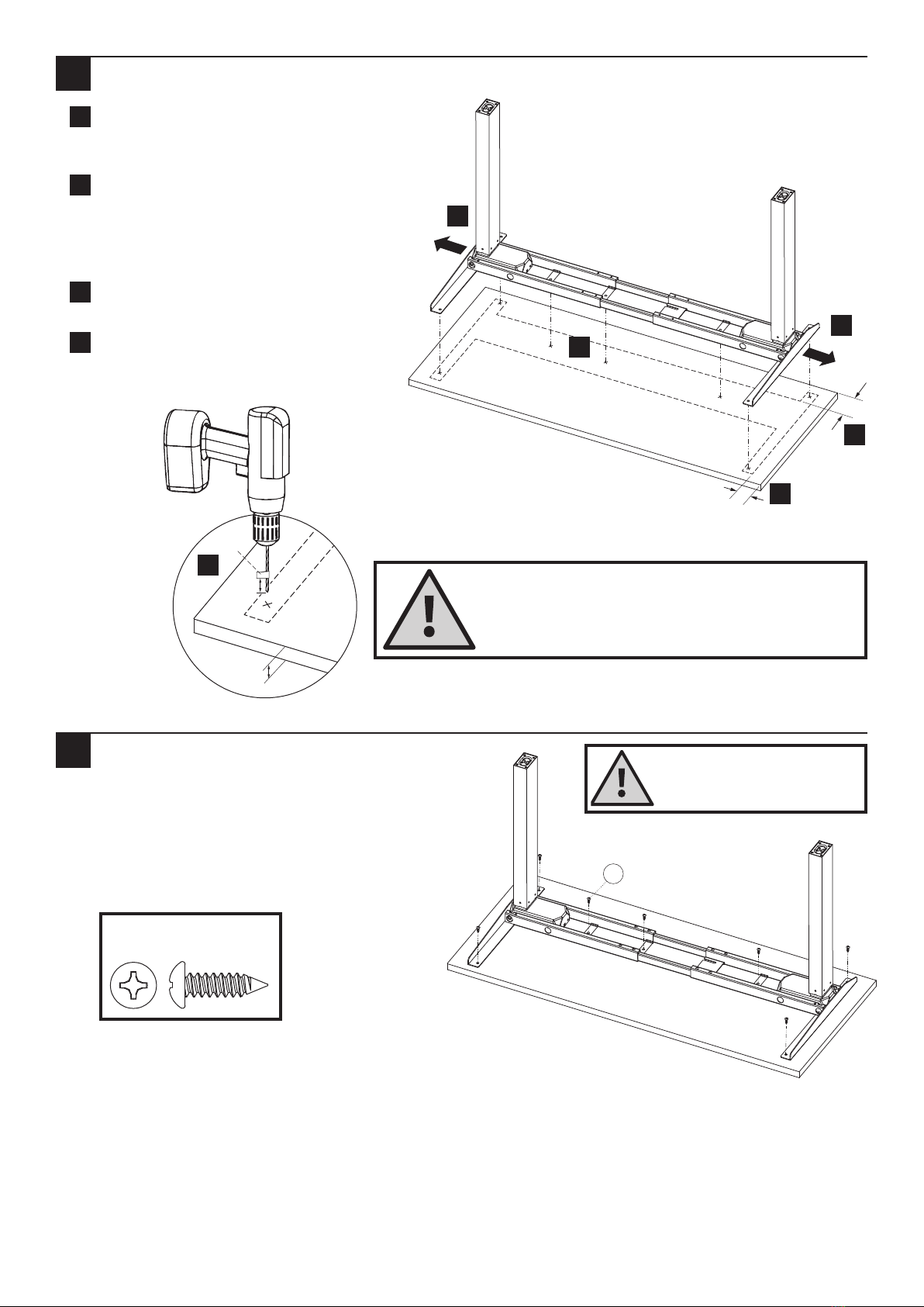
Attach Legs to Frame
Place one of the Legs (B) into the Frame End
(A).
Line up the holes on the Legs (B) with the
holes on the Frame (A) ends.
Insert four #M6 × 10 mm Allen Head Screws
(L) through the holes in the Frame End going
into the Leg and tighten securely with the
supplied Allen Wrench (J).
Repeat for the other Leg.
Attach Side Brackets
The Frame end with the Control Box
bracket should be placed on the side of the
desk where you plan to mount the Switch
(G) and Control Box (F). The example shows
a Switch on the le.
Note: Le will be right and vice versa
when viewing the frame upside down.
Slide the Side Brackets (C & D) into the
Frame ends until flush. Insert two M6 × 14
mm Allen Head Screws (K) through the
holes in the Brackets and into the Frame.
Using the supplied Allen Wrench, rotate
each screw just a few turns. Aer both
M6×14 mm Allen Head Screws are
inserted, tighten both screws securely.
Repeat for the other side of the Frame
assembly.
2
1
B
A
L
L
J
B
To avoid stripping the threads, always
insert and make the first few turns
of the screw BY HAND with an Allen
wrench (H), ensuring it is in straight.
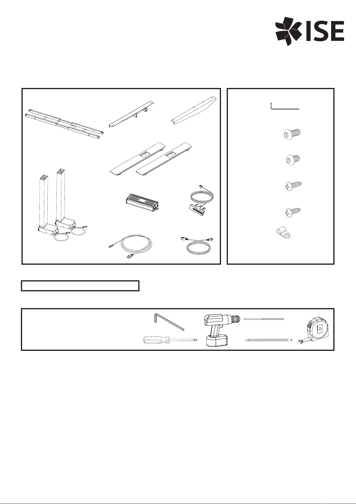
L#M6 × 10mm Allen
Head Screw
KM6 × 14 mm Allen
Head Screw
Hardware at actual size
Control Box Bracket on le
when flipped right side up
Rotate for Switch on right
prior to adding Brackets
Switch on le
C
D
K
K
Note: Legs are shown without
cables for clarity.

4 of 8 ISE | (800) 463-7731 www.ise-group.com
Adjust Frameset to Width of Worksurface
Adjust the width of the Frame assembly
to fit the worksurface by sliding the two
halves outward.
Position to leave at least .5" of the
worksurface width on each end beyond
the frame width and 5.75" from the back
of the Worksurface to the back of the
Frame.
Mark the position of the seven mounting
holes on the bottom of the worksurface.
CAREFULLY drill pilot holes at the nine
locations. Do not drill all the way
through your worksurface!
Attach Frame Set to Worksurface
Double-check that the desk base is properly
positioned over the pilot holes.
Attach the desk base to the underside of the
desktop using seven #12 × " Phillips Head
Wood Screws (M).
.5"
minimum
5.75"
½"
at least 1"
mark
.5"
minimum
5.75"
½"
at least 1"
mark
.5"
minimum
5.75"
½"
at least 1"
mark
3
4
M
M#12 × " Phillips Head
Wood Screw
Hardware at actual size
Double-check that the wood screws
are not too long for your desktop
and won’t puncture the surface
when screwed all the way in.
DO NOT DRILL ALL THE WAY THROUGH THE WORKSURFACE!
You may want to mark your drill bit so that you do not drill all
the way through your worksurface! These instructions and the
hardware included assume that you are using a standard 1" thick
worksurface. If you have a worksurface that is thinner than 1", you
will need to use dierent fasteners to attach your frame.
a
b
c
da
a
b
b
d
c

ISE | (800) 463-7731 www.ise-group.com 5 of 8
Lock Frame Width
Lock the position of the Frame using eight
M6×10Allen Head Screws (L) using the Allen
Wrench.
Attach Feet
Attach the Feet (E) with four M6 × 14 mm
Allen Head Screws (K) and tighten in a cross-
pattern.
NOTE: The longer portion of the Foot faces
the front.
.5"
minimum
5.75"
½"
at least 1"
mark
LM6 × 10 mm
Allen Head Screw
Hardware at actual size
Ensure that the #M6 × 10 mm
Allen Head Screws (L) contacts the
Center Rails by sliding the Center
Rails as needed.
5
6
E
E
K
K
L
Longer portion
towards front
Center Rails
KM6 × 14 mm Allen
Head Screw
Hardware at actual size

6 of 8 ISE | (800) 463-7731 www.ise-group.com
Attach Control Box & Connect Cables
Slide the Control Box (F) onto the Control Box Bracket on the Frame.
Connect the cable exiting the Leg (B) closest to the Control directly into the "M2" port on the Control Box (F).
Connect the cable from the other Leg (B) to the "M1" Control Box (F). For workcenters with widths greater
than 72" you may need to use the Leg Extension Cord (I) to reach the Control Box.
Connect the Switch (G) cable to the "HS" port on the Control Box (F).
Connect the Power Cord (H) to the "AC" port on the Control Box (F).
Use the adhesive-backed Cable Clips (O) to secure all cables so they stay up and out of the way.
Attach Switch
Attach the Switch (G) into pre-drilled holes,
or flush with the front desktop edge (or
recessed up to ".) Place the Switch toward
an end so it does not interfere with your chair
when seated. Use two #12 × " Phillips
Head Wood Screws (N) to attach. Do not
overtighten!
a
a
b
c
d
e
e
d
c
B
B
F
H
G
8
Control Box Bracket
B
H
B
G
"AC"
"M1"
"HS"
G
N
7
N#12 × " Phillips Head
Wood Screw
Hardware at actual size
Do not overtighten screws
in this step. Overtightening
could cause damage to the
component.
b
F
"M2"

ISE | (800) 463-7731 www.ise-group.com 7 of 8
Put Workcenter Upright and Connect Power Cord to the Power Supply
With the Workcenter at its lowest height, turn the assembled desk right-side up with at least two people.
NOTE: Grab the desk Frame (not the desktop) and turn the desk right-side up.
Plug the Power Cord (H) into a 110 V outlet.
Initialize Legs
Press and hold the DOWN button on the Switch (G) until the desk reaches its lowest height. Release the
DOWN button.
Press and hold the DOWN button again until the LED display reads “RST” or about 10 seconds on non-LED
handset models. Release the DOWN button.
Press and hold the DOWN button a third time until the desk lowers a little bit more, slightly rises and stops.
Release the DOWN button. Your desk is now ready to use.
You must complete this
initialization step or your
workcenter will NOT
function properly.
Cleaning Instructions
To clean the Ascent legs, apply cleaner to a so cloth.
Suggested cleaners: Windex or Formula 409.
Do not use solvents and do not saturate or spray cleaners directly onto workcenter base.
Hold down the down arrow
until workcenter moves slightly
upwards!
Adjust Feet Glides
If necessary, adjust Leveling Glides on workcenter feet to level the worksurface. Unscrew to increase height,
screw in to decrease height.
9
H
a
a
b
b
11
b
c
a
10
✓

8 of 8 ISE | (800) 463-7731 www.ise-group.com
1500233 Rev A
This manual suits for next models
1
Table of contents
Other ISE Indoor Furnishing manuals
Popular Indoor Furnishing manuals by other brands

pottery barn kids
pottery barn kids BELDEN END OF BED DRESSER manual

Frederick York
Frederick York DREXEL FRYDX48NVBG installation guide

Rauch
Rauch M2227 Assembly instructions

Winners Only
Winners Only AC101E Assembly instructions

BDI
BDI SOMA 1133 instruction manual

GFW
GFW MILTON BEDSIDE TABLE quick start guide