isel automation EuroMod F User manual
isel-automation GmbH & Co. KG D-36466 Dermbach Untere Röde 2
+49 (0) 36964 84-500 +49 (0) 36964 84510
FlatCom
GFV
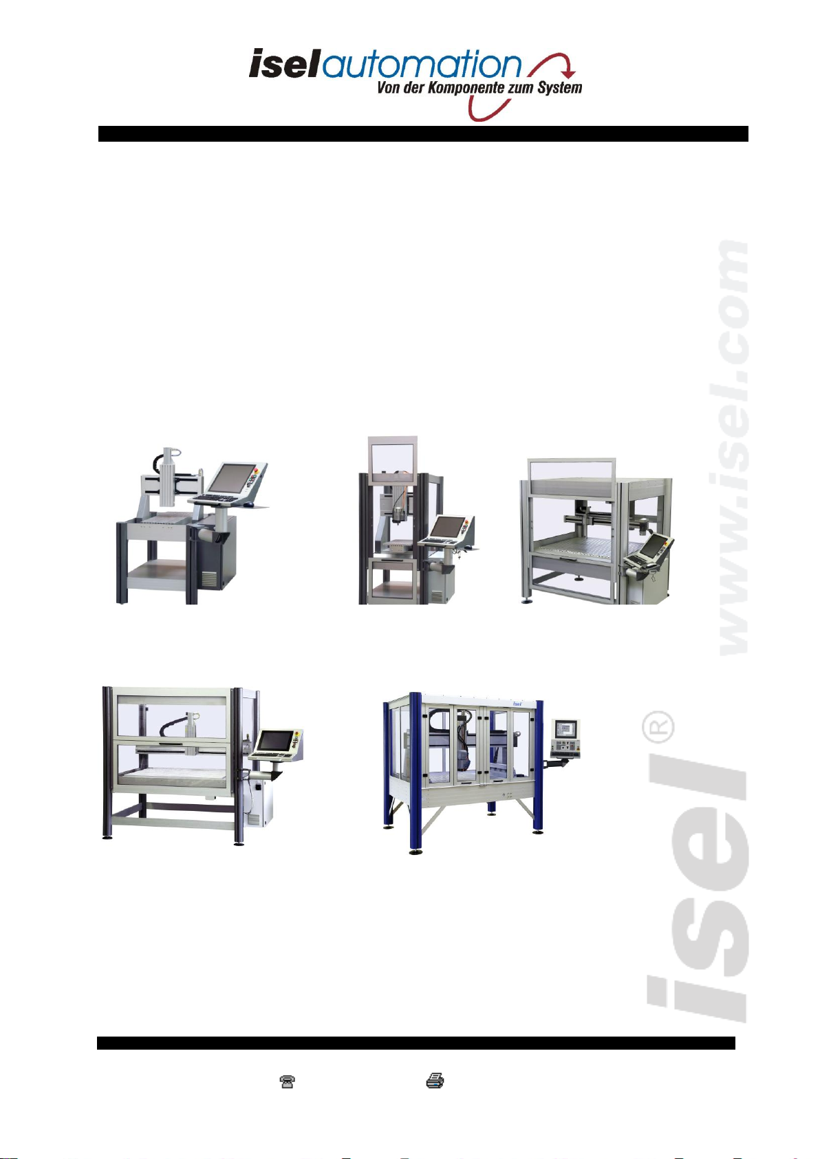
isel –Portal –und Flachbettanlagen
EuroMod F / EuroMod P / FlatCom / OverHead / GFV / GFS
_______________________________________________________
isel - Gantry and Flat-Bed Machines
EuroMod F / EuroMod P / FlatCom / OverHead / GFV / GFS
Betriebsanleitung / Instruction Manual
EuroMod F
EuroMod P
OverHead

About this Manual
Various symbols are to be found in this Manual to indicate quickly important information.
Danger Caution Note Example Additional Information
© iselautomation GmbH & co.KG 2005
All rights reserved
In spite of all care, typographical errors and mistakes cannot be ruled out.
Suggestions for improvement and notes with reference to errors are always welcome.
isel machines and controllers are CE conform and are marked accordingly.
Any other machine parts and components to which the CE safety guidelines
are to be applied must only be commissioned if all relevant
requirements are fulfilled.
isel-automation KG will not assume any liability if you have made any
modifications to the machine.
The EMC test shall only be valid for the original configuration of the machine as delivered
from works.
Manufacturer:isel-automation GmbH & Co.KG
Untere Röde 2
D-36466 Dermbach/Rhön
Tel.: +49 (0) 36964 84-500
Fax: +49 (0) 36964 84-510
E-mail:[email protected]
http://www.isel.com
Art. no. 970371 BD051 10/2005

Table of Contents
1Introduction.........................................................................................................................1
2Use as Prescribed.................................................................................................................2
3Safety Notes..........................................................................................................................3
4Scope of Supply....................................................................................................................4
5Erecting and Connecting the Machine..............................................................................5
5.1 Space requirements ........................................................................................................5
5.2 Transport ........................................................................................................................6
5.3 Erecting the machine......................................................................................................7
5.4 Panelling.........................................................................................................................7
5.5 Wiring.............................................................................................................................8
6Commissioning ....................................................................................................................9
6.1 Preliminary remarks.......................................................................................................9
6.1.1 Coordinate system ................................................................................................................ 9
6.1.2 Assignment of the axes of motion ...................................................................................... 10
6.1.3 Reference point and home position .................................................................................... 10
6.1.4 Clamping the workpiece..................................................................................................... 10
6.1.5 Gantry machines................................................................................................................. 11
6.1.6 Flat-bed machines............................................................................................................... 11
6.2 Cover lock....................................................................................................................12
6.3 Operator panel..............................................................................................................13
6.3.1 Front side operator panel.................................................................................................... 13
6.3.2 Side operator controls......................................................................................................... 14
6.4 Starting the program.....................................................................................................15
6.5 Operating modes ..........................................................................................................16
7Accessories .........................................................................................................................17
7.1 Extraction system (optional) ........................................................................................18
7.2 Cooling / spraying system............................................................................................18
7.3 Tool changer................................................................................................................. 18
8Technical Consulting and Sales .......................................................................................19
9Cleaning and Maintenance...............................................................................................20

10 Faults..............................................................................................................................22
11 Technical Specifications................................................................................................23
11.1 EuroMod P, EuroMod F...............................................................................................23
11.2 GFS/GFV 4433/4473 ...................................................................................................23
11.3 FlatCom........................................................................................................................24
11.4 OverHead .....................................................................................................................25
11.5 GFV..............................................................................................................................25
11.6 Sound pressure level.....................................................................................................25
12 References......................................................................................................................26

isel Gantry and Flat-Bed Machines
Page 1
1Introduction
The isel gantry and flat-bed machines EuroMod P, EuroMod F, OverHead, FlatCom, GFV
and GFS are tried and tested CNC machines, offering a broad variety of possibilities for the
three-dimensional machining of workpieces.
The machines are built and equipped in various sizes and designs. The are based on standard
profiles which are cut to size and can be assembled in different ways, together with drive
elements which are configured according to the particular requirements; the final appearance
of the machine can thus be very different.
All machines have the same interior components, i.e. there is no difference in their general
mechanical design nor in the electrical control system. Each individual machine is tested for
many hours prior to delivery.
To work with the machines described herein, it is imperative to possess basic knowledge in
the CNC technology and in PC applications, as well as a necessary portion of creativity.
Please read these brief instructions now so that you can
• install the machine properly;
• work safely, quickly and efficiently;
• avoid possible hazards to other persons;
• and thus utilise the full performance of the machine.
The instructions given in this Manual refer to the standard scope of supply with which the machine is
ready for operation. You may therefore simply ignore any variants (e.g. accessories and software)
which do not pertain to your machine.
Before installing and commissioning any software or the accessories, please refer also to the
additional manuals and instructions specified in the list of references.

isel Gantry and Flat-Bed Machines
Page 2
2Use as Prescribed
Our gantry and flat-bed machines are CNC-controlled machine tools with several linear axes
and one or two optional rotary axes. The motor output stages are controlled by a PC-based
control system. The control and power electronics for all axes are accommodated *in a control
cubicle by default.
-The CNC machine is designed for use in dry rooms (workshops, laboratories or the
like) and industrial enterprises (max. ambient temperature 40°C).
-The machine is suitable for milling, drilling, cutting, engraving, proportioning,
measuring, positioning and many similar applications.
-You may mount the most varied suitable machining tools or measuring systems for the
applications mentioned above.
-Suitable machining materials are light metal, plastics, wood, glass, p.c. board
materials or the like.
-Materials which produce hazardous gases when processed are deemed to be
impermissible materials.
-The machine is prepared for mounting of an extraction system. This extraction system
is intended for use with dry dust (wood, p.c. boards, etc.).
*The control cubicle is an integral part of the complete systems (but can also be delivered separately
as part of the accessories) and is usually mounted on the right-hand side of the machine frame by
default. The number of motor output stages is configured according to the specific customer
requirements. For systems without control cubicle, only the sections pertaining to the master machine
shall apply.

isel Gantry and Flat-Bed Machines
Page 3
3Safety Notes
- Do not run the machine in an atmosphere subject to the hazard of explosion!
- The machine is enclosed on all sides. The enclosure protects you from moving tools, reduces
the noise level and retains the swarf. The cover is locked and cannot be opened during
machining. This safety device must neither be removed, nor be modified.
- Always ensure that the workpieces are mounted securely.
- The CNC operator panel possesses an EMERGENCY STOP switch for emergency cases,
interrupting the power supply to the power electronics (motor output stages) and to the
frequency converter for the main spindle drive. The shutdown is performed according to Stop
category 1 (controlled shutdown and subsequent interruption of the power supply to the
drives).
-Only qualified and instructed persons are allowed to use the keyswitch on the CNC operator
panel, since the test mode involves an increased injury hazard.
- The spare key must be kept under lock and key.
-Provide for sufficient ventilation in case of dust or gas formation from the machining of the
materials.
-Do not use running water for cooling, but only a cooling system (see "Accessories") which
produces its cooling effect with water mist or air. Make sure that no drips are formed and able
to flow under the clamping plate.

isel Gantry and Flat-Bed Machines
Page 4
4Scope of Supply
The standard scope of supply of our gantry and flat-bed machines includes:
-Aluminium base frame with
opanelling
osuction hose and fittings
-Drive axes including limit switches
-Operator panel including a 17" monitor, a keyboard and a mouse
-Control cubicle including
oMains power cable / line filter
oMain switch
oCable tubing with interconnecting cables 'control cubicle < --> machine'
and 'control cubicle < --> operator panel'
oMotor output stages / servo amplifier
oCNC controller
oSafety circuit module (further referred to as "SC module")
The control software ProNC / Remote including MotionControl software is supplied as an
option.
For the exact scope of delivery of your particular machine, please refer to your
delivery note.

isel Gantry and Flat-Bed Machines
Page 5
5Erecting and Connecting the Machine
5.1 Space requirements
The space required by the machine is limited to its actual footprint and a sufficiently large
area in front of the machine to be able to operate and set up the machine. The cover of the
panelling usually opens upwards and so you must additionally ensure a clearance of approx.
50 to 60 cm above the machine.
This is the operating
position of all gantry and
flat-bed machines.

isel Gantry and Flat-Bed Machines
Page 6
5.2 Transport
Remove the shipping braces from the frame feet. Use only suitable lifting tackle (forklifts,
lifting trolleys - see illustration), lift the machine only from below, and do not pull on the
cover.
When transporting the machine any time later, make absolutely sure that the mains power and
interconnecting cables are not damaged. Always pull out the mains plug first before
transporting the machine.
When transporting the machine, make sure that the machine is not
subjected to strong vibrations.
Always keep the triangular key for manual unlocking of the cover outside
the machine.
This manual suits for next models
5
Table of contents


