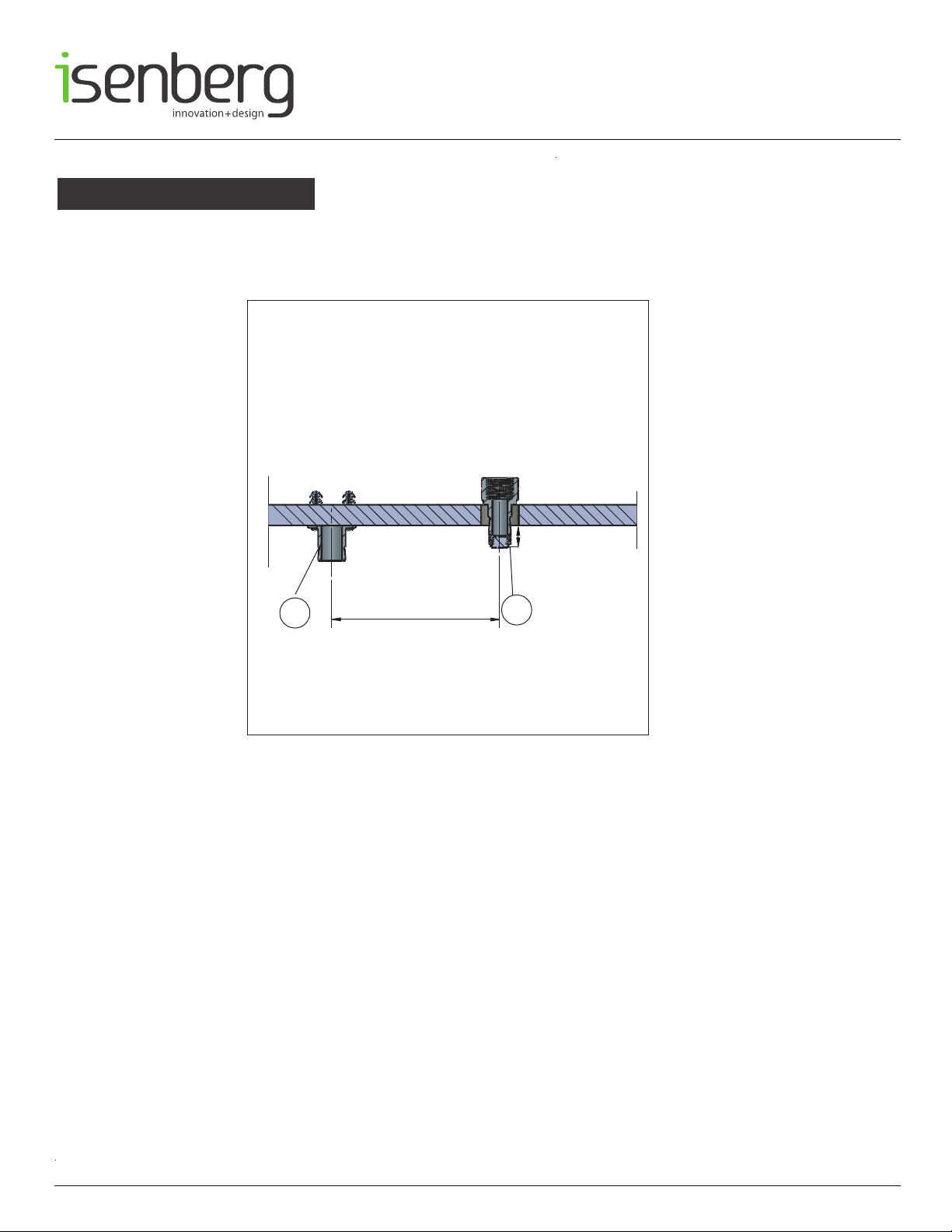
WATERTEMPERATURE
WATERPRESSURE
Thisproductistobeusedwithawater
pressurerangeof15PSIto80PSIONLY
Ifwaterpressureisgreaterthan80PSI
installapressurereducingvalve(PRV)
Thisproductistobeusedwithwaterat
atemperaturerangeof40˚F-120˚F
ONLY!
www.isenbergfaucets.com
OPERATINGSPECIFICATIONS
1
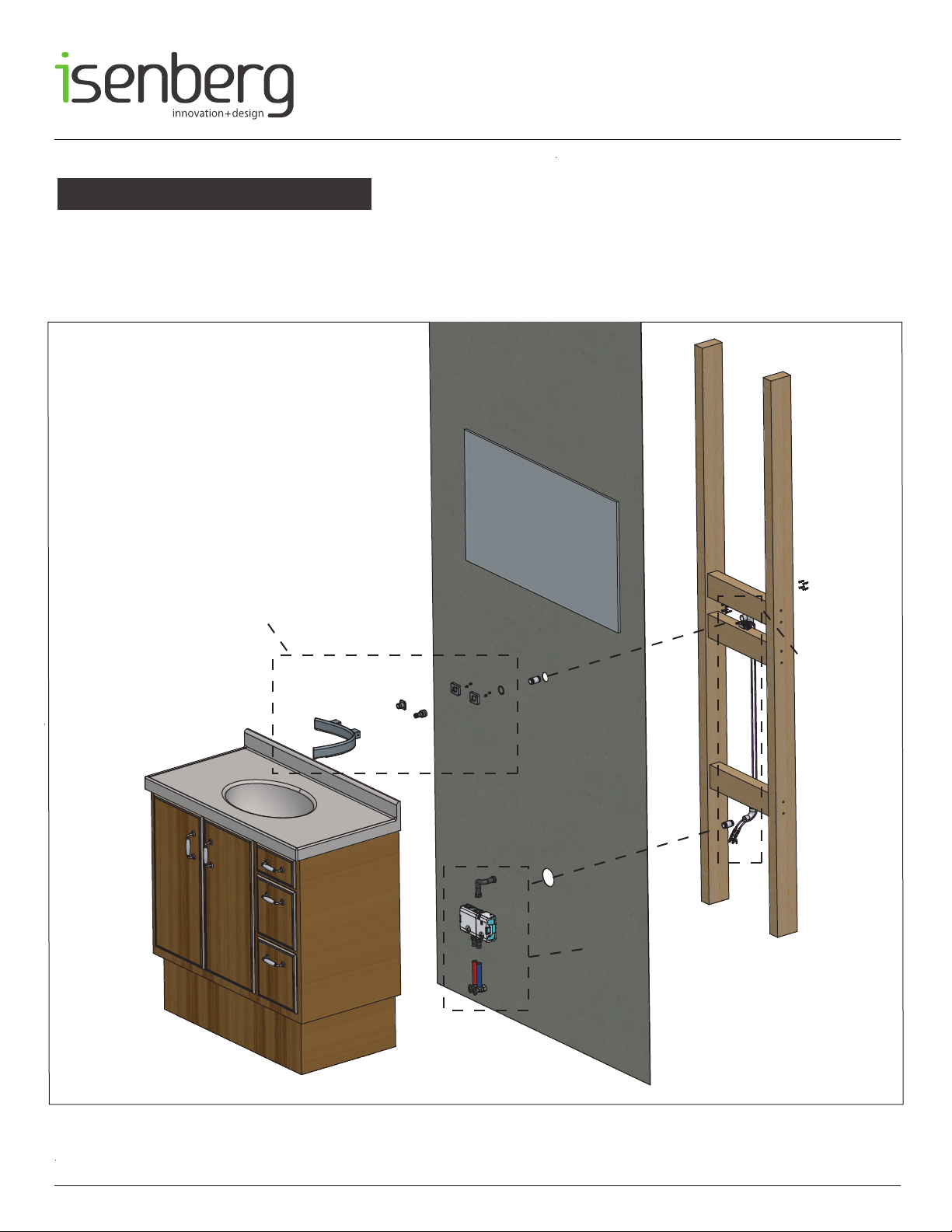
NOTICETOHOMEOWNER
•
We
recommendthatthisproductisinstalledbyaqualified
professionalplumber.
•Pleasecheckthisproductimmediatelytoensurethatithas
notbeendamagedandiscomplete.Beforeinstallation,please
makesurethisproductisthecorrectmodelandyouhaveall
thepartsrequiredforinstallationanduse.
•Pleaseflushthewatersystemtoensurethatnometalswarf,
solder,andotherimpuritiescanentertheproduct.
•
Turnoffwatersupplybeforecommencingwork.
•Pleasereadtheseinstructionscarefullyandretainforfuture
reference.