Tableofcontents
User’sManualiii
Table of Contents
1.SECURITY ADVICE AND WARNINGS ________________________________________1
1.1 Welcome--------------------------------------------------------------------------------------------- 2
1.2 Introduction----------------------------------------------------------------------------------------- 2
1.3 Health and safety----------------------------------------------------------------------------------- 2
1.4 Safety warnings and instructions for use-------------------------------------------------------- 2
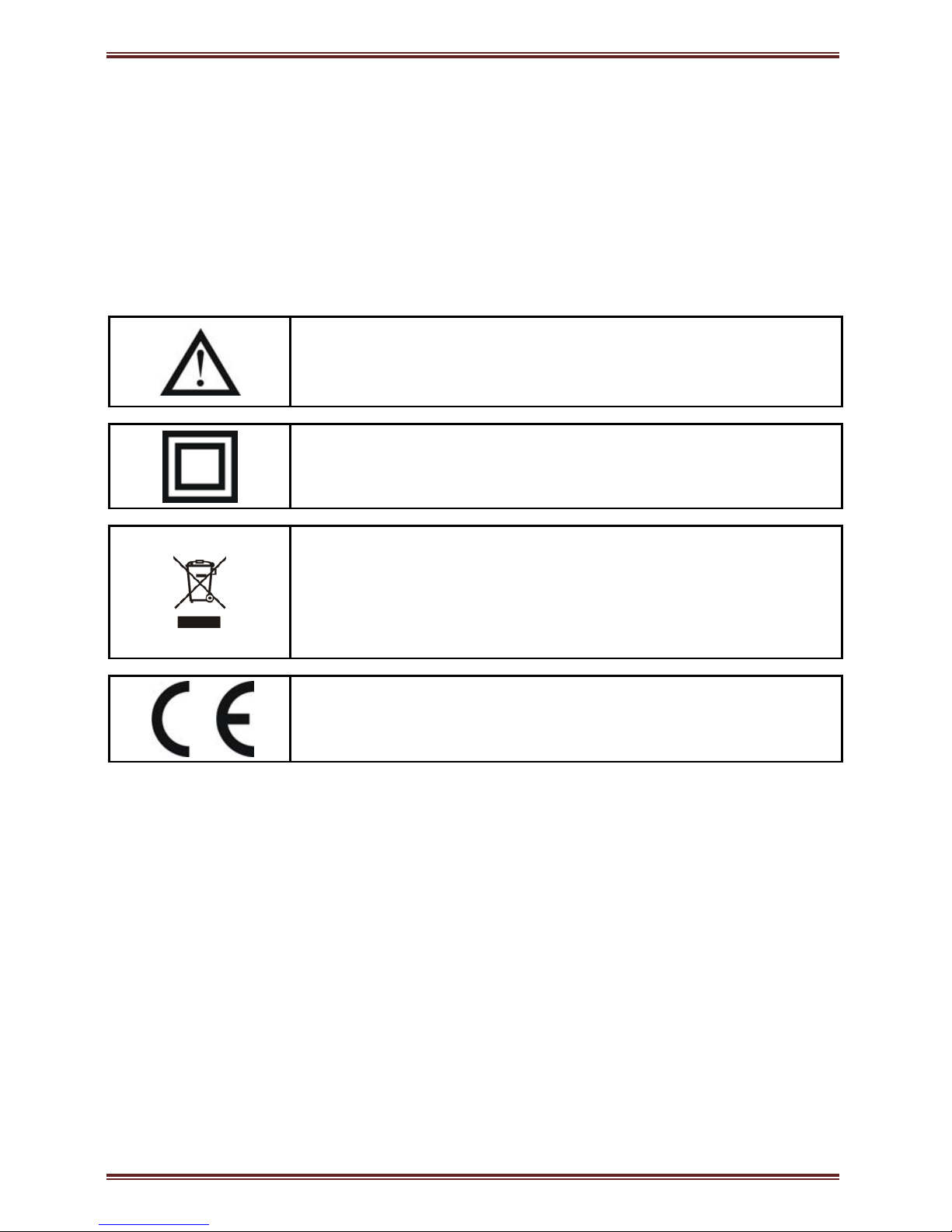
1.5 Warnings, information and notes regarding designation of the product ------------------- 3
2.BASIC DESCRIPTION AND OPERATION OF MEASURING TRANSDUCER _________4
2.1 Introduction----------------------------------------------------------------------------------------- 5
2.2 Glossary --------------------------------------------------------------------------------------------- 5
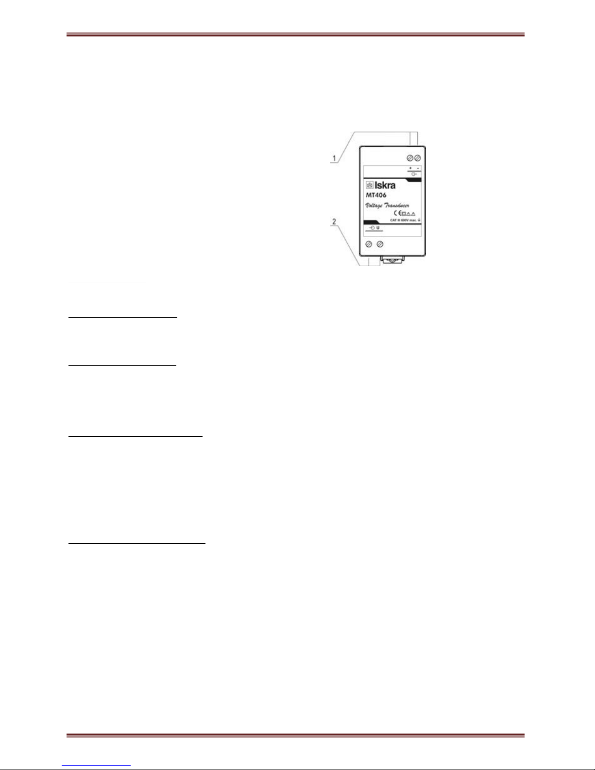
2.3 Description of the product ------------------------------------------------------------------------ 6
2.4 Purpose and use of measuring transducer------------------------------------------------------ 6
3.CONNECTION ___________________________________________________________7
3.1 Introduction----------------------------------------------------------------------------------------- 8
3.2 Mounting -------------------------------------------------------------------------------------------- 8
3.3 Electric connection--------------------------------------------------------------------------------- 8
4.TECHNICAL DATA_______________________________________________________10
4.1 Applied standards---------------------------------------------------------------------------------11
4.2 Accuracy--------------------------------------------------------------------------------------------11
4.3 Measuring input-----------------------------------------------------------------------------------12
4.4 Measuring output----------------------------------------------------------------------------------12
4.5 Connection -----------------------------------------------------------------------------------------12
4.6 Safety features -------------------------------------------------------------------------------------13
4.7 Mechanical-----------------------------------------------------------------------------------------13
4.8 Environmental conditions------------------------------------------------------------------------13
4.9 Dimensions-----------------------------------------------------------------------------------------13