Iskra MI 436 User manual

User's Manual
Measuring Transducer
MI 436

2 User's Manual MI 436

User's Manual MI 436 3
List of contents:
1. CONTAINS OF DELIVERY ________________________________________________________ 4
2. SAFETY ________________________________________________________________________ 4
2.1 EXPLANATION OF SYMBOLS AND LABELS _____________________________________ 4
2.2 WARNINGS, REGULAR INFORMATION AND REMARKS REFERRING TO CE-MARKING4
3. INTRODUCTION _________________________________________________________________ 5
3.1 FEATURES ___________________________________________________________________ 5
3.2 APPLICATION ________________________________________________________________ 5
3.3 LAYOUT AND MODE OF OPERATION ___________________________________________ 6
3.4 PROGRAMMING ______________________________________________________________ 6
3.5 VERSIONS ___________________________________________________________________ 7
4. TECHNICAL DATA_______________________________________________________________ 7
4.1 GENERAL____________________________________________________________________ 7
4.2 INPUT _______________________________________________________________________ 7
4.3 ANALOGUE OUTPUT__________________________________________________________ 8
4.4 ACCURACY __________________________________________________________________ 8
4.5 POWER SUPPLY ______________________________________________________________ 8
4.6 COMMUNICATION (OPTIONAL) ________________________________________________ 9
4.7 HOUSING ____________________________________________________________________ 9
4.8 CONECTION TERMINALS______________________________________________________ 9
4.9 ENVIRONMENTAL CONDITIONS ______________________________________________ 10
4.10 EU DIRECTIVES CORRESPONDING FOR CE MARKING __________________________ 10
5. MOUNTING ____________________________________________________________________ 10
6. CONNECTION __________________________________________________________________ 10
6.1 CONNECTION TABLE ________________________________________________________ 11
6.2 DIMENSIONAL DRAWING ____________________________________________________ 12
6.3 MARKING __________________________________________________________________ 12

4 User's Manual MI 436
1. CONTAINS OF DELIVERY
The delivery contains:
•Measuring transducer MI 436
•User’s manual
2. SAFETY
This Safety Section should be read before
commencing any work on the equipment
•Protection: Protection class II
300 V rms, installation category III
600 V rms, installation category II
pollution degree 2
•Test voltage: 3.7 kV rms
according to EN 61010-1: 1990
The information in the Safety Section of the
product documentation is intended to ensure
that products are properly installed and handled
in order to maintain them in a safe condition. It
is assumed that everyone who will be
associated with the equipment will be familiar
with the contents of the Safety Section.
2.1 EXPLANATION OF SYMBOLS
AND LABELS
The meaning of symbols and labels which may
be used on the equipment or in the product
documentation is given below.
ACaution: refer to product
documentation
.Caution: risk of electric shock
Functional earth terminal
Note: this symbol may also be used for a
protective/safety earth terminal if that terminal
is part of a terminal block or sub-assembly e.g.
power supply.
2.2 WARNINGS, REGULAR
INFORMATION AND REMARKS
REFERRING TO CE-MARKING
In this manual installations and working
instructions for the measuring transducer MI
436 is to be found. Installation as well as use of
the measuring transducer will involve working
with dangerous currents and voltages.
Professionals must handle these areas. Iskra
MIS d.d. does not take on responsibility for the
use and installation. If any doubt comes up
concerning the installation or use of the system,
on which the measuring transducer is to be used
for measurement, the person responsible for the
power installation should be contacted.
Measuring transducer MI 436 is CE-marked
according to the LV-directive and EMC-
directive for housing and light industry, which
normally covers the most common use of the
measuring transducer.

User's Manual MI 436 5
Before energising the equipment, the
following should be checked:
•Voltage rating and polarity
•Protective fuse rating (the recommended
maximum rating of the external
protective fuse for this equipment is 6A
- Red Spot type or equivalent);
•Integrity of earth connection (where
applicable)
Waste disposal site
Waste electrical and electronic equipment shall
not be handed over to a local waste disposal
company or be disposed of as unsorted
municipal waste. The electrical and electronic
equipment producer or purchaser shall at the
end user's request collect waste electrical and
electronic equipment free of charge provided
the electrical and electronic was put on the
market by it. Waste electrical and electronic
equipment does not fall within the scope of old
waste electrical and electronic equipment load.
The treatment after the expired life shall
comply with provisions of the Directive
2002/96/EC, or Regulations on Management
Treatment of Waste Electrical and Electronic
Equipment (Official Journal of the Republic of
Slovenia No. 118/04).
3. INTRODUCTION
3.1 FEATURES
•Measuring of true RMS AC voltage
•Programmable input and output
•Low power consumption
•Universal AC/DC Auxiliary power
supply
•Accuracy class: 0.5
•Serial communication RS232 or RS485
very high speed data rate: up to 115,200
bit/s, (MODBUS protocol)
•Housing for DIN rail mounting
•Up to three analogue outputs
3.2 APPLICATION
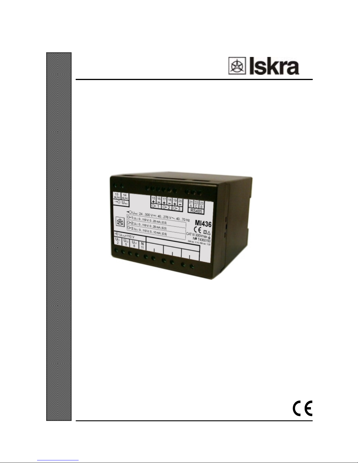
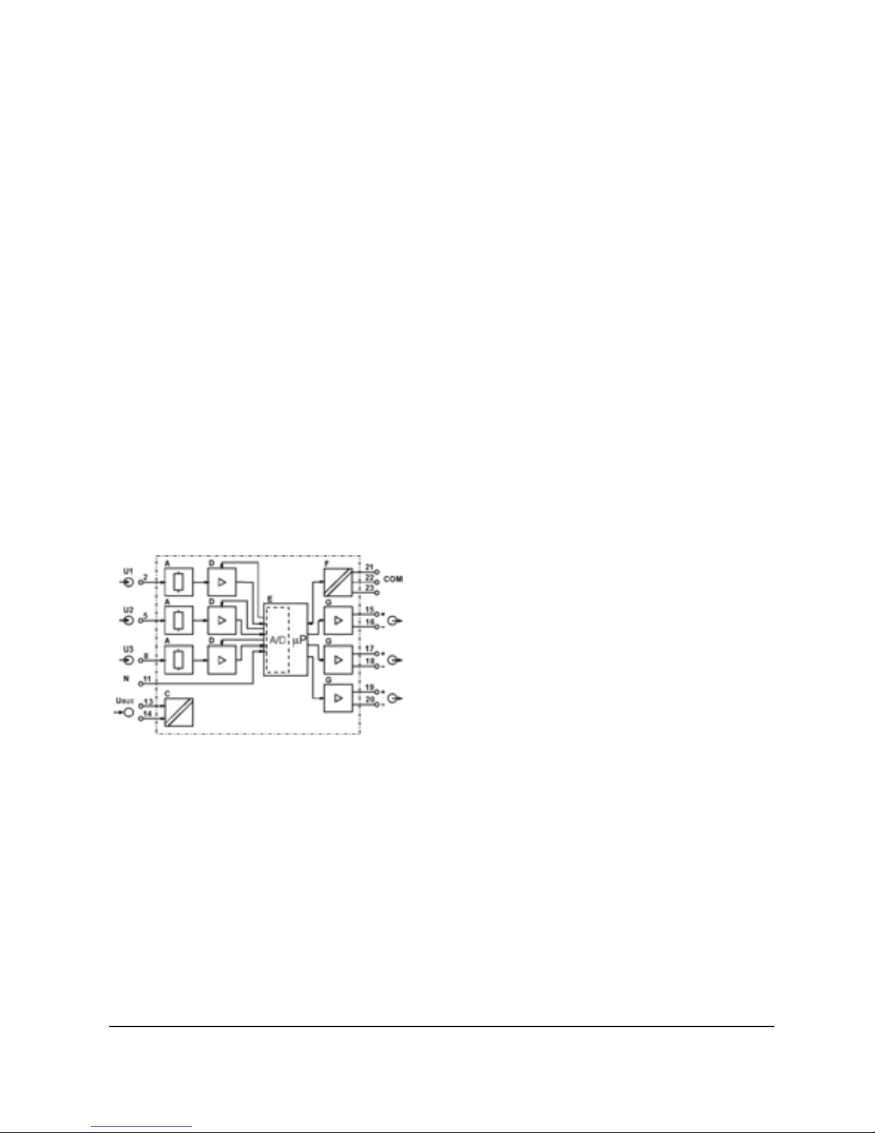
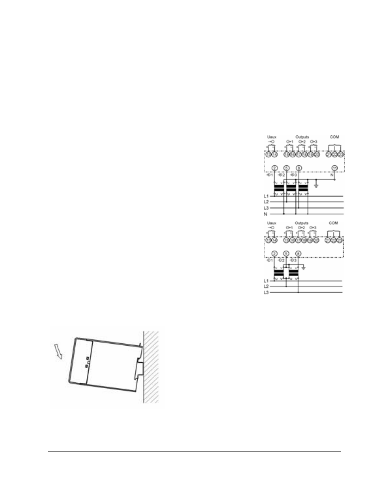
Programmable measuring transducer MI436
allows simultaneous measuring of three
voltages of the same frequency with common
zero (three phase system). Large input range
allows use for measuring of any standard AC
voltage. It generates 3 electrically insulated,
load independent analogue output signals (DC
voltage or DC current). The analogue output
signal is proportional to the measured value and
it is appropriate for the control of analogue and
digital devices.
The ease of programmability of transducer is an
important feature in the provision of cost
effective system control. Systems can be easily
changed or expanded as required.

6 User's Manual MI 436
3.3 LAYOUT AND MODE OF
OPERATION
Voltages are measured by the resistor voltage
divider A (Picture 1) and than amplified in
programmable amplifier D. After A/D
conversion the signal is computed in
microprocessor E. The MI436 uses a true RMS
measurement technique, which provides
accurate measurement. It extracts 64 samples
per cycle and the true RMS measurement is
obtained using these sampled values. The
measured value determined by the
microprocessor is assigned to the three
programmable analogue outputs G.
Communication F enables programming of the
measuring transducer and monitoring of the
following measuring values:
•True RMS input voltage
(phase to neutral and phase to phase)
•%THD
Picture 1: Block diagram
3.4 PROGRAMMING
Input and output values are programmed1) by
setting software2) via RS232 or RS485
communication. Before setting the transducer,
output value must be selected by the jumpers on
the output module3). It is possible to choose
between ranges -1…0…1 V, -10…0…10 V,
-1…0…1 mA, -5…0…5 mA and -
20…0…20 mA. Within this three ranges is
possible to set any linear or bent (with
maximum 5 break points) output characteristic.
1)– Programming is not possible in versions without communication
2) – Software for setting the transducer is available on the web site of the
company free of charge
3) – Qualified person only

User's Manual MI 436 7
3.5 VERSIONS
The following transducer versions are available (Table 1).
Input Frequency Output Communication Bent characteristic of analogue
output
Programmable 500 V 50 / 60 Hz
5 mA
20 mA
10 V
RS232 or RS485 Programmable via
communication
Fixed
configuration
57,74 V
63,5 V
100 V
110 V
230 V
250 V
400 V
500 V
on request
from 50 V to 600
V
50 / 60 Hz
5 mA
10 mA
20 mA
4...20 mA
10 V
other on request
RS232 , RS485
or without
communication
To be specified at the placing
order
Table 1: Versions of MI436
Transducers are mounted on standard rail 35 x 15 mm (according to SIST EN 60715).
4. TECHNICAL DATA
4.1 GENERAL
•Measured quantity: AC voltage
•Measured principle:
True RMS value measurement
microprocessor sampling
4.2 INPUT
•Programmable ratings:
Measuring range limit values:
0…50 V to 0…500 V
•Nominal frequency fN: 50/60 Hz
•Frequency range: 45…65 Hz
•Consumption: U2/ 3 MΩ
•Overload capacity:
according to EN 60688: 1992
Measured
quantity
UN
Number of
applications
Duration
of one
application
Interval
between
two
successive
applications
1,5 x Un ⎯continuously ⎯
2 x Un 10 1 s 100 s
Table 2: Overload capacity

8 User's Manual MI 436
4.3 ANALOGUE OUTPUT
Programmable DC current output:
•Output IOutN (output range end value):
Output range values4): –100…0…100%
(-1…0…1 mA) to –20…0…20 mA
•Burden voltage: 15 V
•External resistance:
RBmax.[kΩ]=
[mA
]
I
V15
OutN
4) - Depends of set jumpers on output module
Programmable DC voltage output:
•Output UOutN (output range end value):
Output range values –100…0…100%
-1…0…1 V do –10…0…10 V
•Burden current: 20 mA
•External resistance:
RBmin.[kΩ]=
mA20
[V]UOutN
General:
•Response time: < 300 ms
•Residual ripple: < 1 % p.p.
•Maximum output value:
limited at 125 % analogue output signal
The output may be either short or open-
circuited and it is electrically insulated from all
other circuits (floating).
All the output range end values can be reduced
subsequently using the programming software,
but a supplementary error results.
4.4 ACCURACY
•Reference value: Input end value
•Accuracy class 5):
Analogue output: Voltage 0.5 c
Communication: Voltage 0.5
THD 1
5) – To calculate intrinsic error, see chapter intrinsic-error (for analogue
outputs) on this page.
Reference conditions:
•Ambient temperature: 15…30 °C
•Input: (connected to the measuring
transformer) 0…100 % UN
•Crest factor: √2
Intrinsic-error (for analogue outputs):
For intrinsic-error for analogue outputs with
bent or linear-zoom characteristic multiply
accuracy class with correction factor (c).
Correction factor c (the highest value applies):
Linear characteristic
e
e
x
x
y
y
c0
0
1
1
−
−
=
or 1=c
Bent characteristic
bb xxx
≤
≤
−1b– number of break
point (1 to 5)
e
e
bb
bb
y
x
xx yy
c⋅
−
−
=
−
−
1
1or 1=c
Picture 2: Examples of settings with linear and
bent characteristic
4.5 POWER SUPPLY
Auxiliary AC/DC voltage (universal):
•Rated voltage (Ur): 24…300 V DC
40…276 V AC
•Frequency range: 40…70 Hz
•Power consumption: < 3 VA

User's Manual MI 436 9
4.6 COMMUNICATION
(OPTIONAL)
RS232
•Connection type: Point to point
•Signal levels: RS232
•Maximum cable length: 15 m
•Connector: Screw terminals
•Isolation: 3.7 kV rms for 1 minute
between all terminals and all other circuits,
except between communication terminals
and output terminals, 2 kV rms for 1 minute
•Transmission mode: Asynchronous
•Message format: MODBUS RTU
•Data rate (very high speed):
1,200 to 115,200 bits/s
•RS232 connections
MI 436
9 pin D
connector (PC)
25 pin D
connector (PC)
Rx (21) Tx (3) Tx (2)
(22) GND (5) GND (7)
Tx (23) Rx (2) Rx (3)
Table 3: RS232 connections
RS485
•Connection type: Multi-drop
(32 connections per link)
•Signal levels: RS485
•Cable type: Screened twisted pair
•Maximum cable length: 1000 m
•Connector: Screw terminals
•Isolation: 3.7 kV rms for 1 minute
between all terminals and all other circuits,
except between communication terminals
and output terminals, 2 kV rms for 1 minute
•Transmission mode: Asynchronous
•Message format: MODBUS RTU
•Data rate (very high speed):
1,200 to 115,200 bits/s
•RS485 connections
MI 436 RS485
A (21) DATA A
C (22) NP 6)
B (23) DATA B
Table 4: RS485 connections
6) – NC – do not connect
4.7 HOUSING
•Material of housing: PC/ABS
non-flammable, according to UL 94 V-0
•Mounting:
For rail mounting, 35 x 15 mm
according to SIST EN 60715
•Enclosure protection: IP 50
(IP 20 for connection terminals)
according to EN 60529: 1989
•Weight including packing:
with universal power supply 0,453 kg
4.8 CONECTION TERMINALS
•Permissible cross section of the
connection leads:
≤4.0 mm2single wire
2 x 2.5 mm2fine wire
•Small cross-section cables shall be
equipped with cable conduit. The
minimum conduit diameter required
amounts of 0.14 mm2.

10 User's Manual MI 436
4.9 ENVIRONMENTAL
CONDITIONS
•Climatic rating: Climate class 3
acc. to EN 60688: 1992
•Operating temperature -10 to +55 °C
•Storage temperature -40 to +70 °C
•Annual mean relative humidity:
≤75% r.h.
4.10 EU DIRECTIVES
CORRESPONDING FOR CE
MARKING
Low voltage directive 73/23/EEC: EN 61010-
1: 1993 and EN 61010-A3: 1995 Safety
requirements for electrical equipment for
measurement, control, and laboratory use, Part
1: General requirements
EMC directive 89/336/EEC: EN 61326-1:
1997
Electrical equipment for measurement, control,
and laboratory use EMC requirements, Part 1:
General requirements
5. MOUNTING
MI 436 is appropriate for rail mounting
according to SIST EN 60715.
On picture below you can see rail mounting.
Picture 3: Rail mounting of the transducer
6. CONNECTION
Transducer’s preferential use is connection into
low-voltage network.
To the high-voltage network it can be
connected via high-voltage transformer.
The connection terminals marking can be found
on the front plate.
Picture 4a:
Connection diagram
for three phase four
wire system with
unbalanced load – 4u
Picture 4b:
Connection
diagram for three
phase three wire
system with
unbalanced
load – 3u

User's Manual MI 436 11
6.1 CONNECTION TABLE
Function Connection
UL1 2
UL2 5
UL3 8
Measuring input: AC voltage
N 11
+ 15
Output 1
- 16
+ 17
Output 2
- 18
+ 19
Output:
Output 3
- 20
+ / AC 13
Auxiliary power supply:
- / AC 14
Rx / A 21/21
GND / NC 7) 22/22
Communication: RS232 / RS485
Tx / B 23/23
Table 5: Connections
7) – NC – do not connect

12 User's Manual MI 436
6.2 DIMENSIONAL DRAWING
Picture 5: Dimensional drawing (all
dimensions are in mm)
6.3 MARKING
Measuring transducers with linear
characteristic:
One label at the front of housing (Picture 6):
Picture 6: Example of label for transducer with
linear characteristic
Measuring transducers with bent characteristic:
One label at the front of the housing and
additional label at the top of the housing
(Picture 7):
Picture 7: Example of label for transducer with
bent characteristic


Printed in Slovenia
•
Subject to change without notice •Version 01 / avg. 2006
Table of contents
Other Iskra Transducer manuals
Popular Transducer manuals by other brands

turck
turck interface modul IMC-AIA-11Ex-i/24VDC quick start guide

Raymarine
Raymarine DownVision CPT-70 installation instructions

Deif
Deif TAS-331DG Installation and start-up instructions

norbar
norbar PNEUTORQUE PT 1 Operator's manual

turck
turck LTX-R10 Series manual

Wassp
Wassp WMB-X230 installation manual

GO Systemelektronik
GO Systemelektronik BlueSense manual

Camille Bauer
Camille Bauer Gossen MetraWatt SINEAX DME 401 operating instructions

GE Oil & Gas
GE Oil & Gas T5 installation guide

Guitammer
Guitammer ButtKicker Advancer owner's manual

Seikom Electronic
Seikom Electronic DTM04 user manual

SSET
SSET CE-F01-MS-0.5 Series instructions