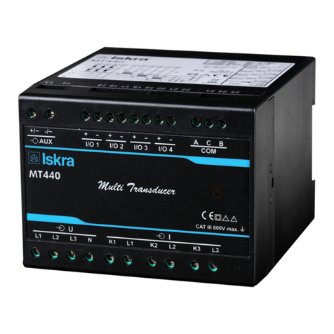
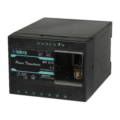
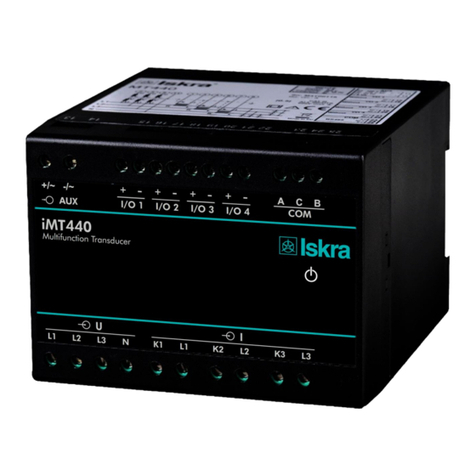
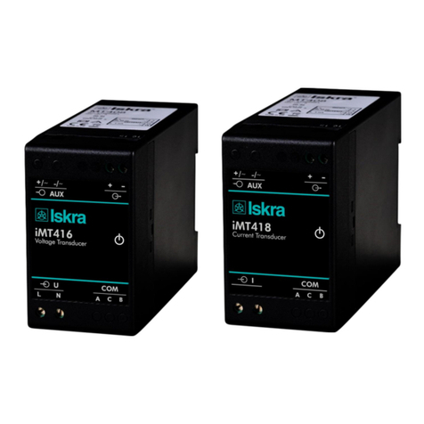
Iskra MT440 User manual

User’s Manual
Multifunction Transducer MT440
GB


Tableofcontents
User’sManualiii
Table of Contents
1.SECURITY ADVICE AND WARNINGS ________________________________________1
1.1 Welcome--------------------------------------------------------------------------------------------- 2
1.2 Introduction----------------------------------------------------------------------------------------- 2
1.3 Health and safety----------------------------------------------------------------------------------- 2
1.4 Safety warnings and instructions for use-------------------------------------------------------- 2
1.5 Warnings, information and notes regarding designation of the product ------------------- 3
2.BASIC DESCRIPTION AND OPERATION OF MEASURING TRANSDUCER _________4
2.1 Introduction----------------------------------------------------------------------------------------- 5
2.2 Glossary --------------------------------------------------------------------------------------------- 6
2.3 Description of the product ------------------------------------------------------------------------ 6
2.4 Purpose and use of measuring transducer------------------------------------------------------ 8
3.CONNECTION ___________________________________________________________9
3.1 Introduction----------------------------------------------------------------------------------------10
3.2 Mounting -------------------------------------------------------------------------------------------10
3.3 Electric connection--------------------------------------------------------------------------------10
3.4 Connection of input/output modules------------------------------------------------------------12
3.5 Communication connection----------------------------------------------------------------------12
3.6 Connection of auxiliary power supply----------------------------------------------------------14
4.SETTINGS ______________________________________________________________15
4.1 Introduction----------------------------------------------------------------------------------------16
4.2 MiQen software------------------------------------------------------------------------------------16
4.3 Setting procedure----------------------------------------------------------------------------------17
4.4 General settings -----------------------------------------------------------------------------------17
4.5 Connection -----------------------------------------------------------------------------------------19
4.6 Communication------------------------------------------------------------------------------------20
4.7 Security ---------------------------------------------------------------------------------------------20
4.8 Energy ----------------------------------------------------------------------------------------------21
4.9 Inputs and outputs---------------------------------------------------------------------------------21
4.10 Alarms---------------------------------------------------------------------------------------------25
4.11 Reset operations ---------------------------------------------------------------------------------25
5.MEASUREMENTS _______________________________________________________26
5.1 Introduction----------------------------------------------------------------------------------------27
5.2 Supported measurements-------------------------------------------------------------------------27
5.3 Available connections ----------------------------------------------------------------------------27
5.4 Explanation of basic concepts-------------------------------------------------------------------29
5.5 Calculation and display of measurements -----------------------------------------------------30
5.6 Present values -------------------------------------------------------------------------------------30

Tableofcontents
ivUser’sManual
6.TECHNICAL DATA_______________________________________________________32
6.1 Applied standards---------------------------------------------------------------------------------33
6.2 Accuracy--------------------------------------------------------------------------------------------34
6.3 Inputs -----------------------------------------------------------------------------------------------35
6.4 Connection -----------------------------------------------------------------------------------------35
6.5 I/O modules ----------------------------------------------------------------------------------------36
6.6 Communication------------------------------------------------------------------------------------37
6.7 Electronic features--------------------------------------------------------------------------------37
6.8 Safety features -------------------------------------------------------------------------------------37
6.9 Mechanical-----------------------------------------------------------------------------------------38
6.10 Environmental conditions ----------------------------------------------------------------------38
6.11 Dimensions ---------------------------------------------------------------------------------------38
7.APPENDIX A: MODBUS PROTOCOL _______________________________________40
7.1 Modbus communication protocol ---------------------------------------------------------------41
8.APPENDIX B: CALCULATIONS & EQUATIONS_______________________________51
8.1 Calculations----------------------------------------------------------------------------------------52
8.2 Equations-------------------------------------------------------------------------------------------53

Securityadviceandwarnings
User’sManual1
1. SECURITY ADVICE AND WARNINGS
1.1 Welcome--------------------------------------------------------------------------------------------- 2
1.2 Introduction----------------------------------------------------------------------------------------- 2
1.3 Health and safety----------------------------------------------------------------------------------- 2
1.4 Safety warnings and instructions for use-------------------------------------------------------- 2
1.5 Warnings, information and notes regarding designation of the product ------------------- 3

Securityadviceandwarnings
2User’sManual
1.1 Welcome
Please read this chapter carefully before starting work with a measuring transducer.
This chapter deals with important information and warnings that should be considered for safe
handling with a measuring transducer.
1.2 Introduction
This booklet contains instructions for installation and use of measuring transducer MT440.
Installation and use of a device also includes handling with dangerous currents and voltages and
shall be therefore carried out by qualified persons. The Iskra MIS Company assumes no
responsibility in connection with installation and use of the product. If there is any doubt
regarding installation and use of the system in which the instrument is used for measuring or
supervision, please contact a person who is responsible for installation of such system.
1.3 Health and safety
The purpose of this chapter is to provide a user with information concerning safe installation and
handling with the product in order to assure its correct use and continuous operation.
It is essential that everyone using the product is familiar with the contents of chapter »Security
Advices and Warnings«.
If equipment is used in a manner not specified by the manufacturer, the protection provided by
the equipment may be impaired.
1.4 Safety warnings and instructions for use
Check the following before switching on the device:
•Nominal voltage,
•Proper connection of auxiliary supply,
•Nominal frequency,
•Voltage ratio and phase sequence,
•Current transformer ratio and terminals integrity,
•Protection fuse - recommended maximal external fuse size is 6 A,
•Proper connection of I/O modules.
Important: A current transformer secondary should be short circuited before connecting the
transducer.
Important: See Chapter 3.3 Electric connection for safety warnings regarding connection.

Securityadviceandwarnings
User’sManual3
Waste
It is forbidden to deposit electrical and electronic equipment as municipal waste. The
manufacturer or provider shall take waste electrical and electronic equipment free of charge. The
complete procedure after lifetime should comply with the Directive 2002/96/EC about restriction
on the use of certain hazardous substances in electrical and electronic equipment.
1.5 Warnings, information and notes regarding designation of the product
Used symbols:
See product documentation.
Double insulation in compliance with the SIST EN 61010−1
standard.
Functional ground potential.
Note: This symbol is also used for marking a terminal for protective
ground potential if it is used as a part of connection terminal or
auxiliary supply terminals.
Compliance of the product with directive 2002/96/EC, as first
priority, the prevention of waste electrical and electronic equipment
(WEEE), and in addition, the reuse, recycling and other forms of
recovery of such wastes so as to reduce the disposal of waste. It also
seeks to improve the environmental performance of all operators
involved in the life cycle of electrical and electronic equipment.
Compliance of the product with European CE directives.
Contents of consignment
The consignment includes:
−Measuring transducer MT440,
−label for I/O functionality description,
−quick guide.

Basicdescriptionandoperationofmeasuringtransducer
4User’sManual
2. BASIC DESCRIPTION AND OPERATION OF MEASURING
TRANSDUCER
2.1 Introduction----------------------------------------------------------------------------------------- 5
2.2 Glossary --------------------------------------------------------------------------------------------- 6
2.3 Description of the product ------------------------------------------------------------------------ 6
2.4 Purpose and use of measuring transducer------------------------------------------------------ 7

Basicdescriptionandoperationofmeasuringtransducer
User’sManual5
2.1 Introduction
Description of symbols
In different chapters or tables different symbols may appear in User’s Manual. According to the
position of symbols, they have different meaning.
Subchapter
Symbols next to the subchapters indicate accessibility of functions described. Accessibility of
functions is indicated with the following symbols:
−Function accessible via communication (MiQen software)
Tables
Supported functions and measurements are listed in tables. Symbols in tables indicate support of
enabled functions. Additionally a legend is placed below table of used symbols. Meaning of
symbols is:
●−Function is supported
× −Function is not supported
○−Symbol meaning varies and is described in the legend below the table
User information
For unknown technical terms please refer to Glossary on the next page.

Basicdescriptionandoperationofmeasuringtransducer
6User’sManual
2.2 Glossary
Term Explanation
RMS Root Mean Square value
MODBUS Industrial protocol for data transmission
MiQen Software for Iskra MIS instruments
AC Alternating voltage
PA total Angle calculated from total active and apparent power
PA1, PA2, PA3 Angle between fundamental phase voltage and phase current
PF Power factor
THD Total harmonic distortion
MD Measurement of average values in time interval
Hand-over place Connection spot of consumer installation in public network
Mv−Sample factor Defines a number of periods for measuring calculation on the
basis of measured frequency
Mp−Average interval Defines frequency of refreshing displayed measurements on
the basis of a Sample factor
Hysteresis expressed as percentage
[%]
Percentage specifies increase or decrease of a measurement
from a certain limit after exceeding it.
PO Pulse output module
AL Alarm output module
AO Analog output module
FAO Fast analog output module
DO Digital output module
2.3 Description of the product
Measuring transducer is intended for measuring, analyzing and monitoring single-phase or three-
phase electrical power network. It measures RMS value by means of fast sampling of voltage
and current signals, which makes instrument suitable for acquisition of transient events. A built-
in microcontroller calculates measurements (voltage, current, frequency, energy, power, power
factor, THD phase angles, etc.) from the measured signals.

Basicdescriptionandoperationofmeasuringtransducer
User’sManual7
Appearance
Measuring transducer can differ from yours depending on the type and functionality.
1 – Communication ports
2 – I/O modules
3 – Auxiliary supply
4 – Voltage inputs
5 – Current inputs
6 – Power ON LED
Communication ports and LED indicators
Serial communication can be connected by using screw-in connector (RS232 or RS485). USB
can be connected through USB-mini type connector at the bottom of transducer.
LED indicator is intended for POWER ON signaling (red LED).
Warning!
USB communication port is provided with only BASIC insulation and can
ONLY be used unconnected to aux. supply AND power inputs!
I/O modules
Four I/O module slots are intended for various I/O modules, which should be chosen at placing
the order. Analog outputs, fast analog outputs, relay outputs (alarm, pulse, general-purpose
digital outputs) and solid-state relay outputs (alarm, pulse, general-purpose digital outputs).
Universal auxiliary supply
Auxiliary supply is connected by two screw-in connectors. For safety purposes it is important
that all wires are firmly fastened. Auxiliary supply is wide range (24 VDC – 300 VDC; 40 VAC –
276 VAC).
Voltage inputs
Each voltage input is connected to measuring circuit through input resistor chain (3.3 MΩper
phase). Maximum value of input voltage is 600 VL-N (1000 VL-L).
Current inputs
Each current input is connected to measuring circuit through current transformer (0.01Ωper
phase). Maximum allowed thermal value of input current is 15A (cont.).

Basicdescriptionandoperationofmeasuringtransducer
8User’sManual
2.4 Purpose and use of measuring transducer
The instrument is used for monitoring and measuring electric quantities of three-phase electrical
power distribution system. The meter is provided with 32 program adjustable alarms, up to four
different modules and communication. With the RS232/RS485 and USB communication, the
meter can be set and measurements can be checked. The meter also functions as an energy
counter (up to four energy counters), with the additional function of cost management by tariffs.
Supported measurements
Basic measurements
Phase
Voltage U1, U2, U3and U
~
Current I1, I2, I3, In, Itand Ia
Active power P1, P2, P3, and Pt
Reactive power Q1, Q2, Q3, and Qt
Apparent power S1, S2, S3, and St
Power factor PF1, PF2, PF3and PF~
Power angle φ1, φ2, φ3and φ
~
THD of phase voltage Uf1, Uf2 and Uf3
THD of power angle I1, I2and I3
Phase-to-phase
Phase-to-phase voltage U12, U23, U31
Average phase-to-phase voltage Uf
f
Phase-to-phase angle φ12, φ23, φ31
THD of phase−to−phase voltage
Energy
Counter 1
Counter 2
Counter 3
Counter 4
Active tariff
Other measurements
MD values
Phase current I1, I2, I3
Active power P (Positive)
Active power P (Negative)
Reactive power Q −L
Reactive power Q −C
Apparent power S
Other measurements
Measurements Frequency
Internal temperature

Connection
User’sManual9
3. CONNECTION
3.1 Introduction----------------------------------------------------------------------------------------10
3.2 Mounting -------------------------------------------------------------------------------------------10
3.3 Electric connection--------------------------------------------------------------------------------10
3.4 Connection of input/output modules------------------------------------------------------------12
3.5 Communication connection----------------------------------------------------------------------12
3.6 Connection of auxiliary power supply----------------------------------------------------------14

Connection
10User’sManual
3.1 Introduction
This chapter deals with the instructions for measuring transducer connection. Both the use and
connection of the device includes handling with dangerous currents and voltages. Only a
qualified person shall therefore perform connection. Iskra MIS does not take any responsibility
regarding the use and connection. If any doubt occurs regarding connection and use in the
system, which device is intended for, please contact a person who is responsible for such
installations.
Before use: Check voltages and phase rotation, supply voltage and nominal frequency.
A circuit breaker with current rating of at least 1A shall be included in close proximity with aux.
supply installation as a means of disconnection. It shall be properly marked.
Warning!
Wrong or incomplete connection of supply, measurement or other
terminals can cause malfunction or damage the device.
Note
After connection, settings have to be performed via communication
(connection mode, current and voltage transformers ratio …).
3.2 Mounting
MT440 measuring transducer is designed for DIN rail mounting. It should be mounted on a
35 mm DIN rail by means of two plastic fasteners. Before installation fasteners should be in
open position (pulled). After device is on place, fasteners are locked (pushed) to close position.
3.3 Electric connection
Voltage inputs of measuring transducer can be connected directly to low-voltage network or via
appropriate voltage measuring transformer to medium or high voltage network.
Current inputs of measuring transducer can be connected directly to low-voltage network or via a
corresponding current transformer.
Choose connection from the following figures and connect corresponding voltages and currents.
Information on electrical characteristics is given in the chapter Inputs on page 35.
Warning!
Before using tool for accessing interior or any other part of the transducer
which in normal use may be hazardous live (aux. supply and measuring
input terminals), transducer MUST BE ISOLATED OR
DISCONNECTED from hazardous live voltage.
Note
For proper connection wire diameters and other wiring requirements see
Chaper 6.4 Connection

Connection
User’sManual11
System/ connection Terminal assignment
Connection 1b (1W)
Single-phase connection
Connection 3b (1W3)
Three-phase – three-wire connection with
balanced load
Connection 3u (2W3)
Three-phase – three-wire connection with
unbalanced load
Connection 4b (1W4)
Three-phase – four-wire connection with
balanced load
Connection 4u (3W4)
Three-phase – four-wire connection with
unbalanced load

Connection
12User’sManual
3.4 Connection of input/output modules
Warning!
Check the module features that are specified on the label, before
connecting module contacts. Wrong connection can cause damage or
destruction of module and/or device.
Connect module contacts as specified on the label. Examples of labels are given below and
describe modules built in the device. Information on electrical properties of modules is given in
chapter Modules on page 36.
Electromechanical relay output module. (Example of
alarm module as I/O module 1)
Solid state relay module output. (Example of pulse
module as I/O module 1)
Analog output module with analog output, proportional to
measured quantities. The outputs may be either short or
open-circuited. They are electrically insulated from each
other and from all other circuits. (Example of analog
output module as I/O module 1)
Fast analog output module with analog output,
proportional to measured quantities. The outputs may be
either short or open-circuited. They are electrically
insulated from each other and from all other circuits.
(Example of analog output module as I/O module 1)
3.5 Communication connection
MT440 is equipped with one standard (COM1) serial (RS232 or RS485) communication port
and one service communication port (USB).
Warning!
USB communication port is provided with only BASIC insulation and can
ONLY be used unconnected to aux. supply AND power inputs!
Connect a communication line by means of corresponding terminals. Connection information is
stated on the instrument label. Connector terminals are marked on the label on the upper side of
the instrument.
USB connector is positioned on the bottom side of an instrument under removable plastic cover.
For driver installation see Note on the next page. Instrument will establish USB connection with
PC approx. 3 seconds after physical connection to USB port.
More detailed information about communication is given in chapter Communication on page 37.

Connection
User’sManual13
COM1 serial communication port (RS232)
COM1 serial communication port (RS485)
SERVICE communication port (USB)
RS232
RS232 communication is intended for direct connection of the measuring transducer to the
personal computer. It is necessary to provide the corresponding connection of individual
terminals of the screw terminal connector (see a table below).
RS485
RS485 communication is intended for connection of devices to network where several
instruments with RS485 communication are connected to a common communication interface.
We recommend the use of Iskra MIS communication interfaces for best compatibility!
It is necessary to provide the corresponding connection of individual terminals of the screw
terminal connector (see a table below).
USB
USB communication serves as a fast peer-to-terminal data link. The instrument is detected by
host as a USB 2.0 compatible device. The USB connection is provided through a USB standard
Type mini B connector.
Note
When MT440 is connected to a PC through USB communication for the
first time, a user is prompted to install a driver. The driver is automatically
installed during MiQen software installation. It is also provided on the CD,
enclosed in the original shipment package, or can be downloaded from the
Iskra MIS web page www.iskra-mis.si. With this driver installed, USB is
redirected to a serial port, which should be selected when using MiQen
software.
Warning!
Do not remove USB cover permanently!
The USB port should not remain open. It should be closed immediately after the initial setting
through USB port was done and should remain closed during all time of storing & operation. In
case the customer has not put the cover on the USB after the initial setting was done, before

Connection
14User’sManual
putting to store, mounting the unit on the DIN rail or the unit operates without USB cover the
warranty is void.
Also unit returned back without USB cover or with clear indications that it was stored or
operated without USB cover on the USB port it will be treated as out of the warranty.
Survey of communication connections
Connector Terminals Position RS232 RS485
SCREW
TERMINAL
23 Rx A
24 GND NC
25 Tx B
USB-mini B Standard USB 2.0 compatible cable recommended
(Type mini B plug)
3.6 Connection of auxiliary power supply
Measuring transducer has universal (AC/DC) auxiliary power supply. Information on electric
consumption is given in chapter Technical data on page 32. Auxiliary supply is connected
through screw terminal connector.
Connection of universal power supply to terminals 13 and 14
Warning!
For safety purposes it is important that both wires (Line and Neutral) are
firmly connected.

Settings
User’sManual15
4. SETTINGS
4.1 Introduction----------------------------------------------------------------------------------------15
4.2 MiQen software------------------------------------------------------------------------------------16
4.3 Setting procedure----------------------------------------------------------------------------------17
4.4 General settings -----------------------------------------------------------------------------------17
Description and Location ................................................................................................................. 17
Average interval ............................................................................................................................... 18
Temperature unit .............................................................................................................................. 18
Maximum demand calculation (MD mode) .................................................................................... 18
Starting current for PF and PA (mA) .............................................................................................. 18
Starting current for all powers (mA) ............................................................................................... 18
Minimum synchronization voltage .................................................................................................. 18
Reactive power and energy calculation ............................................................................................ 19
4.5 Connection -----------------------------------------------------------------------------------------19
Connection ....................................................................................................................................... 19
Setting of current and voltage ratios ................................................................................................ 19
Used voltage and current range ....................................................................................................... 19
Nominal frequency .......................................................................................................................... 19
Energy flow direction ...................................................................................................................... 19
CT connection .................................................................................................................................. 19
4.6 Communication------------------------------------------------------------------------------------19
Serial Communication (COM1) ...................................................................................................... 20
USB Communication ....................................................................................................................... 20
4.7 Security ---------------------------------------------------------------------------------------------20
Password setting .............................................................................................................................. 20
Password modification .................................................................................................................... 20
Password disabling .......................................................................................................................... 20
4.8 Energy ----------------------------------------------------------------------------------------------21
Active tariff ...................................................................................................................................... 21
Common energy exponent ............................................................................................................... 21
Counter divider ................................................................................................................................ 21
4.9 Inputs and outputs---------------------------------------------------------------------------------21
Analog output module ..................................................................................................................... 21
Fast analog output module ............................................................................................................... 23
Solid state output module ................................................................................................................ 23
Relay output module ........................................................................................................................ 23
4.10 Alarms---------------------------------------------------------------------------------------------25
Alarms setting........................................................................................................................................ 25
4.11 Reset operations ---------------------------------------------------------------------------------25
Reset energy counters (E1, E2, E3, E4) .......................................................................................... 25
Reset MD values .............................................................................................................................. 25
Reset the last MD period ................................................................................................................. 25
Reset alarm output ........................................................................................................................... 25

Settings
16User’sManual
4.1 Introduction
Instrument settings can be remotely modified with communication (COM1 and/or USB if
available) and MiQen software when connected to a PC.
4.2 MiQen software
MiQen is a software tool for complete monitoring of measuring instruments, connected to a PC
via serial or USB communication. A user-friendly interface consists of five segments: devices
management, instrument settings, real-time measurements and software upgrading.
Two versions of MiQen software are available:
−Professional edition with full functionality and supports all software functionality. CD-Key
is required for the installation.
−Standard edition, freeware edition which supports all software functionality except data
analysis.
For MT440 only standard edition applies since measurement recording and analysis is with
MT440 not supported.
Devices management
Select the instrument in a favorite’s line. Use the network explorer to set and explore the devices
network. Communication parameters of all devices and their addresses in network can be easily
set.
Instrument settings
Multi Register Edit technology assures a simple modification of settings that are organized in a
tree structure. Besides transferring settings into the instrument, storing and reading from the
setting files are also available.
Real-time measurements
All supported measurements can be captured in real time in a table form. For further processing
of the results of measurements, copying via a clipboard into standard Windows formats is
supported.
Software upgrading
Always use the latest version of software, both MiQen and software in the instrument. The
program automatically informs you on available upgrades that can be transferred from the web
site and used for upgrading.
Note
More information about MiQen software can be found in MiQen Help
system!
MiQen user interface
This manual suits for next models
1
Table of contents
Other Iskra Transducer manuals
Popular Transducer manuals by other brands

Baker Hughes
Baker Hughes Masoneilan 8000 instruction manual

LEM
LEM ITZ 2000-SPR FLEX ULTRASTAB manual

Clark Synthesis
Clark Synthesis Prosound429 installation guide

NK TECHNOLOGIES
NK TECHNOLOGIES VTR Series instructions

Johnson Controls
Johnson Controls DP150 Series installation guide

APPA
APPA 30T user manual