4
ME162 ─Electronic single-phase kWh-meter
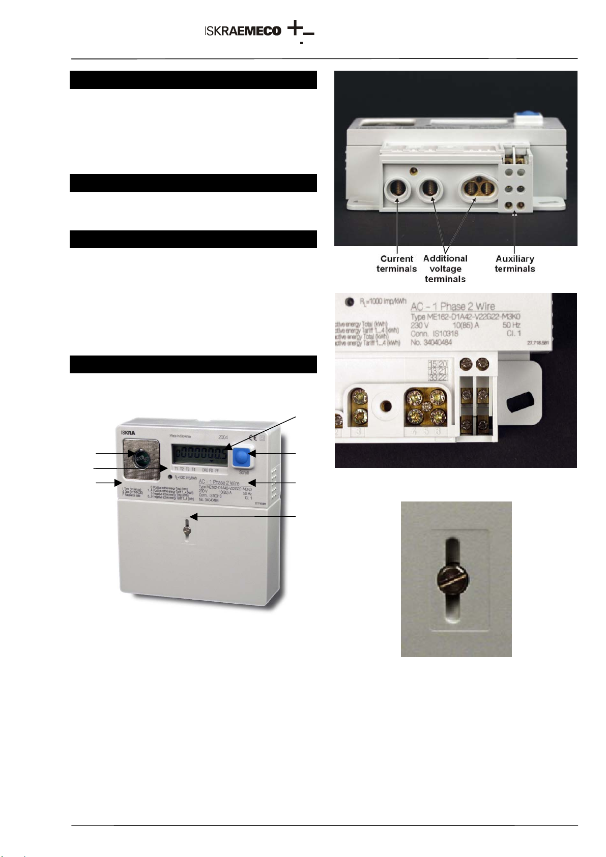
4. Display
Display and indications:
The meter is equipped with a standard LCD.
Fig. 2 - Standard display
Measuring data are displayed with seven 7-segment
8 mm high digits, and one 7-segment 6 mm high
identification numbers.
Symbols indicating energy flow direction, a valid tariff
and meter statuses are also displayed.
4.1. Data display on LCD
Data that are defined in auto scroll and manual scroll
sequences are displayed.
Data are reviewed with a key or they are cyclically
displayed.
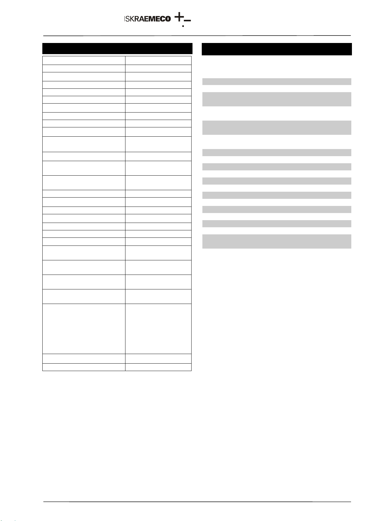
Table 1 – Display of register codes
Notes:
1. (*)The same register code can be used for
different data on a standard display. Register
codes are described on the front plate. At the
same meter type the given register code has
only one meaning.
4.2. Scroll key
The meter is equipped with one mechanical key on
the meter cover.
Key function:
• LCD test
• As an option, data defined in auto scroll and
manual scroll sequences can be displayed even
when there is no voltage in the network or the
meter is not connected.
5. Communication interface
5.1. IR optical port
The meter is provided with an optical port that
enables meter parameter setting and data
downloading.
The optical port complies with the IEC 62056-21 (IEC
61107) standard, a mode C protocol is employed;
data transmission rate is 9600 bit/sec.
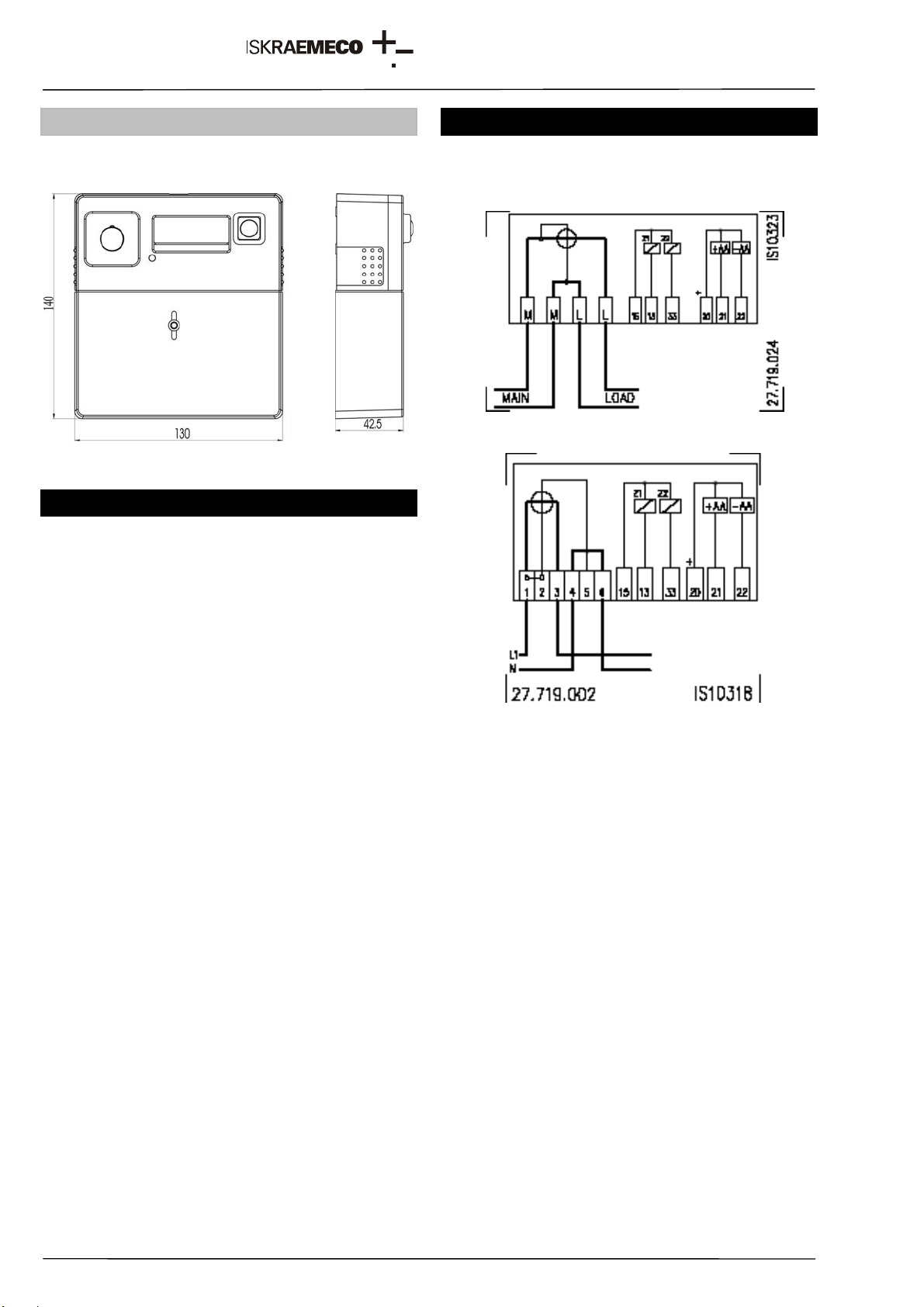
6. Inputs and outputs
6.1. Inputs
The meter is equipped with one (two-rate meters) or
two (3- and 4-rate meters) tariff inputs that are used
for external tariff changeover with a phase voltage.
6.2. Outputs
The meter is equipped with one or two impulse
outputs. Two impulse outputs are used in case of bi-
directional energy flow (an output for each energy
flow direction).
Outputs can be an S0 (IEC 62053-31 type A, DIN
43864) or opto-MOS relay type.
7. Handling with the meter
Two sets of tools are available:
• For service programming and readout:
MeterView (Iskraemeco software)
an optical probe
a PC: a desk-top, a laptop
The tool is intended for the operators who service or
reprogramme the meters in the laboratory or in a
field.
• For billing readout and programming:
MeterRead (Iskraemeco software) for all types of
Palm-top PCs operating in the Windows CE
environment
an optical probe
The tool is intended for meter readers in the field.
CODE /
LCD DESCRIPTION
Stand.
0 Total positive active energy (A+)
0* Total absolute active energy |A|
1 Positive active energy in first tariff (T1)
1* Absolute active energy in first tariff |T1|
2 Positive active energy in second tariff (T2)
2* Absolute active energy in second tariff |T2|
3 Positive active energy in third tariff (T3)
3* Absolute active energy in third tariff |T3|
4 Positive active energy in fourth tariff (T4)
4* Absolute active energy in fourth tariff |T4|
5 Total negative active energy (A-)
6 Negative active energy in first tariff (T1)
7 Negative active energy in second tariff (T2)
8 Negative active energy in third tariff (T3)
9 Negative active energy in fourth tariff (T4)
t Time
d Date YY-MM-DD
F Fatal error