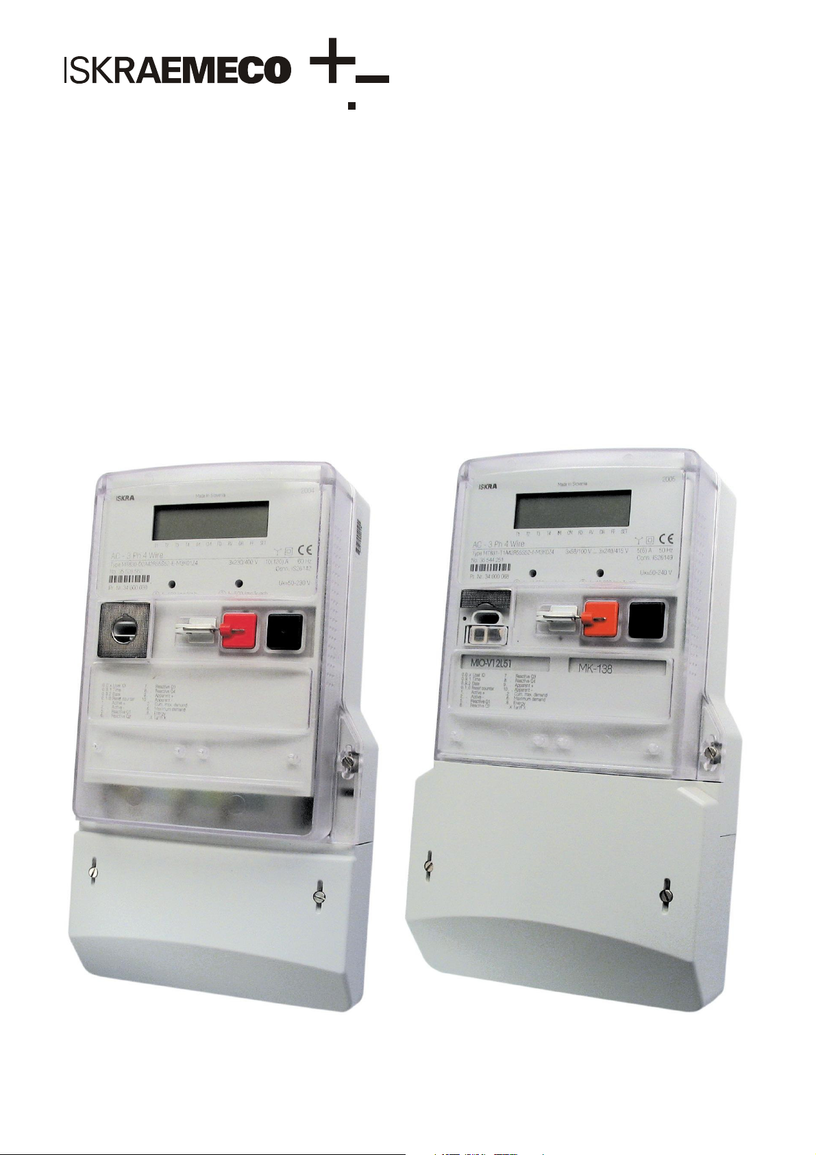
manuals.online logo
Brands
  1. Home
  2. •
  3. Brands
  4. •
  5. ISKRAEMECO
  6. •
  7. Measuring Instrument
  8. •
  9. ISKRAEMECO MT830 User manual

ISKRAEMECO MT830 User manual

This manual suits for next models

1

Other ISKRAEMECO Measuring Instrument manuals

ISKRAEMECO MT880 Manual

ISKRAEMECO

ISKRAEMECO MT880 Manual

ISKRAEMECO MT382 User manual

ISKRAEMECO

ISKRAEMECO MT382 User manual

ISKRAEMECO ME162 Parts list manual

ISKRAEMECO

ISKRAEMECO ME162 Parts list manual

ISKRAEMECO ME371 Parts list manual

ISKRAEMECO

ISKRAEMECO ME371 Parts list manual

ISKRAEMECO ME382 User manual

ISKRAEMECO

ISKRAEMECO ME382 User manual

ISKRAEMECO MT174 User manual

ISKRAEMECO

ISKRAEMECO MT174 User manual

Popular Measuring Instrument manuals by other brands

Powerfix Profi 278296 Operation and safety notes

Powerfix Profi

Powerfix Profi 278296 Operation and safety notes

Test Equipment Depot GVT-427B user manual

Test Equipment Depot

Test Equipment Depot GVT-427B user manual

Fieldpiece ACH Operator's manual

Fieldpiece

Fieldpiece ACH Operator's manual

FLYSURFER VIRON3 user manual

FLYSURFER

FLYSURFER VIRON3 user manual

GMW TG uni 1 operating manual

GMW

GMW TG uni 1 operating manual

Downeaster Wind & Weather Medallion Series instruction manual

Downeaster

Downeaster Wind & Weather Medallion Series instruction manual

Hanna Instruments HI96725C instruction manual

Hanna Instruments

Hanna Instruments HI96725C instruction manual

Nokeval KMR260 quick guide

Nokeval

Nokeval KMR260 quick guide

HOKUYO AUTOMATIC UBG-05LN instruction manual

HOKUYO AUTOMATIC

HOKUYO AUTOMATIC UBG-05LN instruction manual

Fluke 96000 Series Operator's manual

Fluke

Fluke 96000 Series Operator's manual

Test Products International SP565 user manual

Test Products International

Test Products International SP565 user manual

General Sleep Zmachine Insight+ DT-200 Service manual

General Sleep

General Sleep Zmachine Insight+ DT-200 Service manual

Sensa Core Lacto Spark user manual

Sensa Core

Sensa Core Lacto Spark user manual

VOLTCRAFT UTS-1980 operating instructions

VOLTCRAFT

VOLTCRAFT UTS-1980 operating instructions

EBCHQ 94915 Operation manual

EBCHQ

EBCHQ 94915 Operation manual

Balluff BIP LD2-T017-01-EP-S4 Series user guide

Balluff

Balluff BIP LD2-T017-01-EP-S4 Series user guide

Pulsar IMP Lite Series instruction manual

Pulsar

Pulsar IMP Lite Series instruction manual

ETCR 6800 user manual

ETCR

ETCR 6800 user manual

manuals.online logo
manuals.online logoBrands
  • About & Mission
  • Contact us
  • Privacy Policy
  • Terms and Conditions

Copyright 2025 Manuals.Online. All Rights Reserved.

Energy Measurement and Management
MT830/MT831
Industrial multi-function meter
Installation manual
Version 1.3, 15.05.2008
Page 2
MT830/MT831
Installation manual
Contents
1. Meter parts ..........................................................................................................................................................................4
Meter terminals....................................................................................................................................................................5
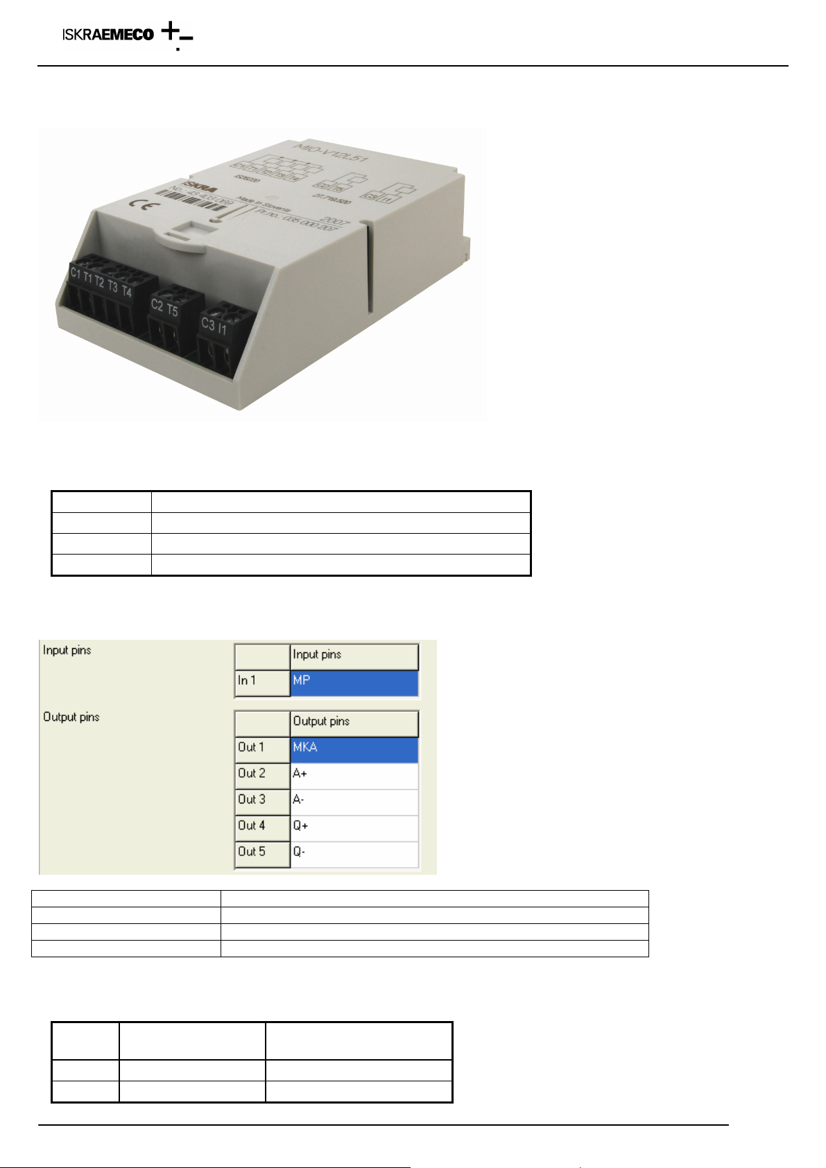
Input – Output modules .......................................................................................................................................................7
Communication modules...................................................................................................................................................10
Front plate .........................................................................................................................................................................12
Power supply.....................................................................................................................................................................14
2. Installation .........................................................................................................................................................................16
3. Checking the meter...........................................................................................................................................................20
Voltages.............................................................................................................................................................................20
Load...................................................................................................................................................................................21
4. Meter handling ..................................................................................................................................................................21
5. Display ..............................................................................................................................................................................22
2.4.2 Power flow direction and quadrant indicator ........................................................................................................24
2.4.3 Phase voltages indicator ......................................................................................................................................24
Display test ........................................................................................................................................................................25
6. Display handling................................................................................................................................................................25
Menus on the display ........................................................................................................................................................31
6.1.1 Auto menu and Std dAtA display..........................................................................................................................31
6.1.2 GRID menu...........................................................................................................................................................34
6.1.3 DIAG menu (for GSM modem only) .....................................................................................................................36
7. Setup meter time setup by pushbuttons ..........................................................................................................................36
8. GSM/GPRS communication module MK – f38a –3 .........................................................................................................37
9. Meter reading with MeterView ..........................................................................................................................................42
Reading the meter via optical probe in the meter .............................................................................................................42
Reading the meter via RS-232 or RS-485 or current loop communication interface in the meter....................................43
Reading the meter via GSM or PSTN or ISDN modem in the meter – selection “Standard modem” ..............................44
Reading the meter via GSM or PSTN or ISDN modem in the meter – selection “Custom modem”.................................46
Reading the meter via Ethernet – transparent type ..........................................................................................................47
Reading the meter via Ethernet – consereth type.............................................................................................................48
9.6.1Setup the IP number in the Ethernet module – consereth type ..........................................................................48
Reading the meter via GPRS modem in the meter...........................................................................................................51
10. GPRS network connection setting in Windows XP system ...........................................................................................52
11. Meter data reading with MeterViev .................................................................................................................................56
Data read out reading........................................................................................................................................................56
Load profile reading...........................................................................................................................................................57
Log book reading...............................................................................................................................................................62
Setting time and date with MeterView...............................................................................................................................62
11.3.1 With command W5 ............................................................................................................................................62
11.3.2 With command W1 ............................................................................................................................................63
Programming the meter MT83x.........................................................................................................................................64
11.5.1 Entering the Password .......................................................................................................................................64
11.5.2 Reading the Parameters.....................................................................................................................................66
11.5.3 Writting the Parameters......................................................................................................................................68
12. MT83x meter parameters................................................................................................................................................69
12.1 Open the existing parameters from the Meter View..................................................................................................69
12.2.2 Group

Device information ..............................................................................................................................71
12.2.3 Group

Display ................................................................................................................................................73
13. Adding support for new meters.......................................................................................................................................81
14. Installation of SONDA 5 USB driver ...............................................................................................................................84
15. Technical data.................................................................................................................................................................90
DOCUMENTATION
Technical and programming details on the MT830/MT831 meter can be found in:
•MT830-MT831_ENG V1,1.pdf: Technical description,
•MeterView 4: Users manual.
Page 3
MT830/MT831
Installation manual
WARNING!
The meter installation must be performed by authorized persons, who are familiar with security against electric
current stroke. Feed-through terminals and auxiliary terminals are under voltage that can be lethal!
Page 4
MT830/MT831
Installation manual
1. Meter parts
Fig. 1: Meter parts
1. LCD display
2. Meter technical data
3. IR optical interface
4. Input/output module mark
5. Legend of displaying registers on LCD
6. Meter cover sealing screw
7. Terminal cover
8. Terminal cover sealing screw
9. Communication module mark
10. RESET key blocking element
11. RESET key
12. DISPLAY key
13. Impulse diode – active and reactive energy
14. Meter cover
1
2
3
4
6
5
6
7
8
8
9
10 11
12
13
Page 5
MT830/MT831
Installation manual
Meter and fixing dimensions comply with the DIN 43857 standard.
Fig. 2: Dimensions (MT831 meter) Fig. 3: Dimensions (MT830 meter)
A compact plastic casing is made of high quality self-extinguishable materials and is resistant to water and dust (IP53).
Meter terminals
MT830 meter
Voltage terminals Auxiliary terminals
Fig.4: Terminal block – direct connected meter MT830
Sensor for terminal cover opening
Voltage link
Additional voltage terminal
Page 6
MT830/MT831
Installation manual
Closed – opened voltage link:
Fig. 5: Voltage link – direct connected meter
There are 6 auxiliary terminals on the meter basic board. They could be defined as inputs (max. 2), outputs (max. 4),
communication (CS or RS-232 or RS-485) and external power supply.
To access terminal block remove terminal cover (8, Fig. 1: Meter parts), fixed with two screws (9). Seals from screws
must be removed.
Voltage and current terminals Auxiliary terminals
Fig. 6: Terminal block – indirect connected meter MT830
MT831 meter (with input/output and communication module)
There are 6 auxiliary terminals on the meter basic board. They could be defind as inputs (max. 2) and external power
supply. Additional inputs and outputs are located in the module.
Voltage link is opened
Voltage link is closed
Sensor for terminal cover opening
Additional voltage terminal
Page 7
MT830/MT831
Installation manual
Auxiliary terminals
Voltage and current terminals
Fig. 7: Terminal block – indirect connected meter MT831
Auxiliary terminals
Voltage and current terminals
Fig. 8: Terminal block – direct connected meter MT831
Input – Output modules
Regarding the module programming, two versions exists:
•“Factory preprogrammed” modules: terminal function is burned in the module memory, meter automatically
acccept the module setting, terminals are denotated according to the VDEW denotation, modules could be
reprogrammed only in the factory or with special factory tool – Module Programmator
•“Empty” modules: modules are programmed as empty, terminal function is defined by meter parameters – meter
defines the terminal function, terminals are denotated as T1, .. Tn for outputs and I1, In for inputs
When moudule is inserted into the meter, cursor IM must be ON. If it blinks, module is not programmed properly or it is
not programmed at all. Module must be sent back to the factory.
Sensor for terminal cover opening
Communication module
Input-output module
Input-output module
Sensor for terminal cover opening
Additional voltage terminal
Page 8
MT830/MT831
Installation manual
Connection diagram for modules is printed on the module itself and on the label, on the bottom side of the terminal cover.
Definition of input terminals – factory programmed input – output module (function is define in the module)
Fig. 9: Factory programmed input -output module
Terminal
Terminal
designation Additional explanation
15 COM Common terminal for functional inputs
13, 33 TE1/2, TE3/4 Energy tariff input T1 – T4
14, 34 ME1/2, ME3/4 Demand tariff input M1 – M4
16 MPE External time/measurement period synchronization input
17 MZE External input for disabling of demand measurement
18 MREa Input a for external billing reset
19 MREb Input b for external billing reset
35 COM Common terminal
36 MKA Alarm output
37 MPA Measurement period output
38 ERA+A Energy flow direction +A
39 ERA+R Energy flow direction +R
40 COM Common terminal
41 +AA Pulse output +A
42 -AA Pulse output -A
43 +RA Pulse output +R
44 -RA Pulse output -R
45 RA1 Pulse output RA1
46 RA2 Pulse output RA2
47 RA3 Pulse output RA3
48 RA4 Pulse output RA4
65 COM Common terminal
61, 63 TA1/2, TA3/4 Demand tariff outputs T1 – T4
62, 64 MA1/2, MA3/4 Demand tariff outputs M1 – M4
67 MZA Output for disabled max. demand measurement
68 MRAa Output for external billing reset a
69 MRAb Output for external billing reset b
Page 9
MT830/MT831
Installation manual
Definition of input terminals – non-programmed input – output module (function is defined by the parameters in
the meter)
Fig. 10: Default »non-programmed« input -output module
Terminal Additional explanation
C1, C2, C3 Common terminal for functional inputs or outputs
I1, I1, I3, I4 Input terminals
T1, …, T8 Output terminals
Function of input (output) terminal is written on the meter connection diagram (sticked on the bottom terminal cover side).
It could be also read out with the MeterView program:
Module designation
MIO-V12L51 1 x input, 4 x OPTOMOS outputs, 1 x OPTOMOS output
MIO-V42L81 4 x input, 4 x OPTOMOS outputs, 4 x OPTOMOS output
MIO-V12L41B11 1 x input, 4 x OPTOMOS outputs, 1 x bistable 5A relay output
Definition of external power supply
Terminal
Terminal
designation Additional explanation
30 50 – 240 V AC/DC External power supply
31 50 – 240 V AC/DC External power supply
Page 10
MT830/MT831
Installation manual
Communication modules
Regarding the module programming, two versions exists:
•“Factory preprogrammed” modules: communication parameters are burned in the module memory, meter
automatically acccept the module setting, modules could be reprogrammed only in the factory or with special
factory tool – Module Programmator
•“Empty” modules: modules are programmed as empty, communication parameters could be changed by meter
parameters
When moudule is inserted into the meter, cursor CM must be ON. If it blinks, module is not programmed properly or it is
not programmed at all. Module must be sent back to the factory.
Each module has two independend communication interfaces:
•primary
•secondary
“Passive” communication modules (modules without modem):
MK-2-3 

RS-232 & RS-485
MK-3-3 

RS-485 & RS-485
MK-1-3 

CS & RS-485
Module designation Primary interface Secondary interface
MK-2-3 RS-232 RS-485
MK-3-3 RS-485 RS-485
MK-1-3 Curent loop RS-485
Primary and secondary communication interfaces are defined by the hardware in the module. Denotation expresess,
which interface is primary and which is secondary.
Communication module MK-2-3 (RS-232 & RS-485) :
Primary interface (RS-232) Secondary interface (RS-485)
Meter enables simultaneously reading via the both interfaces at the same time. Secondary communication interface is
shared with IR optical interface – when communication runs via optical probe, communication via interface in the module
is not possible.