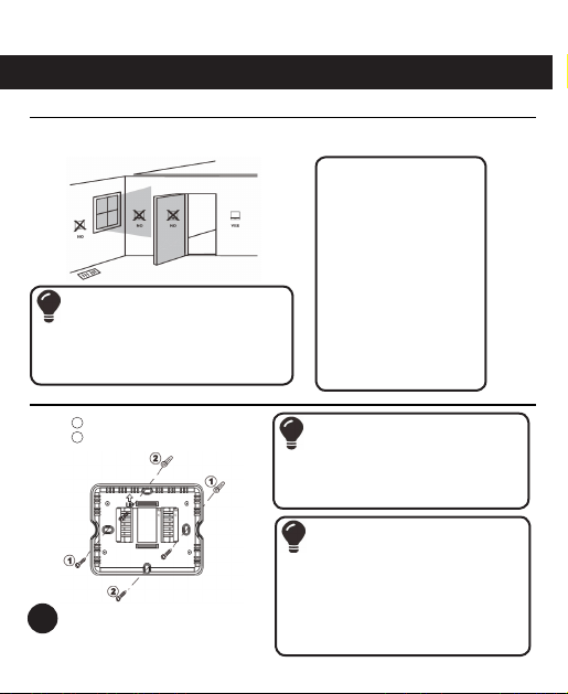
Islandaire 6041210 User manual

7-DAY PROGRAMMABLE
WIRELESS THERMOSTAT
6041210
Installaon and Operaon Manual
6140435 Rev. 10/13/20


Descripon
Gas or Oil Heat Yes
Electric Furnace Yes
Heat Pump (No Aux. or Emergency Heat) Yes
Heat Pump (With Electric Aux.) Yes
Heat Pump (With Gas Aux.) No
Mul-Stage Systems No
Heat Only Systems - Floor or Wall Furnace Yes
Cool Only Systems Yes
High and Low Fan Speed Yes
Millivolt No
Emergency Heat No
Convenonal Single-Stage Furnace Yes
Geothermal Yes
Table of Contents page
Thermostat Applicaon Guide
Baery Power
Hardwire (Common Wire)
Hardwire (Common Wire) with
Baery Backup
A trained, experienced technician
must install this product.
Carefully read these instrucons. You
could damage this product or cause
a hazardous condion if you fail to
follow these instrucons.
Power Type
Installaon Tips 2
Thermostat Quick Reference 4
Wiring 5
Wiring Diagrams 7
Technician Setup 9
RF Pairing 13
Programming 14
Features 18
Specicaons 19
1
Installaon and Operaon Manual

Wall Locaons
The thermostat should be installed approximately 4 to 5 feet above the oor. Select an area
with average temperature and good air circulaon.
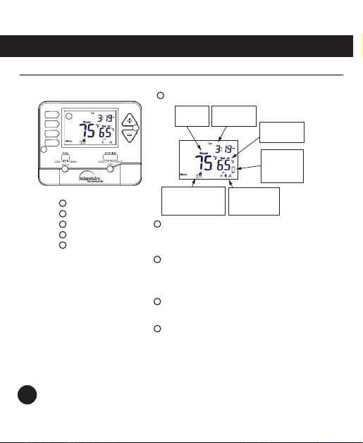
Subbase Installaon
Horizontal Mount
Vertical Mount
1
2
For vercal mount, put one screw on the top
and one screw on the boom.
For horizontal mount, put one screw on the le
and one screw on the right.
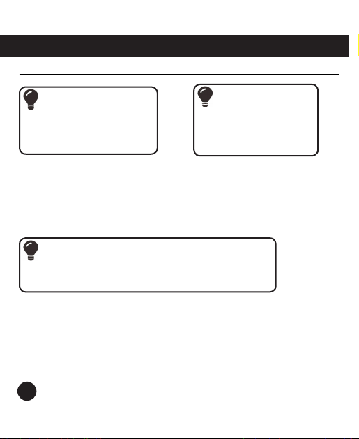
Installaon Tip
Pick an installaon locaon that is easy for
the user to access. The temperature of the
locaon should be representave of the
room.
Do not install
thermostat in locaons:
• Close to hot or cold
air ducts
• That are in direct sunlight
• On an outside wall
• In areas that do not
require condioning
• Where there are dead
spots or dras
(i.e., in corners or behind
doors)
• Where there might be
concealed chimneys
or pipes
Installaon Tip
Electrical Hazard
Failure to disconnect the power before
beginning to install this product can cause
electrical shock or equipment damage.
Mercury Noce
All of our products are mercury free.
However, if the product you are replacing
contains mercury, dispose of it properly.
Your local waste management authority can
give you instrucons on recycling and proper
disposal.
2
Installaon Tips

Installaon Manual
Mount Thermostat
Align the 4 tabs on the subbase with corresponding slots on the back of the thermostat,
then push gently unl the thermostat snaps in place.
Baery Installaon
1.5V AAA 1.5V AAA
Baery installaon is oponal if thermostat is
hardwired (RH and C terminal connected to 24V
power).
Important:
High quality alkaline baeries are recommended.
Rechargeable baeries or low quality baeries
do not guarantee a 1-year life span.
Insert 2 AAA
Alkaline baeries
(included). High
quality alkaline
baeries are
recommended.
RH
C
3
Installaon Tips

Geng to know your thermostat
1
5
4
32
LCD
Fan Switch
System Switch
Setpoint Buons
Menu Buon
Indicates the
current room
temperature
Displays current
day of week
and me
System Operaon
indicators: On will
display when Cool or
Heat mode is selected
Low Baery
indicator:
Replace baeries
when indicator
is shown
1
2
3
4
Press the + or - buttons to select the desired room
temperature.
LCD
1
AUTO will turn the fan on only when the heating
or cooling system is on. Select LOW or HIGH for
the fan to run continuously at the selected speed.
Fan Switch
2
3
4
Selects the operation mode on your HVAC system.
Selecting HEAT turns on the heat mode. Selecting
COOL turns on the cool mode. Selecting OFF turns
both heating and cooling o.
System Switch
Setpoint Buons
5
Time Period indicator:
Indicates current
program me period
(Wake, Leave, Return, Sleep)
Press the Menu Button to create or modify the
thermostat program schedule.
5Menu Buon
Displays the user
selectable setpoint
temperature
4
Thermostat Quick Reference

Wiring
This thermostat is shipped from the factory to operate a convenonal heang and cooling
system. This thermostat will also operate a heat pump system. See the “heat pump”
conguraon step on page 10 of this manual to congure the thermostat for heat pump
applicaons.
If you are replacing a thermostat, make note of the terminal connecons on the thermostat
being replaced. In some cases the wiring connecons will not be color coded. For example,
the red wire may not be connected to the R terminal.
Terminal 1 Heat 1 Cool
Convenonal System
1 Heat 1 Cool
Heat Pump System
2 Heat 1 Cool
Heat Pump System
R Transformer power Transformer power Transformer power
CTransformer common Transformer common Transformer common
B/O Energized in heang /
Energized in cooling
Energized in heang /
Energized in cooling
Energized in heang / Ener-
gized in cooling
GL Fan Relay, Low Fan Relay, Low Fan Relay, Low
GH Fan Relay, High Fan Relay, High Fan Relay, High
W Convenonal heat N/A Emergency heat
YEnergized in cooling Energized in heat & cool Energized in heat & cool
5
Wiring

Wiring Tips
Power Connecons
The thermostat can be either baery
powered, or hard-wired to power by
connecng supply voltage wire (red) and
common wire to the RH and C terminals,
respecvely, on the base.
Installaon Tip
Electrical Hazard
Failure to disconnect the power
before beginning to install this
product can cause electrical shock or
equipment damage.
Wire Specicaons
Use shielded or non-shielded
18-22 gauge thermostat wire.
Warning:
All components of the control
system and the thermostat
installaon must conform to Class
ll circuits per the NEC Code.
Note:
When connecng the 6041210 thermostat to a PTAC, refer to the PTAC
unit’s instrucons to enable remote thermostat operaon.
6
Wiring

R
Y
W
C
GL
GH
C
R
L1
L2
COMPRESSOR
RELAY
HEAT RELAY
FAN LOW RELAY
FAN HIGH RELAY
1
C
R
L1
L2
COMPRESSOR
RELAY
HEAT RELAY
FAN RELAY
1
2
R
Y
W
C
GL
GH
B
3
3
B
Typical 1H/1C Convenonal System: 2 Speed Fan
1
2
3
Power supply
Splice together GL and GH wires.
Cap off B.
Typical 1H/1C Convenonal System: 1 Speed Fan
7
Wiring Diagrams

C
R
L1
L2
COMPRESSOR
RELAY
CHANGEOVER VALVE
FAN LOW RELAY
FAN HIGH RELAY
1
3
C
R
L1
L2
COMPRESSOR
RELAY
CHANGEOVER VALVE
FAN LOW RELAY
FAN HIGH RELAY
1
B
3
EMERGENCY
HEAT RELAY
R
Y
W
C
GL
GH
B
R
Y
W
C
GL
GH
Typical 1H/1C Heat Pump System: 2 Speed Fan
Typical 2H/1C Heat Pump System: 2 Speed Fan
1
2
3
Power supply
Cap off W
Thermostat must be set to B on all Heat Pump Systems
2
Note:
Most PTAC systems support two speed fan operaon. In a single speed
fan PTAC system or convenonal single speed fan system, the GL and GH
wires on the receiver unit should both be ed to the Fan Wire (green).
8
Wiring Diagrams

Technician Setup Menu
This thermostat has a technician setup menu for easy installer conguraon. To set up the
thermostat for your parcular applicaon:
1. Press the Menu buon.
2. Press and hold the Tech Set buon for 3 seconds. This three second delay is designed so
that homeowners do not accidentally access the installer sengs.
3. Congure the installer opons as desired using the table below. Use the “+” and “-” keys
to change sengs and Prev and Next keys to move from one step to another. Note: Press
the Done key to exit Tech Setup Menu.
Tech Setup Steps LCD Will Show Adjustment Opons Default
Filter Change
Reminder
This feature will ash
a reminder aer the
elapsed run me to
remind the user to
change the lter. A
seng of “OFF” will
disable this funcon.
You can adjust the
lter change reminder
from “OFF” to 2000
hours of fan runme
in 50 hour increments.
Pair Transmier and receiver
pair code
Press and hold “+” for
5 seconds unl “LE”
is ashed, then release
Room
Temperature
Calibraon
This feature allows the
installer to change the
calibraon of the room
temperature display.
For example, if the
thermostat reads 70°
and you would like it to
read 72°, then select 2.
°F
You can adjust the
room temperature
display to read up to
3˚ above or below
the factory calibrated
reading.
°F
9
Technician Setup

Tech Setup Steps LCD Will Show Adjustment Opons Default
Minimum
Compressor
On Time
This feature allows the
installer to select the
minimum run me
for the compressor.
For example, a seng
of 4 will force the
compressor to run for
at least 4 minutes every
me the compressor
turns on, regardless of
the room temperature.
MinCom On
You can set the
minimum compressor
run me to “OFF”, “3”,
“4”, or “5” minutes. If
3, 4, or 5 is selected,
the compressor will
run for at least the
selected me before
turning o.
MinCom On
Compressor
Short Cycle
Delay
The compressor short
cycle delay protects the
compressor from short
cycling. This feature
will not allow the
compressor to be turned
on for 5 minutes aer it
was last turned o.
ComDelay
Selecng ON will not
allow the compressor
to be turned on for 5
minutes aer the last
me the compressor
was switched o.
Select OFF to remove
this delay.
ComDelay
Change
Over Value
Selecon
(Heat Pump
Units)*
Select 0 for a change-
over valve that energizes
in cooling. Select b for
a changeover valve that
energizes in heang.
0 for cooling
changeover valve.
b for heang
changeover valve.
Heat Pump When turned on the
thermostat will operate
a heat pump. Y will be
the rst stage of heat
& cool, W will be the
second stage of heat.
OFF congures the
thermostat for non
heat pump systems.
ON congures the
thermostat for heat
pump systems.
* All Islandaire units should always be set to b
10
Technician Setup Menu

Tech Setup Steps LCD Will Show Adjustment Opons Default
Cooling
Swing
The swing seng,
oen called “cycle rate”,
“dierenal” or “anci-
paon”, is adjustable. A
smaller swing seng
will cause more frequent
cycles and a larger swing
seng will cause fewer
cycles.
CoolSwing
The cooling swing
seng is adjustable
from 0.2° to 2°. For ex-
ample: A swing seng
of 0.5° will turn the
cooling on at approxi-
mately 0.5° above the
setpoint and turn the
cooling o at approxi-
mately 0.5° below the
setpoint.
CoolSwing
Heang
Swing*
The swing seng,
oen called “cycle rate”,
“dierenal” or “anci-
paon”, is adjustable. A
smaller swing seng
will cause more frequent
cycles and a larger swing
seng will cause fewer
cycles.
Heat
Swing
The heang swing
seng is adjustable
from 0.2° to 2°. For
example: A swing
seng of 0.4° will
turn the heang on at
approximately 0.4° be-
low the setpoint and
turn the heang o
at approximately 0.4°
above the setpoint.
Heat
Swing
Heang
Temperature
Setpoint
Limit
This feature allows you
to set a maximum heat
setpoint value. The
setpoint temperature
cannot be raised above
this value.
Use the “+” or “-” key
to set the maximum
temperature setpoint:
44.0˚ - 90.0˚ F
7.0˚ - 32.0˚ C
* The second stage of heat will turn on at 2x the swing seng. The second stage will turn o when
1x the swing is reached. For example, if the swing seng is 0.8° for heang and the thermostat is
set at 70 °F, the rst stage will turn on at approximately 69.2 °F. The second stage will turn on at
68.4 °F and the rst will turn o at 70.8 °F.
11
Technician Setup Menu

Tech Setup Steps LCD Will Show Adjustment Opons Default
Cooling
Temperature
Setpoint
Limit
This feature allows you
to set a maximum cool
setpoint value. The
setpoint temperature
cannot be raised above
this value.
Use the “+” or “-” key
to set the maximum
temperature setpoint:
44.0˚ - 90.0˚ F
7.0˚ - 32.0˚ C
F or C Select F for Fahrenheit
temperature read out.
Select C for Celsius tem-
perature read out.
Use the “+” or “-”
key to select F for
Fahrenheit or C for
Celsius.
12 or 24
Hour Clock
You can select either a
12 or 24 hour clock.
Use the “+” or “-” key
to select 12 or 24 hour
clock.
Electric/Gas This seng allows the
thermostat to operate
the fan during a call for
heat. For systems that
control the fan during
a call for heat, put
the switch in the GAS
posion.
Most PTAC systems
will require ELEC Fan
Operaon Setup. The
thermostat operaon
switch should be put
in the ELEC posion.
Program
Opons
You can congure this
thermostat to have a 7
day program, a 5+1+1
program, or as non-
programmable.
Use the “+” or “-” key
to select 7d for 7 days,
5d for 5+1+1, or 0d for
non-programmable.
12
Technician Setup Menu

RF Pairing
1. Receiver Unit: Insert a slender object into the hole and keep it depressed for
approximately 5 seconds unl the red LED starts ashing.
2. Transmier Unit: Turn the SYSTEM switch to OFF. Press the Menu buon. Press and hold
the Tech Set buon for 5 seconds to access the Installer Sengs screens. Press the Next
Step buon unl “LE” is displayed on the LCD, then press and hold second key from the
top for 5 seconds unl “LE” is ashed, then release. When the red LED on the receiver
unit stops ashing, this indicates the code transmission was successful.
Note: For a Master/Slave setup, a Receiver Unit is required on each PTAC. Each
Receiver Unit (Master and Slave) must be acvated as described in step 1 above,
then each receiver is paired with the Transmier Unit as described in step 2.
Set Time
Follow the steps below to set the day of the week and current me:
1. Press the Menu buon.
2. Press Set Time buon.
3. The day of the week will be ashing. Use the “+” or “-” key to select the current day of
the week.
4. Press the Next Step buon.
5. The current hour will be ashing. Use the “+” or “-” key to select the current hour. When
using the 12 hour me seng, ensure “AM” or “PM” is appropriately selected.
6. Press the Next Step buon.
7. The current minutes will be ashing. Use the “+” or “-” key to select the current minutes.
8. Press the Done buon.
13
RF Pairing

Programming
The 6041210 Thermostat is shipped with an energy saving default program. The thermostat
can be re-programmed as described in the paragraph entled “Set Program Schedule”.
There are two program schedule opons:
• 7 days - Each day of the week programmed individually
• 5+1+1 - All weekdays have the same program, separate programs for Saturday and Sunday
Alternavely, the thermostat can be set to manual temperature control (non-
programmable).
For the 7 day and 5+1+1 programming opons, there are four me periods:
• Wake
• Leave
• Return
• Sleep
14
Programming

Default Programming
Factory Default Program
Day of
Week
Time Period Time Setpoint
Temperature
(Heat)
Setpoint
Temperature
(Cool)
Weekday
Wake 6 AM 70°F (21°C) 75°F (24°C)
Leave 8 AM 62°F (17°C) 83°F (28°C)
Return 6 PM 70°F (21°C) 75°F (24°C)
Sleep 10 PM 62°F (17°C) 78°F (26°C)
Saturday
Wake 6 AM 70°F (21°C) 75°F (24°C)
Leave 8 AM 62°F (17°C) 83°F (28°C)
Return 6 PM 70°F (21°C) 75°F (24°C)
Sleep 10 PM 62°F (17°C) 78°F (26°C)
Sunday
Wake 6 AM 70°F (21°C) 75°F (24°C)
Leave 8 AM 62°F (17°C) 83°F (28°C)
Return 6 PM 70°F (21°C) 75°F (24°C)
Sleep 10 PM 62°F (17°C) 78°F (26°C)
15
Programming

Set Program Schedule (7 Day Schedule)
To customize your 7 day program schedule, proceed as follows:
1. Set the System Switch to either Heat or Cool. Note: You have to program heat and cool
separately.
2. Press the Menu buon.
3. Press Set Schedule buon.
4. Monday (Mon) is displayed and the me seng will be ashing; the “Wake” me period
icon is displayed at the boom of the screen. Use the “+” or “-” key to set the desired
Wake me. When using the 12 hour me seng, ensure “AM” or “PM” is appropriately
selected.
5. Press the Next Step buon.
6. The “Set At” temperature will be ashing. Use the “+” or “-” key to select the desired
temperature seng for the Wake me period.
7. Press the Next Step buon.
8. Repeat steps 4 through 7 for that day’s Leave, Return and Sleep me periods.
9. Press the Next Step buon.
10. Repeat steps 4 through 7 for the remaining days of the week.
11. Press the Done buon.
Note: Repeat this process for heat and cool separately.
16
Programming

Set Program Schedule (5+1+1 Schedule)
To customize your 5+1+1 day program schedule (weekday, Saturday, Sunday), proceed as
follows:
1. Set the System Switch to either Heat or Cool.
Note: You have to program heat and cool separately.
2. Press the Menu buon.
3. Press Set Schedule buon.
4. “Mon Tue Wed Thu Fri” is displayed and the me seng will be ashing; the “Wake”
me period icon is displayed at the boom of the screen. Use the “+” or “-” key to set
the desired Wake me. When using the 12 hour me seng, ensure “AM” or “PM” is
appropriately selected.
5. Press the Next Step buon.
6. The “Set At” temperature will be ashing. Use the “+” or “-” key to select the desired
temperature seng for the Wake me period.
7. Press the Next Step buon.
8. Repeat steps 4 through 7 for that day’s Leave, Return and Sleep me periods.
9. Press the Next Step buon.
10. Saturday (Sat) is displayed and the me seng will be ashing; the “Wake” me period
icon is displayed at the boom of the screen. Repeat steps 4 through 9 for Saturday’s
Leave, Return and Sleep me periods.
11. Press the Next Step buon.
12. Sunday (Sun) is displayed and the me seng will be ashing; the “Wake” me period
icon is displayed at the boom of the screen. Repeat steps 4 through 9 for Sunday’s
Leave, Return and Sleep me periods.
13. Press the Next Step buon.
14. Press the Done buon.
Note: Repeat this process for heat and cool separately.
17
Programming

Temporary and Permanent Hold
Temporary Hold: The thermostat will display “Hold” and “Run Sched” on the le side of the
screen when you press the “+” or “-” key. If you do nothing, the temperature will remain at
this setpoint temporarily for four hours. Aer this me, the thermostat will revert back to
programmed temperature control.
At any me during temporary temperature hold, press the Run Sched buon to exit
temporary temperature hold.
Permanent Hold: The thermostat will display “Hold” and “Run Sched” on the le side of
the screen when you press the “+” or “-” key. If you press the Hold key at the le side of
your screen you will see “Hold” appear above the setpoint temperature in the display. The
thermostat will now permanently stay at this setpoint and can be adjusted using the “+” and
“-” keys.
At any me during permanent temperature hold, press the Run Sched buon to exit
permanent temperature hold.
Filter Change Reminder
If the lter change reminder has been set, you will see a reminder (“Filter”) appear in the
display when your air lter needs to be changed. Note: Once a reminder has been set in the
technician setup menu, the elapsed me can be checked by navigang to the Filter Change
Reminder screen, then press the key below the Next Step key.
The reminder will appear aer the system has run long enough to exceed the number of
hours set in the Tech Setup Menu. To reset the lter change reminder, change your lter
and then hold down the second key from the top for ve seconds.
18
Features
Table of contents
Other Islandaire Thermostat manuals
Popular Thermostat manuals by other brands

Venstar
Venstar T1010 installation instructions

Pro1 Technologies
Pro1 Technologies T855SH installation manual

Hoffman Controls
Hoffman Controls 207-W Series Installation & operating instructions

National Semiconductor
National Semiconductor LM26 Series manual

INTEREL
INTEREL EOS installation manual

Braeburn
Braeburn Premier 5100 user manual