Wiring Tips
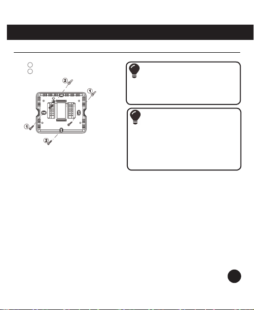
Power Connecons
The thermostat can be either baery
powered, or hard-wired to power by
connecng supply voltage wire (red) and
common wire to the RH and C terminals,
respecvely, on the base.
Note: Installing baeries will enable the
thermostat to remember the program
that you have set even if there has been a
power outage.
Installaon Tip
Electrical Hazard
Failure to disconnect the power
before beginning to install this
product can cause electrical shock or
equipment damage.
Note:
When connecng the 6041228
thermostat to a PTAC, refer to the
PTAC unit’s instrucons to enable
remote thermostat operaon.
Wire Specicaons
Use shielded or non-shielded
18-22 gauge thermostat wire.
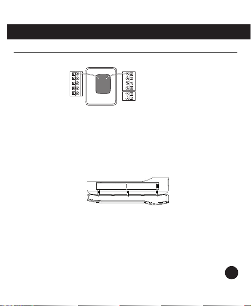
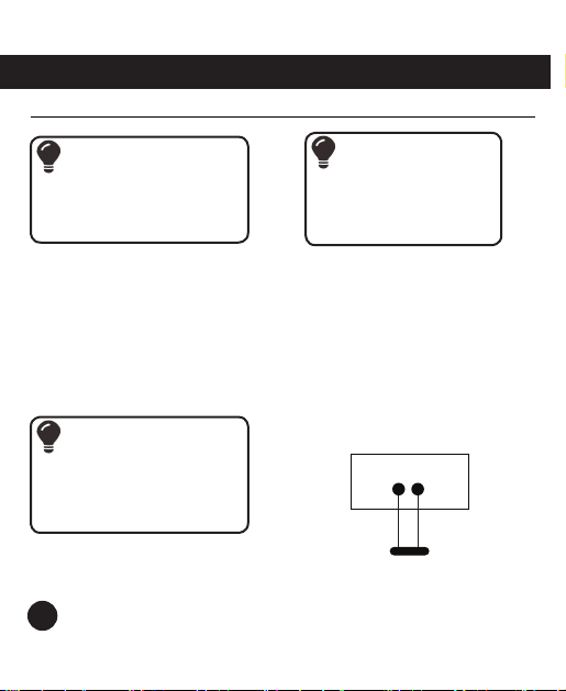
Remote Temperature Sensor
Connecons
Use the S1 and S2 screw terminals to
connect the oponal indoor remote
temperature sensor (Islandaire part no.
6040912). Indoor remote sensor wires
must be separated from the thermostat
wires.
Warning:
All components of the control
system and the thermostat
installaon must conform to
Class ll circuits per the NEC Code.
THERMOSTAT
REMOTE TEMPERATURE
SENSOR
P/N 6040912
S1 S2
8
Wiring